1
®
Advanced Test Equipment Rentals
www.atecorp.com 800-404-ATEC (2832)
E stablished 1981
AFG 2020
AWG 2020
these
Arbitrary Generators
Signal Sources
AWG 2020
).H{jlll"r\!
Waveform
ARB's 1'.7th our
2400 or
TVS Series
• 256K (262,144
Points) Record
Length
• Built-in PC-
cOlnpJ'ete test
Additional
fle.:ribility with the
A\iliG 2020 built
in controller and
COlllp(ltibJe
PC
• ODS-like VVaveforrn
disk.
File ManaQlement
• Formula
Parameters
Precise
W'\IPrnrnl~
AFG 2020
• 100 MHz Sinewave
Generation
• 50 MHz
Wave
2 MHz
and Pulse
• AM/FM/PSKIFSK
Modulation
• Built-in
To order, rnnj"f't ,.mllr
local sales office
on the inside back cover)
or call the National
Center at
1-8Clr'r4:'6-2:200. Ext 99.
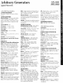
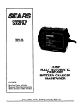
New AWG/AFG 2000 Series
The Tektronix AVVG 2020 and AFG 2020
Generators combine the function of
generator with a controller and a
graphi(;a user interface. A built-in nlnll-r~',nl"
monitor facilitates waveform definition
The AVVG 2020 and
2020 share a common
user interface
and monolitt1ic
While the basic
is similar, each unit
The AWG 2020 is
waveforms
to 256K It
a built-in
inch
disk to
and waveform transfers
An ,',AS-DOS
fiie m"nor,pn,pn!
system allows waveform
amJ
transfer wittlOut an external controller for most
enter
the
USE STANDARD WAVEFORMS OR
CREATE YOUR OWN
You can
any of
new
waveform.
the ,t~:nrhrrl wavesllapes
trarlsfarred to
the GPiB - an
for transfer,
HIE PERFECT COMPANION FOR YOUR
TEKTRONIX SCOPE
The AWG 2020 and AFG 2020 feature direct
comr1llmication with the Tektronix
2400,
and lOS series dlQltlZlIlg o:icilloscOpEIS.
Waveforms acqulrElo
transferred to
AFG 2020 or
edited for desired features. ami
as
sequences All of this can be done without the
for an external controller.
FUllY PROGRAMMABLE VIA GPIB
AWG 2020 and AFG
ideal
to
stirnulus and
wavetorm qeneration
your measurement system.
Arbitrary Generators
Signal Sources
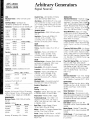
AWG 2020 Characteristics
SYNTHESIZED WAVESHAPES
Sine,
triangle, ramp, pulse,
ARBITRARY WAVEFORMS
Waveform Memory - Memory
256K x
12 bits for waveform data; 256K x bit for
Marker 1 data; 256K x 1 bit tor Marker 2 data.
1Ah,tt>!nrn'1' 64 to 256K in multiples of 8 data
Sequence Memory - 8K.
Scan Counter 1 to 64K (16
Burst Counter - 1 to 64 K (16
RATE CLOCK
Frequency Range - 10 Hz to 250 MHz.
Display - 4
Accuracy - +1 DoC to +40'C 0.01 %. +15 G Cto
t30°C: 0005%
Resolution - 0.1 ''/0 to 001 %
Skew between CH 1 and CH 2 (Opt. 02 only)Within 4 ns,
MAIN OUTPUTS
Amplitude (excluding ADO and Multiply Operation)- Range: 0.05 V to 5 Vp-p into 50 n.
Resolution: 1/4096 (12 bits). DC Accuracy:
0.05 Vto 0.5 V, ±(0.5% of amplitude +5 mV);
0.501 Vto 5 V, ±(1 % of amplitude +25 mV),
Offset - Range: -2.5 V to +2.5 V into 50 n,
00 mA to +100 mAl, Resolution 0.2 mA.
% of offset +0.2
Pulse Response - +15"C to +30°C: Flatness,
within 3% after 20 ns from rise/fail edges;
Ahprr~t;nn~ within 7% +10 mV, +1DoC to
+40"C Rise/Fail Time, <4 ns; Flatness, within
5% after 20 ns from rise/fall edges;
Aberrations, within 9% +10 mV.
Impedance50 n.
Harmonic Distortion
250 MHz clock, 0.5 V
amplitude, 5000 points for sinewave data no
offset, no filter) - Second Harmonics: At least
-40 dBc, Third Harmonics: At least -50 dBc.
OPERATING MODES
Continuous - Output continuous at programmed waveshape, frequency, amplitude,
and offset
Triggered - Output quiescent until triggered by
an external, GPIB, or manual trigger; then generates a sequence only one time.
Gated - Same as triggered mode except period
IS executed
for the duration of tile gated
signal until the sequence started is completed
Burst Output quiescent until tnggered by an
external, GPIB, or manual trigger; then generates "n" sequences or
Waveform Advance - Continuously generates
the waveform in the predefined sequence; the
next trigger advances to the next waveform in
the sequence.
Autostep - Generates the predefined waveform
in the Autostep File; the next trigger advances
the waveform.
ARITHMETIC OPERAnON
AM (Multiply) (Opt. 02 only) Output Within
5% Frequency Response: DC to 30 MHz.
External AM - SensitiVity 2
100% modulation. FrRnllR,nr\l
Respon:se CH 1, DC to 30 MHz;
DC to 4 MHz
Add (Opt. 02 only) - Output Witrlin 5%
Frequency Response DC to 30 MHz.
FILTERS
3 dBcutoff frequency - 1 MHz: Within 20%.
5 MHz: Within 20%. 20 MHz: Within 20%,
50 MHz Within 20%.
Delay - 1 MHz: Typically 390-rn;,-5-MHz:
Typically 78 ns. 20 MHz: Typically 18 ns.
50 MHz Typically 11 ns.
AUXILIARY OUTPUTS
Sync - Amplitude 1 V±0.3 V typical into 50 n.
Impedance 50 ~2
Sync to
Delay
Witllin 15 ns.
Marker 1 - Amplitude 1 V ±O.3 Vtypical into
50 n. Impedance 50 n typical Marker to
Signal Delay: Within 15 ns.
Marker 2 Amplitude: 1 V ±O3 V typical into
50 n. Impedance: 50 n typical Marker to
Signal Deiay Within 15 ns.
Clock - Amplitude 1 V ±O.3 V typical into
50 n, Impedance: 50 Q typical
Digital Data Out (Opt. 03 only)- level ECl
compatible. Output Signals: Data (DO to 011).
Skew Between Data: Within 1 ns. Clock to
Data Delay: Within 3 ns. Connector: 58-pin
mini-D sub.
AUXILIARY INPUTS
Trigger - Threshold level: -5 V to +5 V.
Resolution: 0.1 V Accuracy: ±(5% x level
+ 0,1 V), Pulse Width: 15 ns minimum, Input
Swing: 0.2 V minimum. Maximum Input Volts:
10 Vp-p when 1 Mn se',ected; 5 V RMS when
50 n selected. Impedance 1 Mn witll 30 pF
max. Trigger to Signal Delay Internal Clock,
100 ns maximum; External Clock, 100 ns maximum +1 clock. Trigger Holdoff: 1 sec maximum (except Auto Step Mode),
AFG 2020
AWG2020
AM 2 Vp-p (-1 V to +1 for 100%
modulation, Maximum Input ±5
10 k.n typical impedance.
Clock - Threshold level: 03 V ±0.1 V
Input Swing 0,8 V minimum, Pulse Width 2 ns
minimum. Maximum Input Voltage: ±2 Vp-p
Impedance 50 n
Frequency
Up
to 250 MHz.
PROGRAMMABLE INTERFACE
GPIB - IEEE-488.2-1987 cOrTlpatible
AFG 2020 Characteristics
WAVESHAPES
square, tnangle, ramp, pulse, and
FREQUENCY/PHASE (SYNTHESIZER ON)
Clock - 250 MHz.
Frequency -10 digits.
Sine, 0.5 Hz to
10000 MHz; Other, 0.5 Hz to 2.5 MHz.
Resolution: 0.5 Hz. Accuracy: ±( Reference
Oscillator Accuracy + 0.12 Hz).
Period - Same
as frequency, 2.0 sec to
10,00C:OOOO ns.
Points/Cycle - 5 (jig ItS, 250 MHz divided by
frequency for <100 MHz, up to 1024 or 2048.
Phase - 4 digits. Range:±360°,
Resolution 0.1°.
fREQUENCY/PHASE (SYNTHESIZER Off)
frequency - 3 digits Range: Square, 0.500 Hz
to 50.00 MHz; Other, 0.500 Hz to 31.2 MHz.
Accuracy: ±O.l%.
Period - Same digit as frequency, 2.00 sec to
40.0 ns.
Points/Cycle - 5 digits.
ClocklHate - 512 Hz to 250 MHz.
AMPLITUDE/OFFSET
Amplitude - 4 digits. Resolution: 0.4 Vp-p,
1 mVp-p; 2 Vp-p, 2 mVp-p; 10 Vp-p, 10 mVp-p,
Max. Amplitude 10 Vp-p into 50 n; 20 Vp-p
open circuit.
DC Accuracy Range: 0.4 Vp-p,
.0% of setting +1 mVp-p); 2.0 Vp-p, ±(1 ,0% of setting
+5 mVp-p);10 Vp-p, ±(2.5% of setting
+50 mVp-p),
Offset - 4 digits. Resolution: 0.4 Vp-p, 1 mV;
2 Vp-p, 2 mV; 10 Vp-p, 10 mV, Max Offset:
±5 V into 50 n; ±10 V open circuit. Accuracy:
0.4
t(1.0% of setting +1 mV); 2.0 Vp-p,
of setting +5 mV); 10 Vp-p, ±(2.5% of
setting +50 mV).
Noise Floor - Range: 0.4 Vp-p, -128 dBm/Hz
at 10 MHz; 2.0 Vp-p, -114 dBm/Hz; 10
-100 dBm/Hz,
AFG2020
AWG2020
Arbitrary Generators
Signal Sources
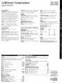
SINE
Maximum Points - 2048; 1024 with synthesizer off,
SSB Phase Noise - Synthesizer Orr
-90 dBc/Hz, Synthesizer Off:--80 dBc/Hz,
Harmonics - Synthesizer On with 100 MHz LPF:
10 Vp-p
_,~Jt~,- 0.4_~..::L-40 dSe
-60 dSe
<100 kHz
1 MHz
-40 dSe
-55 dSe
-35 dSe-55 dSe
10 MHz
100 MHz
-25dSe
-30dSe
Synttlesizer Off with 50 MHz Lf'F
.!.'!£l:p, 0.4 Vp::p__
<100 kHz
..40 dSe
-55 dSe
1MHz-40 dSe
-55 dSe
10 MHz-35 dBe
-40 dSe
100 MHz
-35 dBe
-40 elSe
______...1_0 Vp-p
Spurious ___._.__._St~~esize!JI.,! _ _ ~~lh~sizer Off
<50 kHz
-60 dSe
-55 dSe
500 kHz
.. 55 dSe
-55 dSe
5 MHz
-45 dSe
-45 dSe
31.2 MHz -40 dBe
--35 dSe
50 MHz
-4D d8e
100 MHz
-30 dSe
Amplitude - Flatness: Synthesizer On with
100 MHz LPF
t1.0 dB
to,5 dB
Synthesizer Off With 50 MHz LPF
All
:?100 kHz
±10
to s10 MHz
s312 MHz
Accuracy: 0,4 Vp-p and 2.0
DC accuracy
±3,0% + Flatness; 10 Vp-p,
accuracy ±5,0%
+ Flatness, Power: 4 digits up to 23.98 dBm.
SQUAREWAVES
Maximum Points - 2048; 1024 with synthesizer off.
Amplitude .. Flatness:
Full Pass
50 MHz LPF
:t2,o%................
kHz to
t5.00/0
52.5 MHz
:t5.00/0
:t5,O%
:t5.0%
S156 MHz
-30%
s50 MHz
t100/0
Accuracy: DC accuracy ±2% + Flatness,
Rise/Fall Time - With 50 MHz LPF: Within
9.0 ns. With Full Pass: Within 4.0 ns,
Aberrations - With 50 MHz LPF: 0,4 Vp-p and
2 Vp-p, Within 5% + 2 mVp-p; 10 Vp-p, within
7% + 10 mVp-p. With Full Pass: 0,4 Vp-p and
2 Vp-p, within 7% + 2 mVp-p; 10 Vp-p, within
12% + 10
TRIANGLE WAVES
Maximum Points - 2048; 1024 with synthesizer off.
Amplitude - Flatness with 50 MHz LPF
s:100 kHz, 720%; s:2.5 MHz, -70%:
s:156 MHz, -20% s:31.2 MHz, -40%.
Accuracy: DC accuracy ±4.0% + Flatness,
RAMP
Maximum Points - 1024.
Timing - Rise/Fall 4 digits, 0% to 100% of
period,
Amplitude - Flatness with 50 MHz LPF
s:100 kHz, 720%; s:2.5 MHz, -80%;
::;15.6 MHz, ..25%; ::;312 MHz, -45%.
Accuracy DC accuracy ±4.0% + Flatness
PULSE
Maximum Points - Gaussian: 2048, 1024 with
synthesizer off. Exponential: 1024, linear:
2048;1024 wittY syrifnesizer off.
Pulse Width - 20% to 500% of period.
Transition - 0% to 35.0% of pulse width.
Amplitude - Flatness with 50 MHz LPF:
::;100 kHz,
525 MHz, -50%;
515.6 MHz, ..50%; ::;31.2 MHz, -20%,
Accuracy: DC accuracy±2% + Flatness,
ARBITRARY
Maximum Points .. Any periodic waveform
described with 12 bits and 1024 points
Number of Waveforms - 16.
SWEEP
Spacing - Linear, log,
Frequency - 5 digits Start, stop: Sine, 10 Hz
to 100 MHz; Others, 10 Hz to 2.5 MHz.
Step (Linear)- Within 2.5 MHz, 5 digits,
Points/decade (log)-1 0 to 1000, 1-2-5
sequence; 10 Hz to 10Hz, 510; 10Hz to
100 Hz, <100; 100 Hz to 1 kHz, <1000; 1 kHz
to 100 MHz, s:1000.
Dwell Time - 4 digits, Sweep: 0.5 flS to
100 sec, Return: 0.5 flS to 100 sec,
Marker - Number: 3. Frequency: Between Start
and Stop Time: 0.5 ~lS to 100 sec.
Points - Sweep: 2 to 5001. Return: 1 to 5000.
Maximum Period - 2048 seconds s: Sweep +
Return Time,
MODULATION
Amplitude Modulation - Amplitude: 4 dig~
-1000 Vp-p to +1000 Vp-p. External CH 2"
Amplitude, 1 Vp-p typical DepH1: 3 di9itSI.~. :'.1
100%. Double Sideband Suppressed Carrt§1
ON/OFF. Modulation Rate: Period,l f.i.S tel
I sec every 0.2 pS;
:to 1%, Risetfll
Witllin 2 flS. AM Noise
1% of range~
Offset Modulation -Low 4 digits,
-5.000
to +5.000 Modulation Rate:
Period, 1 ~lS to 1 sec every 0.2 p.s; accuraCy,
±D.1 %, Risetirne: Within 2 flS Modulation •
Noise: Within 1% of range.
Frequency Modulation - Center rreq'uen,cv:
9 digits Deviation 6 digits IVIOC1Ul3t10n
Period, 10 flS to 1
every 02
10.1%.
Frequency Shift Keying (FSK)- Key Number
of Keys, 2 to 256: Frequency, Within 100 MHz
(sine) or 2.5 MHz (other): Amplitude, within
10 Vp-p; Offset, within ±5 V Data: Number 01
Data, 2 to
Frequency Transition Time:
4 ns. Data Rate 1 to 2,500,000;
1 sec
to 0.4 ~lS, every 0.1 ps.
Phase Shift Keying (PSK) - Key Number of
Keys, 2 to 256: Phase, within t360.0o;
Amplitude, within 10 Vp-p; Offset, within is\'
Data: Number of Data, 2 to 2,048. Phase
Transition Time: 800 ns (200 clocks). Data
Rate 1 to 50,000; Period, 1 sec to 20 flS,
every 0 1 ~lS
a
CLOCK
Reference Oscillator TCXO. Nominal
Frequency: 10 MHz. Accuracy: ±1
(ODC'~
50 "C). Stability: ±1
- 30 D C).
MAIN OUTPUT
Filters - 100 MHz Brick Wall: Within 1 dB to
100 MHz; less than -40 dB, 125 MHz to 1 GH
50 MHz Linear Phase: -3 dB :to.5 dB at
50 MHz.
Output Impedance - 50 n
Output Protection - The instrument is nondestructively protected against short circuitS!
accidental voltage of up to ±5 VDC plus pealt
AC applied to the main output connector.
AUXILIARY OUTPUTS
Sync Output - POSitive TIL level. Min,
Pulse Width: 400 ns, Output Impedance: 5.•
nominal.
Marker Output - Positive TIL level. Min,
Pulse Width, 100 ns, Output Impedance:
nominal.
10 MHz Output - TIL level square wave.
Duty Cycle: 50% to 75%. Output Impedancaf
51 n nominal.
j\rbitrary Generators
AFG 2020
AWG2020
Signal Sources
AUXILIARY INPUTS
Trigger/Gate In - SensitiVity 200 mVp-p min.
Randwidth DC to 10 MHz. Amplitude 30 ns,
;00
amplitude Input ImjJedance
kf2
Max. Input Voltage: 0::10 VDC +
peak AC. Threshold: Positive slope for
and Time Burst, and
true for Gate,
Negative slope for Arming and Time Burst. and
negative true for Gate. Range ±9.90 V
RRS()lu!lon: 0.1 V. Accuracy: ±10% ±100 mV.
Time Burst - Output quiescent until triggered
by an external. GPIB, or manual trigger: then
generates "n" sequences or cycles.
1
TRIGGER
Trigger Delay - 5 digits, 0.7 fls tal 00 sec
Accuracy: Synthesizer
±(O 1 + 0.01 %);
Synthesizer Off, ±(02).lS + 0.01
Time - 3 digits 0.4 ~lS to 100 sec.
Accuracy: ±D.l fls.
~M
PROGRAMMABLE INTERFACE
GPIB -IEEE-488.2-1987 compatible
RS·232C - 25-pin D connector.
Input - Input Impedance: 10 kfl ±SOlo
Max
Voltage: 10 VDC + peak AG.
REF IN - TTL compatible. Range 10 MHz
-10 kHz.
Impeejance: 10 kfl±5%. Max.
OVtot5V.
OPERATING MODES
continuous - Generates the waveform
Triggered Continuous - Output quiescent until
triggered by an external, GPIB, or manual
Irigger: then generates a sequence after preMined delay and stops by STOP command or
GPIB command.
Gated Same as triggered mode except period
,s executed after the pre-defined delay for the
duration of the gated
The last sequence
started is completed
"
Shock - 20 g (1/2 sine) 11 ms duration.
EMC - Within limits of FCC Regulations,
Part 15, Subpart J, Class A;VDE 0871/6.78,
Class B.
Electrical Discharge - Operating max test
voltage 15 kV (150 pF
150 fl)
Safety Designed to meet UL 1244 and
CSA 22.2 No. 231.
POWER
Source Power - Voltage Ranges: Selectable
from 90-127 VAG or 180-250 VAG with internal
Line
48-63 Hz.
Power Dissipation - 300 W,
Maximum Current 5 amps
General Characteristics (applies to
both the AWG 2020 and AFG 2020)
PHYSICAL
Dimensions
mm
in.
164
Width (With handle)
362
1425
Length
491
1925
~ei~.
.__
kg_ _... _I_bs.--.
Net
9.0
198
ENVIRONMENTAL
Temperature - Operating: +1OOG to +40 o G,
Non-operating -20°C to +45°G
Temperature Change - Operating 0::15°C per
hour (no condensation). Non-operating: 0::30°C
per hour
condensation).
Humidity - Up to 80% RH.
Altitude - Operating: 4.6 km (15,000 fl.)
Non-operating 15 km (50,000J:tJ,..
Vibration - 0,003 in. pop, 5 Hz to 55 Hz (0,5g
at 55 Hz).
ORDERI_. 'NFORMATION
IWG 2020
Programmable
Waveform Generator,
$11,995
Illcludes: User
Manual, Waveform Data
Format Conversion Software, Sample Waveform Library Disk,
Puwer Cable.
ilJIt. 02 Add Second nlannel... .
+$4,250
Il,t. 03 - 12-bil Digital Out.
.
+$705
Itrt. 09 Signal Processing. ..
.
+$1,070
Itrt. 1R - Rackmount ,. .
.
+$655
Ipt. 18 - Service Manual........
.
*1
lFG 2020
flrogrammable Arbitrarv Function Generator ,
, $7,995
Illcludes: User Manual, Programmers Manual.
1tJt. 02 - Add Second Channel
,.+$2,950
~.lR - Rackmounl .. ".., '"
.
+$550
.,.1.18 - Service Manual
*1
10NAl ACCESSORIES
t Kit - Order 016-1166-00...
. $350
Pouch-Order 015-1159-00..
. , , .. , $60
~ Cllver-Order200-3232-00
'
,
,..$11.75
'.... erential Amplifier - Order AM502, ...... ,... ,,'.,.,., "..$1,795
~,:JVgrammable Multiplexer - Order SI5010..
....$2,750
,
_
OTHER
Display - 7 in. diagonal, electro-magnetic
deflection CRT.
Recommended Adjustment Interval - 1000
hours or 6 months, whichever occurs first.
"
" ,
RECOMMENDED OSCilLOSCOPES
Tektronix TDS Series, 2400 Series, or 2200 Series Digital Storage
Oscilloscopes.
TEST SOFTWARE
The foliowing optional IBM compatible test software is available lor
use with the AWG 2020 ana AFG 2020
WaveWriter/AWG - Order S3FT400
$795
TEKTMS/IPG - Order S3FT100" ..
.
$595
EHEST PC - Order S45F030
,
$595
INTERNATIONAL POWER PLUG OPTIONS
Opt. A1 - Universal Euro 220 V, 50 Hz....
.
NC
Opt. A2 - United Kingdom 240 V, 50 Hz
,., ,
NC
Opt. A3 - Australian 240 V, 50 Hz .
.. , NC
Opt. A4 - North American 240 V, 50 Hz .,
.. ,
HC
Opt. A5 - Switzerland 220 V, 50 Hz.. '
. ,.,.NC
"'!Contact your loca.l Tektronix representotive lor price information.
To order, contact your
local sales office (fisted
on the inside back cover)
or caB the National
Marketing Center at
1-800-426-2200, Ext 99.
• 2 9 1 •