1
ORDER NO. MAC9810034C2
Service Manual
Room Air Conditioners
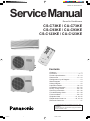
CS-C73KE / CU-C73KE
CS-C93KE / CU-C93KE
CS-C123KE / CU-C123KE
Contents
●
●
●
●
●
●
●
●
●
●
●
●
●
●
●
●
Features .......................................................... 1
Functions ................................................... 2 – 4
Product Specifications ............................. 5 – 10
Dimensions ............................................ 11 – 12
Refrigeration Cycle Diagram ......................... 13
Block Diagram ............................................... 14
Wiring Diagram .............................................. 15
Operation Details ................................... 16 – 23
Installation Information .......................... 24 – 25
2-way, 3-way Valves .............................. 26 – 32
Servicing Information ............................. 33 – 36
Troubleshooting Guide .......................... 37 – 38
Technical Data ....................................... 39 – 40
Exploded View ................................... 41, 43, 45
Replacement Parts List ..................... 42, 44, 46
Electronic Parts List ....................................... 47
1998 Matsushita Air-Conditioning Corp. Sdn. Bhd.
(183914D)
All rights reserved. Unauthorized copying and distribution is a violation of law.
Untitled-2
1
6/28/00, 5:22 PM
CS-C73KE
! WARNING
This service information is designed for experienced repair technicians only and is not designed for use by the general public. It does not contain
warnings or cautions to advise non-technical individuals of potential dangers in attempting to service a product. Products powered by electricity
should be serviced or repaired only by experienced professional technicians. Any attempt to service or repair the product or products dealt with
in this service information by anyone else could result in serious injury or death.
! PRECAUTION OF LOW TEMPERATURE
In order to avoid frostbite, be assured of no refrigerant leakage during the installation or repairing of refrigeration circuit.
Features
• High Efficiency
• Quality Improvement
– Gas leakage protection
– Prevent compressor reverse cycle
– 2-stage OLP to protect compressor
• Compact Design
• Comfort Enviroment
– 8 hours of sleep mode operation
– Air purifying filter with deodorizing function
to reduce dust, smoke and odours.
• Service Improvement
– Easy fan motor replacement procedure
• Operation Improvement
– Economy mode to reduce electrical power
consumption.
– Powerful mode to reaches the desired room
temperature quickly.
• Auto Restart
– Auto restart at random operation after power
failure
• Removable and Washable
Front Panel
• Long Installation Piping
– CS/CU–C73KE, CS/CU–C93KE, long piping up to 10
meter.
– CS/CU–C123KE, long piping up to 15 meter.
–1–
Untitled-1
1
6/29/00, 7:37 AM
MAC9512086C2
CS-C73KE
Functions
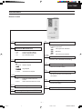
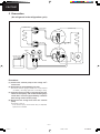
Remote Control
OFF / ON I
TEMP.
Operation OFF / ON
MODE
• Temperature Setting (16°C to 30°C)
• Automatic Operation
8 HI
2°C higher than standard
a
Operation Mode Selection
•
•
•
•
FAN SPEED
Automatic Operation Mode
Cooling Operation Mode
Soft Dry Operation Mode
Air Circulation Mode
AUTO
COOL
DRY
FAN
ON-TIMER
OFF-TIMER
AIR SWING
AUTO
•
MANUAL
Standard
2°C lower than standard
Timer Operation Selection
Low Speed
TIMER
Medium Speed
Time / Timer Setting
• Hours and minutes setting.
High Speed
SET
CANCEL
Automatic Fan Speed
Timer Operation Set / Cancel
• ON Timer and OFF Timer setting and
cancellation.
Airflow Direction Control
•
a
a
9 Lo
• 24-hour, OFF / ON Real Timer Setting.
Indoor Fan Speed Selection
• h j k
l
• h j k
lll
• h j k
lllll
• AUTOFAN
Room Temperature Setting
Automatic Airflow Direction
Control
Airflow Direction Manual Control
CLOCK
Clock Setting
• Current time setting.
POWERFUL
Powerful Mode Operation OFF/ON
SLEEP
ECONOMY
Sleep Mode Operation OFF / ON
Economy Mode Operation OFF/ON
–2 –
Untitled-1
2
6/29/00, 7:37 AM
MAC9512086C2
CS-C73KE
Functions
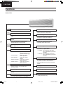
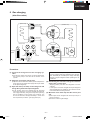
Indoor Unit
POWER I
Power Switch OFF / ON
AUTO
OFF / ON
Random Auto Restart Control
• Operation is restarted randomly after power
failure at previous setting mode.
Auto Operation Button
Anti-Freezing Control
• Used when the remote control cannot be
used.
• Anti-Freezing control for indoor heat
exchanger. (Cooling and Soft Dry)
Remote Control Signal Receiving
Sound
Sleep Mode Auto Control
• It can be controlled by pressing Auto
Operation Button for 10 seconds.
TEST RUN
OFF / ON
• Indoor Fan operates at low speed.
• Operation stops after 8 hours.
Operation Test Running / Pump
Down Switch
Indoor Fan Speed Control
• Used when test running or servicing.
Operation Indication Lamps (LED)
•
•
•
•
•
Lights up in operation,
blinks in Automatic
Operation Mode judging
SLEEP (Orange).....
Lights up in Sleep
Mode Operation
TIMER (Orange).....
Lights up in Timer
Setting
POWERFUL (Orange)..... Lights up in Powerful
Mode Operation
ECONOMY (Green)..... Lights up in Economy
Mode Operation
POWER
(Red)......
• High, Medium and Low.
• Automatic Fan Speed Mode
– Cooling : Fan rotates at Hi and Me
speed. Deodorizing control is
available.
– Soft Dry : Fan rotates at SLo and Lo
speed. Deodorizing control is
available.
Airflow Direction Control
• Automatic air swing and manual adjusted
by remote control for vertical airflow.
• Manually adjusted by hand for horizontal
airflow.
Operation Mode
Starting Current Control
• Cooling, Soft Dry, Air Circulation and
Automatic Mode.
Time Delay Safety Control
Powerful Operation
• Restarting is inhibited for appro. 3 minutes.
• Reaches the desired room temperature
quickly.
7 Minutes Time Save Control
Economy Operation
• Cooling Operation only.
• To reduce electrical power consumption.
–3–
Untitled-1
3
6/29/00, 7:37 AM
MAC9512086C2
CS-C73KE
Functions
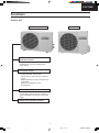
Outdoor Unit
CU-C123KE
CU-C73KE, CU-C93KE
Compressor Reverse Rotation
Protection Control
• To protect compressor from reverse
rotation when there is a instantaneous
power failure.
Overload Protector
• 2-Stage OLP to protect the compressor.
Overload Protector will trip when
– Temperature of compressor increases to
120°C.
– High temperature or high current flows to
compressor.
(Refer circuit diagram for OLP
characteristic)
60 Secs. Forced Operation Control
• Once the compressor is activated, it does
not stop within the first 60 secs. However, it
stops immediately with remote control stop
signal.
Outdoor Fan Operation Control
• Inner protector.
–4 –
Untitled-1
4
6/29/00, 7:37 AM
MAC9512086C2
CS-C73KE
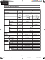
Product Specifications
Cooling Capacity
Moisture Removal
Power Source
Airflow Method
Unit
kW
Btu/h
s/h
Pint/h
Phase
V
Cycle
CS-C73KE
OUTLET
SIDE VIEW
TOP VIEW
CU-C73KE
2.05 - 2.00
7,000 - 6,830
1.3
2.7
Single
230 - 220
50
INTAKE
Air Volume
Indoor Air (Lo)
m3/min (cfm)
5.5 (190)
–
Indoor Air (Me)
m3/min (cfm)
6.3 (220)
–
Indoor Air (Hi)
m3/min (cfm)
7.0 (250)
–
Outdoor Air
m3/min (cfm)
–
22.2 (780)
dB (A)
High 33 - 32, Low 28 - 26
High 46 - 45
Noise Level
Electrical
Data
Input
W
600 - 550
Running Current
A
2.8 - 2.7
W/W
3.42 - 3.64
COP
Starting Current
Piping Connection Port
(Flare piping)
Pipe Size
(Flare piping)
Drain
Inner diameter
Hose
Length
Power Cord Length
Number of core-wire
Height
Dimensions
Width
Depth
Net Weight
Compressor
Type
Motor
Rated
Air Circulation
Motor
Fan
Speed
Type
Output
Type
Material
Type
Input
Rated Output
Low
Medium
High
12
A
inch
inch
inch
inch
mm
m
m
inch (mm)
inch (mm)
inch (mm)
lb (kg)
G ; Half Union 3/8"
L ; Half Union 1/4"
G (gas side) ; 3/8"
L (liquid side) ; 1/4"
12
0.7
2.0
3 (1.0 mm2)
10-31/32 (279)
31-15/32 (799)
7-15/32 (190)
20 (9.0)
–
–
–
Cross-flow Fan
AS + Glass Fiber 30%
Induction (4-poles)
29.0 - 27.0
10
835
945
1,055
W
W
W
rpm
rpm
rpm
G ; 3-way valve 3/8"
L ; 2-way valve 1/4"
G (gas side) ; 3/8"
L (liquid side) ; 1/4"
–
–
–
–
18-29/32 (480)
30-23/32 (780)
9-21/32 (245)
57 (26)
Rotary (1 cylinder)
rolling piston type
Induction (2-poles)
500
Propeller Fan
AES + Glass Fiber 16%
Induction (6-poles)
54.7 - 47.9
20
–
–
685
–5–
Untitled-1
5
6/21/00, 10:59 AM
MAC9512086C2
CS-C73KE
Product Specifications
Unit
Heat
Exchanger
Description
Tube material
Fin material
Fin Type
Row / Stage
FPI
Size (W × H × L)
Refrigerant Control Device
mm
Refrigeration Oil
(c.c)
Refrigerant (R-22)
Thermostat
Protection Device
Length
Capillary Tube Flow Rate
Inner Diameter
Material
Air Filter
Style
Capacity Control
Compressor Capacitor
Fan Motor Capacitor
g (oz)
mm
s/min
mm
µF, VAC
µF, VAC
CS-C73KE
CU-C73KE
Evaporator
Condenser
Copper
Copper
Aluminium
Aluminium
Louver Fin
Slit Fin
(Plate fin configuration, forced draft)
2 × 14
1 × 18
21
17
614 × 294 × 25.4
856 × 457.2 × 22
–
Capillary Tube
SUNISO 4GDID or
–
ATMOS M60 (260)
–
645 (22.8)
–
Electronic Control
–
2 Stage Overload Protector
–
450
–
7.9
–
1.2
P.P.
–
Honeycomb
Capillary Tube
–
20 µF, 370VAC
1.5 µF, 400VAC
1.2 µF, 400VAC
• Specifications are subject to change without notice for further improvement.
–6 –
Untitled-1
6
6/21/00, 10:59 AM
MAC9512086C2
CS-C73KE
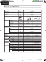
Product Specifications
Cooling Capacity
Moisture Removal
Power Source
Airflow Method
Unit
kW
Btu/h
s/h
Pint/h
Phase
V
Cycle
CS-C93KE
OUTLET
SIDE VIEW
TOP VIEW
CU-C93KE
2.75 - 2.65
9,390 - 9,050
1.6
3.4
Single
230 - 220
50
INTAKE
Air Volume
Indoor Air (Lo)
m3/min (cfm)
6.8 (240)
–
Indoor Air (Me)
m3/min (cfm)
7.3 (260)
–
Indoor Air (Hi)
m3/min (cfm)
8.7 (310)
–
Outdoor Air
m3/min (cfm)
–
22.2 (780)
dB (A)
High 37 - 36, Low 30 - 28
High 47 - 46
Noise Level
Electrical
Data
Input
W
800 - 770
Running Current
A
3.5 - 3.6
W/W
3.44 - 3.44
COP
Starting Current
Piping Connection Port
(Flare piping)
Pipe Size
(Flare piping)
Drain
Inner diameter
Hose
Length
Power Cord Length
Number of core-wire
Height
Dimensions
Width
Depth
Net Weight
Compressor
Type
Motor
Rated
Air Circulation
Motor
Fan
Speed
Type
Output
Type
Material
Type
Input
Rated Output
Low
Medium
High
16.4
A
inch
inch
inch
inch
mm
m
m
inch (mm)
inch (mm)
inch (mm)
lb (kg)
G ; Half Union 3/8"
L ; Half Union 1/4"
G (gas side) ; 3/8"
L (liquid side) ; 1/4"
12
0.7
2.0
3 (1.0 mm2)
10-31/32 (279)
31-15/32 (799)
7-15/32 (190)
20 (9.0)
–
–
–
Cross-flow Fan
AS + Glass Fiber 30%
Induction (4-poles)
35.5 - 33.0
15
925
995
1,185
W
W
W
rpm
rpm
rpm
G ; 3-way valve 3/8"
L ; 2-way valve 1/4"
G (gas side) ; 3/8"
L (liquid side) ; 1/4"
–
–
–
–
18-29/32 (480)
30-23/32 (780)
9-21/32 (245)
64 (29.0)
Rotary (1 cylinder)
rolling piston type
Induction (2-poles)
700
Propeller Fan
AES + Glass Fiber 16%
Induction (6-poles)
54.7 - 47.9
20
–
–
685
–7–
Untitled-1
7
6/21/00, 10:59 AM
MAC9512086C2
CS-C73KE
Product Specifications
Unit
Heat
Exchanger
Description
Tube material
Fin material
Fin Type
Row / Stage
FPI
Size (W × H × L)
Refrigerant Control Device
mm
Refrigeration Oil
(c.c)
Refrigerant (R-22)
Thermostat
Protection Device
Length
Capillary Tube Flow Rate
Inner Diameter
Material
Air Filter
Style
Capacity Control
Compressor Capacitor
Fan Motor Capacitor
g (oz)
mm
s/min
mm
µF, VAC
µF, VAC
CS-C93KE
CU-C93KE
Evaporator
Condenser
Copper
Copper
Aluminium
Aluminium
Louver Fin
Slit Fin
(Plate fin configuration, forced draft)
2 × 14
1 × 18
21
17
614 × 294 × 25.4
856 × 457.2 × 22
–
Capillary Tube
SUNISO 4GDID or
–
ATMOS M60 (320)
–
760 (26.8)
–
Electronic Control
–
2-Stage Overload Protector
–
1,040
–
9.0
–
1.5
P.P.
–
Honeycomb
Capillary Tube
–
30 µF, 370VAC
1.5 µF, 400VAC
1.2 µF, 400VAC
• Specifications are subject to change without notice for further improvement.
–8 –
Untitled-1
8
6/21/00, 10:59 AM
MAC9512086C2
CS-C73KE
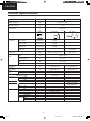
Product Specifications
Cooling Capacity
Moisture Removal
Power Source
Airflow Method
Unit
kW
Btu/h
s/h
Pint/h
Phase
V
Cycle
CS-C123KE
OUTLET
SIDE VIEW
TOP VIEW
CU-C123KE
3.65 - 3.52
12,500 - 12,000
2.1
4.4
Single
230 - 220
50
INTAKE
Air Volume
Indoor Air (Lo)
m3/min (cfm)
7.4 (260)
–
Indoor Air (Me)
m3/min (cfm)
8.0 (280)
–
Indoor Air (Hi)
m3/min (cfm)
9.0 (290)
–
Outdoor Air
m3/min (cfm)
–
32.2 (1130)
dB (A)
High 39 - 39, Low 34 - 33
High 49 - 48
Noise Level
Electrical
Data
Input
W
1,190 - 1,150
Running Current
A
5.3 - 5.4
W/W
3.07 - 3.06
COP
Starting Current
Piping Connection Port
(Flare piping)
Pipe Size
(Flare piping)
Drain
Inner diameter
Hose
Length
Power Cord Length
Number of core-wire
Height
Dimensions
Width
Depth
Net Weight
Compressor
Type
Motor
Rated
Air Circulation
Motor
Fan
Speed
Type
Output
Type
Material
Type
Input
Rated Output
Low
Medium
High
26
A
inch
inch
inch
inch
mm
m
m
inch (mm)
inch (mm)
inch (mm)
lb (kg)
G ; Half Union 1/2"
L ; Half Union 1/4"
G (gas side) ; 1/2"
L (liquid side) ; 1/4"
12
0.7
2.0
3 (1.0 mm2)
10-31/32 (279)
31-15/32 (799)
7-15/32 (190)
20 (9.0)
–
–
–
Cross-flow Fan
AS + Glass Fiber 30%
Induction (4-poles)
35.5 - 33.0
15
1,060
1,145
1,280
W
W
W
rpm
rpm
rpm
G ; 3-way valve 1/2"
L ; 2-way valve 1/4"
G (gas side) ; 1/2"
L (liquid side) ; 1/4"
–
–
–
–
21-1/4 (540)
27-17/32 (699)
11-7/32 (285)
82 (37)
Rotary (1 cylinder)
rolling piston type
Induction (2-poles)
1,100
Propeller Fan
AES + Glass Fiber 16%
Induction (6-poles)
72.0 - 68.0
25
–
–
785
–9–
Untitled-1
9
6/21/00, 10:59 AM
MAC9512086C2
CS-C73KE
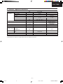
Product Specifications
Unit
Heat
Exchanger
Description
Tube material
Fin material
Fin Type
Row / Stage
FPI
Size (W × H × L)
Refrigerant Control Device
mm
Refrigeration Oil
(c.c)
Refrigerant (R-22)
Thermostat
Protection Device
Length
Capillary Tube Flow Rate
Inner Diameter
Material
Air Filter
Style
Capacity Control
Compressor Capacitor
Fan Motor Capacitor
g (oz)
mm
s/min
mm
µF, VAC
µF, VAC
CS-C123KE
CU-C123KE
Evaporator
Condenser
Copper
Copper
Aluminium
Aluminium
Louver Fin
Slit Fin
(Plate fin configuration, forced draft)
2 × 14
1 × 20
21
18
614 × 294 × 25.4
782.9 × 508 × 22
–
Capillary Tube
SUNISO 4GDID or
–
ATMOS M60 (410)
–
815 (28.8)
–
Electronic Control
–
2-Stage Overload Protector
–
535
–
17.0
–
1.7
P.P.
–
Honeycomb
Capillary Tube
–
30 µF, 370VAC
1.5 µF, 400VAC
1.5 µF, 400VAC
• Specifications are subject to change without notice for further improvement.
– 10 –
Untitled-1
10
6/21/00, 10:59 AM
MAC9512086C2
CS-C73KE
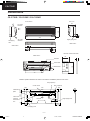
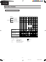
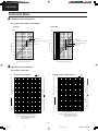
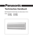
Dimensions
CS-C73KE / CS-C93KE / CS-C123KE
Unit : mm
<Front View>
190
60
36
279
Air intake
direction
799
Left piping
hole
Air outlet
direction
Right piping hole
<Side View>
60
<Side View>
58
60
83
Remote control transmitter
<Back View>
65
18
GAS SIDE
LIQUID SIDE
65
DRAIN PORT
122
TEMP
C
POWERFUL
425
48
Relative position between the indoor unit and the installation plate <Front View>
Slot (2 places)
Slot (2 places)
Centre notch
(40)
17.8
100
350
100
Arrow
Arrow
Centre
Right piping hole
4
Indoor unit
external
dimensions
line
16.5
550
257.2
Installation
plate
(49)
710
(60)
(99)
Left piping hole
– 11 –
Untitled-1
11
6/21/00, 10:59 AM
MAC9512086C2
CS-C73KE
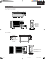
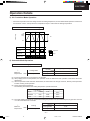
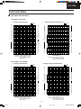
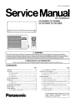
Dimensions
54
93
780
27.5
CU-C73KE / CU-C93KE
245
480
467
2-way valve at
Liquid side
(High Pressure)
77 67
3-way valve at
Gas side
(Low Pressure)
570
105
280
312
13
105
CU-C123KE
699
100
69
500
99
(52)
32
Space necessary for
installation
(120)
162
10 cm
10 cm
100 cm
Anchor Bolt Pitch
323 x 500
285
540
7.5
2-Way Valve at Liquid side
(High Pressure)
11
67
67
3-Way Valve at Gas side
(Low Pressure)
(323)
347
– 12 –
Untitled-1
12
6/21/00, 10:59 AM
MAC9512086C2
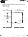
CS-C73KE
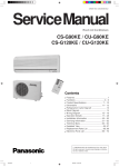
Refrigeration Cycle Diagram
CS-C73KE / CU-C73KE
CS-C93KE / CU-C93KE
CS-C123KE / CU-C123KE
INDOOR
OUTDOOR
CAPILLARY
TUBE
2-WAY
VALVE
INTAKE
AIR
TEMP.
SENSOR
HEAT
EXCHENGER
TEMP.
SENSOR
HEAT EXCHANGER
(EVAPORATOR)
HEAT EXCHANGER
(CONDENSER)
3-WAY
VALVE
COMPRESSOR
– 13 –
Untitled-1
13
6/21/00, 10:59 AM
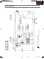
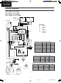
MAC9512086C2
SINGLE PHASE
AC 220-230V
50Hz
6/28/00, 4:11 PM
TRANSFORMER
ZNR2
FAN
MOTOR
RY-H
RY-SHI
Indicates the electronic control unit.
SSR
4C
C-FM
RY-M
5C
9C
"C" Indicates the number of core wires. (Example:6C=6 core wires).
ZNR1
THERMAL
FUSE
(102°C)
CONTROL BOX
TEMP. FUSE
(113°C)
FUSE
3.15A
CR1
RY-PWR
ELECTRONIC CONTROLLER
CR2
MAIN
POWER SWITCH
CR3
14
CR4
Untitled-1
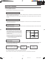
Indoor Unit
CS-C73KE / CU-C73KE
CS-C93KE / CU-C93KE
CS-C123KE / CU-C123KE
INTAKE AIR
TEMP. SENSOR
PIPE TEMP.
SENSOR
STEPPING
MOTOR
INDICATOR
P.C.B.
RECEIVER
P.C.B.
1
2
2
WIRELESS
REMOTE CONTROL
TRANSMITTER
1
C73KHBLD.DWG
CS/CU-C73KH/C93KH
J9990114
COMPRESSOR
FAN MOTOR
FUSE
3.15A
OVERLOAD
PROTECTOR
Outdoor Unit
CS-C73KE
Block Diagram
– 14 –
MAC9512086C2
CS-C73KE
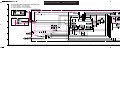
Wiring Diagram
CS-C73KE / CU-C73KE
CS-C93KE / CU-C93KE
CS-C123KE / CU-C123KE
WIRELESS
REMOTE
CONTROL
ELECTRONIC
CONTROLLER
(RECEIVER)
REMOTE
CONTROL No.
B
A
4 5 6 7
CN-DISP(W)
5
4
3
2
1
REMARKS:
B
: BLUE
BR : BROWN
BL
: BLACK
W
: WHITE
R
: RED
O
: ORANGE
P
: PINK
Y/G : YELLOW/
GREEN
W
W
6
W
W
W
W
3
1
8
9
R
FAN
MOTOR
1
PUMP DOWN SW
(TEST RUN)
CAPACITOR
Y
W
3
O
B
CN-C
(G)
BR
3
2
1
2
ELECTRONIC CONTROLLER
W
1
BR
MAIN SW
B
W
BR
W
W
Y/G
3
4
CN-DISP(W)
CN-RCV (W)
220-230V, 50Hz
POWER SUPPLY CORD
2
DISPLAY LAMP
3
5
7
CN-FM(G)
1
RY-M
2
3
4
Y
P
ZNR2
AIR
SWING
MOTOR
W
1
SENSOR
(PIPE TEMP.)
TRANSFORMER
W
Resistance of Indoor Fan Motor Windings
MODEL
CS-C73KE CS-C93KE CS-C123KE
CONNECTION
CWA92288 CWA92289 CWA92290
YELLOW-BLUE
536.5
449.5
457.4
2
3
BL
4
(W)
BL
AC
CN-TH(Y)
ELECTRONIC
CONTROLLER
R
O
SENSOR
(INTAKE AIR TEMP.)
ZNR1
THERMAL
FUSE
(113°C)
L
SSR
FUSE(3.15A)
P
BR
5
RY-PWR
CN-STM(G)
RY-SHI
1
RY-H
CR4
CR3
CR2
CR1
AUTO SW
YELLOW-BROWN
77.1
87.7
56.1
BROWN-ORANGE
43.9
56.1
61.2
ORANGE-WHITE
42.7
18.6
25.3
WHITE-RED
111.4
124.1
142.5
R
W
R
1
W
3
R
Resistance of Outdoor Fan Motor Windings
CN-FUSE(B)
R
MODEL
CU-C73KE
CU-C93KE
CU-C123KE
BL
Y/G
INDOOR UNIT
TERMINAL
1 2
OUTDOOR UNIT
TERMINAL
1 2
B
THERMAL
FUSE
(102°C)
CWA95238
@
CWA95378
310.0 Ω
@
174.5 Ω
YELLOW-RED
409.8 Ω
@
331.0 Ω
YELLOW
Y
GRY
CONNECTION
BLUE-YELLOW
Resistance of Compressor Windings
MODEL
BLUE
FAN MOTOR
RED
CU-C93KE
CU-C123KE
C-R
5.382 Ω
3.941 Ω
2.211 Ω
C-S
5.328 Ω
3.499 Ω
2.924 Ω
B
R
B
CU-C73KE
CONNECTION 2RS110D5CA04 2PS146D5BA04 2KS224D5CA02
BRAND MARK
COMPRESSOR TERMINAL
FUSE 3.15A
R
J9890634
CS/CU-C73KE/C93KE/C123KE
C73KE07.DWG
B
B
OVER LOAD
PROTECTOR
CAPACITOR
Y
COMPRESSOR
CAPACITOR
– 15 –
Untitled-1
15
6/28/00, 4:11 PM
MAC9512086C2
CS-C73KE
Operation Details
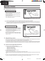
1) Cooling Mode Operation
Cooling in operation according to Remote Control setting.
Time Delay Safety Control (3 minutes)
• When the compressor is stopped by Power Switch or Remote Control, it restarts after 3 minutes when the Power
Switch or Remote Control is turned ON.
• When the setting temperature is reached during cooling operation, the compressor stops and it will not start for 3
minutes.
7 minutes Time Saved Control
• The compressor will start automatically if it has stopped for 7 minutes even if the room temperature is below the
compressor ON temperature.
Starting Current Control
• When the compressor, outdoor fan motor & indoor fan motor are simultaneously started, the indoor fan motor will
operate 1.6 second later.
Anti-Freezing Control
• If the temperature of the indoor heat exchanger
falls continously below 2°C for 4 minutes or more,
the compressor turns off to protect the indoor heat
exchanger from freezing. The fan speed setting
remains the same.
Indoor Heat
Exchanger
Temperature
(°C)
10
Recovery
4 min
• Compressor recommences when the indoor heat
exchanger temperature rises to 10°C (Recovery).
* 3 minutes waiting of Time Delay Safety Control
is valid for Cooling Operation.
2
Compressor OFF
Compressor Reverse Rotation
Protection Control
• If the compressor is operating continuously for 5 minutes or longer and the temperature difference between intake
air and indoor heat exchanger is 2.5˚C or less for 2 minutes, compressor will stop and restart automatically.
(Time Delay Safety Control is valid).
• Compressor starts for > 5 minutes
• ∆ T < 2.5˚C for 2 minutes
➡
Compressor
OFF
➡
Compressor
restarts
(3 minutes waiting)
∆ T = Intake air temperature – Indoor heat exchanger temperature
This is to protect reverse rotation of the compressor when there is a instantaneous power failure.
– 16 –
Untitled-1
16
6/28/00, 4:11 PM
MAC9512086C2
CS-C73KE
Operation Details
Automatic Fan Speed Mode
When Automatic Fan Speed is selected at Remote Control during cooling operation.
•
Fan speed rotates in the range of Hi to Me.
•
Deodorizing Control.
.
.✕
.. 1
.
.✕
.. 2
SLo
Indoor
Fan
SLo
SLo
stop
40"
20"
30"
SLo
stop
stop
160"
40"
30"
Comp.
ON
OFF
ON
* 1 Fan Speed is Hi until the compressor stops (when the room temperature reaches
setting temperature).
* 2 Fan Speed is Me after the compressor restarts.
* SLo: Indoor Fan rotates at 4 second intervals at low speed.
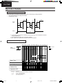
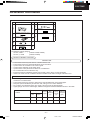
Cooling Operation Time Diagram
ab c d e f g h i j k l mn o p q r s t u v wx yz
Intake
1.5K
Temperature
ON
Operation
OFF
Stop
Set Temp.
10°C
Pipe temperature
2°C
Basic Time
1’
3’
1’
7’
1’
4’
Compressor
Indoor Fan
Outdoor Fan
Operation LED
<Description of operation>
d – g : Time Delay Safety Control (waiting for 3 minutes)
g – h : 60 sec. Forced Operation
h – o : 7 min. Time Saved Control
q–t
: Anti Freezing Control
– 17 –
Untitled-1
17
6/28/00, 4:11 PM
MAC9512086C2
CS-C73KE
Operation Details
2) Soft Dry Mode Operation
• The unit starts cooling operation until the room temperature reaches the setting temperature set on the Remote
Control, and then Soft Dry operation will start.
• During Soft Dry operation, the Indoor Fan will operate and stop at 4-second intervals at low speed.
• The operation will be switched on and off for up to 10 minutes “ON” and 6 minutes “OFF”. Once Soft Dry operation is turned off, it stops for 6 minutes.
Time Delay Safety Control
• Once the compressor stops, it will not start for 3 minutes during Cooling operation.
Starting Current Control
• Same as Starting Current Control for Cooling Mode operation.
Anti-Freezing Control
• Same as Anti-Freezing Control for Cooling Mode operation. (For Soft Dry region, 6 minutes waiting is valid during
compressor stops.)
Compressor Reverse Rotation
Protection Control
• Same as Compressor Reverse Rotation Protection Control for Cooling Mode Operation. (For Soft Dry region, 6
minutes waiting is valid during compressor stops.)
Automatic Fan Speed Mode
When Automatic Fan Speed is selected at Remote Control during Soft Dry Operation.
• Fan speed rotates at SLo and Lo speed.
• Deodorizing Control.
SLo
Indoor
Fan
Lo
SLo
stop
stop
stop
40"
6'
40"
ON
ON
OFF
COMP
* SLo: Indoor Fan rotates at 4-second intervals at low speed.
– 18 –
Untitled-1
18
6/28/00, 4:11 PM
MAC9512086C2
CS-C73KE
Operation Details
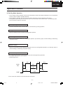
Soft Dry Operation Time Diagram
ab c d e f g h i j k l mn o pq r s t u v
Intake Air
Temperature
Cooling ON
1.5°C
Set Temp.
1.0°C
Cooling OFF
Soft Dry ON
Soft Dry OFF, ON
10°C
Indoor
Heat Exchanger
Temp.
2°C
6’ 1’
Basic Time
6’
1’
6’ 1’
4’
6’ 1’ 6’
Compressor
Indoor Fan
SLo SLo
SLo SLo
Lo SLo SLo
SLo SLo SLo
SLo
SLo
Outdoor Fan
Operation LED
<Description of operation>
a – c, p~r
: Cooling Operation
c – p, r – v : Soft Dry Operation
e–f
: Soft Dry OFF
j–l
: 60 sec. Forced Operation
q–t
: Anti Freezing Control
Operation
Stop
– 19 –
Untitled-1
19
6/28/00, 4:11 PM
MAC9512086C2
CS-C73KE
Operation Details
3) Air Circulation Mode Operation
• When the temperature near the ceiling reaches the setting temperature, Air Circulation Mode operation commences
at low airflow volume. It stops when the temperature drops to 2°C below the setting temperature.
Air Circulation Mode Operation Time Diagram
a
b
c
d
e
Intake Air Temp.
ON
Setting
Temp.
2°C
OFF
Compressor
Lo
Indoor Fan
Lo
Operation
Outdoor Fan
Stop
Operation
Indication LED
4) Automatic Mode Operation
Standard for Determining Operation Mode
↑
Intake Air
Temperature
Setting Temperature (Standard)
23°C
Cooling Mode
Cooling Mode
25°C
Soft Dry Mode
Soft Dry Mode
22°C
(a) Indoor fan operates at Lo fan speed for 20 seconds.
(b) After judging indoor air temperature, the operation mode is determined and operation continued at the mode
determined.
(c) After the operation mode has been determined, the mode does not change. However, Soft Dry mode operation
includes Cooling mode operation.
(d) Room temperature adjustment.
The following are added to the setting temperature specified as above.
Cooling
Soft Dry
Higher
→
+2°C
27°C
24°C
Standard
→
±0°C
25°C
22°C
Lower
→
–2°C
23°C
20°C
(e) The mode judging temperature and standard setting temperature can be increased by 2°C, by open the circuit of
J X 2 at indoor electronic controller.
↑
Intake Air
Temperature
Setting Temperature (Standard)
25°C
Cooling
Cooling Mode
27°C
Soft Dry
Soft Dry Mode
24°C
– 20 –
Untitled-1
20
6/28/00, 4:11 PM
MAC9512086C2
CS-C73KE
Operation Details
5) Sleep Mode Auto Operation
Cooling or Soft Dry Operation
When you press the SLEEP Mode, the following movement will start to avoid overcooling.
SETTING
TEMPERATURE
• When the room temperature reaches the setting
temperature or after 1 hour of operation, sleep shift
operation starts and the airflow volume will automatically change to low.
Approx. 0.5°C increase
TEMP.
Approx. 0.5°C increase
1 hour
0 – 1 hour
• The setting temperature will be risen by 0.5°C at the
Sleep Operation button is pressed.
start of operation and by 0.5°C one hour later.
Approx. 8 hours after
sleep shift operation
starts, stops automatically
TIME
Sleep shift Operation
starts.
• The operation will stop after 8 hours.
6) Powerful Mode Operation.
• Purpose of this operation is to obtain the setting temperature quickly.
• When the Powerful Mode is set, the set temperature will be automatically decreased 3°C against the present
setting temperature.
This operation automatically will be running under Super High Fan speed.
• Vertical Airflow Direction:– In 'manual' setting, the vane will automatically shift down 10° lower than previous setting.
– In 'Auto' setting, the vane will automatically swing up and down. However the lower limit will be shifted 10°
downward.
• Powerful Mode will operate for 15 minutes only.
• Powerful Mode will stop if:– Powerful mode button is pressed again.
– Stopped by ON/OFF switch.
– Timer OFF activates.
– Economy mode button is pressed.
– Sleep mode is pressed.
– Operation mode is changed.
7) Economy Mode Operation.
• Purpose of this operation is to save or reduced electrical power consumption of the room air conditioner.
• When the Economy Mode is set, the set temperature will be automatically increased 0.5°C against the present
setting temperature. This operation automatically will be running under Random Fan speed.
(Refer operation detail no. 9 )
• Vertical Airflow Direction:In 'manual' or 'Auto' setting, the vane will automatically change to Auto Air Swing.
• Economy Mode will stop if:– Economy mode button is pressed again.
– Stopped by ON/OFF switch.
– Timer–off activates.
– Powerful mode button is pressed.
– Auto or Manual air swing button is pressed.
– 21 –
Untitled-1
21
6/28/00, 4:11 PM
MAC9512086C2
CS-C73KE
Operation Details
– Fan Speed control button is pressed.
– Sleep mode button is pressed ON.
– Operation mode is changed.
8) Random Auto Restart Control
• If there is a power failure, operation will be automatically restarted after 3 to 5 1/2 minutes when the power is
resumed.
It will start with previous operation mode and airflow direction.
• Restart time is decided randomly using 4 parameter:Intake air temperature, setting temperature, fan speed and Air Swing Blade position.
• Auto Restart Control is not available when Timer or Sleep Mode is set.
• This control can be omitted by open the circuit of J X 1. (Refer Circuit Diagram)
9) Indoor Fan Speed Control
• Auto Fan Speed Control
When set to Auto Fan Speed, the fan speed is adjusted between maximum and minimum setting as shown in the
table.
• Manual Fan Speed Control
Basic fan speed adjustment (3 settings, from Lo to Hi) can be carried out by using the Fan Speed selection
button.
SHi
Manual Fan Speed
Cooling
Mode
Normal
Powerful
Hi
Me
Lo
t
t
t
SLo
t
t
Economy
Auto Fan Speed
t
Normal
Powerful
t
t
t
Economy
Soft Dry Mode
Air Circulation Mode
Random Speed
Normal
t
t
Powerful
t
t
Economy
t
t
Normal
t
Powerful
Economy
Can setting by Remote Control
Cannot setting by Remote Control
* SLo: Indoor Fan rotates at 4-second intervals at Low speed.
* Lo, Lo¯ or Lo¯¯ Fan Speed is operated randomly during Random Fan Speed.
Random Fan Speed
Random
A
B
C
Fan Speed
LO
LO¯
LO¯¯
Time
10"
4.5" 0.5" 4.5" 0.5"
Fan Motor
ON
ON OFF ON OFF ON OFF ON OFF
4"
1"
4"
1"
– 22 –
Untitled-1
22
6/28/00, 4:11 PM
MAC9512086C2
CS-C73KE
Operation Details
10) Airflow Direction Control
Horizontal
Airflow Direction Auto-Control
Upper limit
36°
• When set a Airflow Direction Auto-Control with
remote control, the louver swings up and down as
shown in the diagram.
• The louver does not swing when the Indoor Fan
stops during operation.
• When stopped with remote control, the discharge
vent is closed with the louver.
Swing up and down
61°
Lower limit for
Cooling Mode and
Soft Dry Mode
Lower limit for Air Circulation Mode
* The left and right airflow direction louvers can be
adjusted manually.
* 1 There is no swinging while indoor fan is stopped during Cooling and Soft Dry operation.
* 2 In Air Circulation operation, when the intake air temperature reaches set temperature, the airflow direction is
changed from upper limit to lower limit. When the intake air temperature falls to 2°C lower than set temperature,
the airflow direction is changed from lower limit to upper limit.
Horizontal
Airflow Direction Manual Control
36°
• When the manual Airflow Direction Selection Button is pressed, the automatic airflow is released
and the airflow direction louver move up and down
in the range shown in the diagram.
The louver can be adjusted by pressing the button
to the desired louver position.
• When the remote control is used to stop the operation, the discharge vent is closed with airflow
direction louver.
Upper limit /0°
9°
18°
61°
27°
Lower limit for
Cooling Mode and
Soft Dry Mode /36°
Lower limit for Air Circulation Mode
The louver can be adjusted with in a range of
“Manual Airflow Direction Selection Button” is
pressed.
* The left and right airflow direction louvers can be
adjusted manually.
11) Delay ON Timer Control
• When the Delayed ON Timer is set by using the remote control, the unit will start operate slightly before the set time,
so that the room will reach nearly to the set temperature by the desired time.
• For Cooling and Soft Dry mode, the operation will start 15 minutes before the set time.
• For Automatic mode, the indoor fan will operate at Lo speed for 20 seconds, 15 minutes before the set time to detect
the intake air temperature to determine the operation mode. The operation indication lamp will blink at this time.
12) Remote Control Signal Receiving Sound
• Peep sound (Long) will be heard when:– Stopping the Air Conditioner using ON/OFF switch.
– Stopping the Sleep Mode.
– Stopping the Powerful Mode.
– Stopping the Economy Mode.
• Pep sound (Short) will be heard for others.
• To switch off the peep sound
press the "Auto Operation Button" continuously for 10 seconds or more.
Repeat the above if you want to switch ON the beep sound or switch OFF and ON back the power switch at the indoor
unit.
* However, if the "Auto Operation Button" have been pressed the Automatic cooling operation will be activated.
If you do not require this operation, you may change it by using the remote control.
– 23 –
Untitled-1
23
6/28/00, 4:11 PM
MAC9512086C2
CS-C73KE
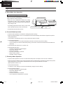
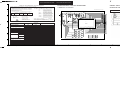
Installation Information
Attached accessories
No.
Accessories part
Qty.
Installation plate
No.
6
1
1
7
Installation plate fixing screw
2
3
Qty.
Band
2
Vinyl tape
3
Vinyl tape
4
8
Remote control
TE MP
POW
OFF
ERF
UL
Battery
/ON
1
1
2
4
5
Accessories part
Air purifying filter
2
Accessories: Flaring piping kit
CZ-3F5, 7AEN
(CS/CU-C73KE, C93KE)
CZ-4F5, 7, 10AN
(CS/CU-C123KE)
SELECT THE BEST LOCATION
INDOOR UNIT
•
•
•
•
•
•
•
•
There should not be any heat source or steam near the unit.
There should not be any obstacles blocking the air circulation.
A place where air circulation in the room is good.
A place where drainage can be easily done.
A place where noise prevention is taken into consideration.
Do not install the unit near the door way.
Ensure the spaces indicated by arrows from the wall, ceiling, fence or other obstacles.
Indoor unit of this room air conditioner shall be installed on the wall in a height of at least 2.3 m.
OUTDOOR UNIT
• If an awning is built over the unit to prevent direct sunlight or rain, be careful that heat radiation from the
condenser is not obstructed.
• There should not be any animal or plant which could be affected by hot air discharged.
• Keep the spaces indicated by arrows from wall, ceiling, fence or other obstacles.
• Do not place any obstacles which may cause a short circuit of the discharged air.
• If piping length is over the rated length, additional refrigerant should be added as shown in the table.
Piping size
MODEL
Max.
Common
Length Elevation
(m)
Max.
Piping Additional
Length Refrigerant
(g/m)
(m)
Gas
Liquid
C73KE/C93KE
3/8"
1/4"
7.5
5
10
10
C123KE
1/2"
1/4"
7.5
5
15
10
– 24 –
Untitled-2
24
6/28/00, 4:16 PM
MAC9512086C2
CS-C73KE
Installation Information
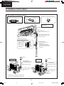
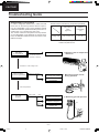
Indoor / Outdoor unit installation diagram
Length of power supply cord
about 1.1 m
< <
Piping direction
about 1.8 m
<
Attention not to bend up drain hose
(Front side)
Right
Right
rear
Left
Right bottom rear
<
Left
Left bottom
Installation parts you must
purchase (*)
5 cm or
more
Installation plate 1
Sleeve (*)
Bushing-Sleeve (*)
Putty, (Gum Type Sealer) (*)
5 cm or
more
Air purifying filter 5
Bend the pipe as closely on the
wall as possible, but be careful
that it doesn’t break.
(Left and right are identical)
Insulation of piping connection
•
•
Carry out insallation
after checking for gas
leaks.
After securing with
three of the vinyl
tape 7, wrap with
vinyl tape 8.
Vinyl tape (Wide) (*)
• Apply after carrying out a
drainage test.
• To carry out the drainage
test, remove into the air filters
and pour water into the heat
exchanger.
Vinyl tape
8
Vinyl tape 7
Saddle (*)
cm
10 ore
or m
Saddle (*)
CU-C73KE
CU-C93KE
CU-C123KE
Connecting cable
(3-CORE WIRE/1.5 mm2)
Locally approved cable.
cm
10 ore
or m
Additional drain hose (*)
10 cm
or more
Connecting cable
(3-CORE WIRE/1.5 mm2)
Locally approved cable.
Additional drain hose (*)
1/4" Liquid side piping (*)
m
10 c re
o
or m
10 cm
or more
Gas side piping (*)
1/2"
1/4" Liquid side piping (*)
m
10 c re
o
or m
Gas side piping (*)
3/8"
Vinyl tape (*)
(Narrow)
• This illustration is for explanation purposes only.
The indoor unit will actually face a different way.
– 25 –
Untitled-2
25
6/28/00, 4:16 PM
MAC9512086C2
CS-C73KE
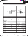
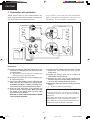
2-way • 3-way Valve
2-way Valve (Liquid Side)
3-way Valve (Gas Side)
Valve cap
Flare nut
Hexagonal wrench (4 mm)
Open position
Closed position
To
piping
connection
Flare nut
Open position
Closed position
To
piping
connection
Pin
Service
port cap
To outdoor unit
To outdoor unit
Service port
Works
Shaft Position
Shaft Position
Service Port
Shipping
Close
(With valve cap)
Closed
(With valve cap)
Closed
(With cap)
Evacuation
Installation and
Re-installation
Closed
(Counter-Clockwise)
Closed
(Clockwise)
Open
(Push-pin)
Operation
Open
(With valve cap)
Open
(With valve cap)
Closed
(With cap)
Pumping down
(Transferring)
Closed
(Clockwise)
Open
(Counter-clockwise)
Open
(Connected manifold
gauge)
Evacuation
(Servicing)
Open
Open
Open
With vacuum pump
Gas charging
(Servicing)
Open
Open
Open
(With charging cylinder)
Open
Open
Open
(Connected manifold
gauge)
Open
Open
Open
(Connected manifold
gauge)
Pressure check
(Servicing)
Gas releasing
(Servicing)
– 26 –
Untitled-3
26
6/28/00, 4:19 PM
MAC9512086C2
CS-C73KE
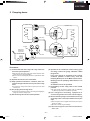
1 Evacuation of Installation
WHEN INSTALLING AN AIR CONDITIONER, BE
SURE TO EVACUATE THE AIR INSIDE THE INDOOR
UNIT AND PIPES in the following procedure.
(Indoor unit)
If air remain in the indoor unit and refrigeration
pipes, it will affect the compressor, reduce to cooling capacity, and could lead to a malfunction.
(Liquid side)
(Outdoor unit)
2-way valve
Closed
(Gas side)
3-way valve
OPEN
Closed
Vacuum pump
Lo
Hi
CLOSE
Procedure:
(1) Connect a charging hose with a push pin to the
Low side of a charging set and the service port
of a 3-way valve.
●
Be sure to connect the end of the charging hose
with the push pin to the service port.
(5) Disconnect the charging hose from the vacuum
pump and from the service port of the
3-way valve.
(2) Connect the centre hose of the charging set
to a vacuum pump.
(7) Remove the valve caps of the 2-way valve
and the 3-way valve. Position both of the valves to
“open” using a hexagonal wrench (4 mm).
(6) Tighten the service port cap at a torque of
18 N•m with a torque wrench.
(3) Turn on the power switch of the vacuum pump and
make sure that the needle in the gauge moves
from 0 MPa (0 cmHg) to –0.1 MPa (–76 cmHg). Then
evacuate the air for approximately ten minutes.
(8) Mount the valve caps onto the 2-way and 3-way
valves.
●
Be sure to check for gas leakage.
(4) Close the Low side valve of the charging set
and turn off the vacuum pump. Make sure that
the needle in the gauge does not move after
approximately five minutes.
BE SURE TO TAKE THIS PROCEDURE IN ORDER
TO AVOID GAS LEAKAGE.
Caution
If gauge needle does not move from 0 cmHg to
–76 cmHg in step (3) above, take the following
measures:
If the leaks stop when the piping connections are
tightened further, continue working from step (3).
If the leaks do not stop when the connections are
retightened, repair the location of the leak.
– 27 –
Untitled-3
27
6/28/00, 4:19 PM
MAC9512086C2
CS-C73KE
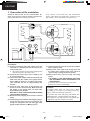
2 Pumping down
(Indoor unit)
(Liquid side)
(Outdoor unit)
2-way valve
Closed
(Gas side)
3-way valve
CLOSE
Open
Refrigerant
Reclaiming
Equipment
Lo
Hi
CLOSE
Procedure:
(1) Confirm that both the 2-way and 3-way valves are
set to the opened position.
●
●
Remove the valve stem caps and confirm that the valve
stems are in the opened position.
Be sure to use a hexagonal wrench to operate the valve
stems.
(2) Operate the unit for 10 to 15 minutes.
(3) Stop operation and wait for 3 minutes, then connect the charge set to the service port of the 3-way
valve.
●
Connect the charge hose with the push pin to the Gas
service port.
(4) Air purging of the charge hose.
●
(6) Operate the air conditioner at the cooling cycle
and stop it when the gauge indicates 0 MPa
(0 kg/cm2G).
If the unit cannot be operated at the cooling
condition (weather is rather cool), short the
Pumping Down pins on the Main Control P.C.B.
(Simply press the pumping down button if it is
equipped.)
So that the unit can be operated.
(7) Immediately set the 3-way valve to the closed
position.
●
Open the low-pressure valve on the charge set slightly to
purge air from the charge hose.
(5) Set the 2-way valve to the closed position.
Do this quickly so that the gauge ends up indicating
0.1 MPa (1 kg/cm2G) to 0.3 MPa (3 kg/cm2G)
(8) Use refrigerant reclaiming equipment to
collect refrigerant from indoor unit and pipes.
(9) Disconnect the charge set, and mount the 2-way
and 3-way valve’s stem caps and the service port
caps.
●
●
Use a torque wrench to tighten the service port cap to a
torque of 18 N•m.
Be sure to check for gas leakage.
(10) Disconnect pipes from indoor unit and outdoor unit.
– 28 –
Untitled-3
28
6/28/00, 4:19 PM
MAC9512086C2
CS-C73KE
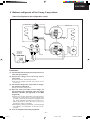
3 Evacuation of Re-installation
If air remain in the indoor unit and refrigeration
pipes, it will affect the compressor, reduce to cooling capacity, and could lead to a malfunction.
WHEN RE-INSTALLING AN AIR CONDITIONER, BE
SURE TO EVACUATE THE AIR INSIDE THE INDOOR
UNIT AND PIPES in the following procedure.
(Indoor unit)
(Liquid side)
(Outdoor unit)
2-way valve
Closed
(Gas side)
3-way valve
OPEN
Closed
Vacuum pump
Lo
Hi
CLOSE
Procedure:
(1) Connect a charging hose with a push pin to the
Low side of a charging set and the service port
of the 3-way valve.
●
Be sure to connect the end of the charging hose
with the push pin to the service port.
(2) Connect the center hose of the charging set
to a vacuum pump.
(3) Turn on the power switch of the vacuum pump and
make sure that the needle in the gauge moves
from 0 MPa (0 cmHg) to –0.1 MPa (–76 cmHg).
Then evacuate the air for approximately ten
minutes.
(4) Close the Low side valve of the charging set
and turn off the vacuum pump. Make sure that
the needle in the gauge does not move after
approximately five minutes.
BE SURE TO TAKE THIS PROCEDURE IN ORDER
TO AVOID GAS LEAKAGE.
(5) Disconnect the charging hose from the vacuum
pump .
(7) Tighten the service port cap at a torque of 18N•m
with a torque wrench.
(8) Remove the valve caps of the 2-way valve and
the 3-way valve. Position both of the valves to
"open" using a hexagonal wrench (4 mm).
(9) Mount valve caps onto the 2-way and 3-way
valves.
● BE SURE TO USE REFRIGERANT RECLAIMING EQUIPMENT WHILE DISCHARGING THE
REFRIGERANT.
● Purge the air from charge set’s centre hose.
● Be sure to check for gas leakage.
Caution
If gauge needle does not move from 0 MPa
(0 cmHg) to –0.1 MPa (–76 cmHg) in step (3)
above, take the following measures:
If the leaks stop when the piping connections are
tightened further, continue working from step (3).
If the leaks do not stop when the connections are
retightened, repair the location of the leak.
(6) Charge the pipes and indoor unit with gas refrigerant from 3-way valve service port, and then discharge the refrigerant until low side (gas side)
gauge needle indicates 0.3 MPa (3 kg/cm2)
– 29 –
Untitled-3
29
6/28/00, 4:19 PM
MAC9512086C2
CS-C73KE
4 Balance refrigerant of the 2-way, 3-way valves
(Lack of refrigerant in the refrigeration cycle)
(Indoor unit)
(Liquid side)
(Outdoor unit)
2-way valve
Open
(Gas side)
3-way valve
OPEN
Open
Lo
Refrigerant
Reclaiming
Equipment
Hi
CLOSE
Procedure:
(1) Confirm that both the 2-way and 3-way valves are
set to the open position.
(2) Connect the charge set to the 3-way valve’s
service port.
●
●
Leave the valve on the charge set closed.
Connect the charge hose with the push-pin to the
service port.
(3) Connect the charge set’s centre hose to refrigerant reclaiming equipment.
●
Purge the air from charge hose.
(4) Open the valve (Low side) on the charge set
and discharge the refrigerant until the gauge
indicates 0.05 MPa (0.5 kg/cm2G) to 0.1 MPa
(1 kg/cm2G).
●
●
If there is no air in the refrigeration cycle (the pressure
when the air conditioner is not running is higher than
0.1 MPa (1 kg/cm2G), discharge the refrigerant until
the gauge indicates 0.05 MPa (0.5 kg/cm2G) to 0.1
MPa (1 kg/cm2G). If this is the case, it will not be
necessary to apply a evacuation.
Discharge the refrigerant gradually; if it is discharged
too suddenly, the refrigeration oil will also be discharged.
(5) Turn on refrigerant reclaiming equipment .
– 30 –
Untitled-3
30
6/28/00, 4:19 PM
MAC9512086C2
CS-C73KE
5 Evacuation
(No refrigerant in the refrigeration cycle)
(Indoor unit)
(Liquid side)
(Outdoor unit)
2-way valve
Open
(Gas side)
3-way valve
OPEN
Open
Vacuum pump
Lo
Hi
CLOSE
Procedure:
(1) Connect the vacuum pump to the charge set’s
centre hose.
(2) Evacuation for approximately one hour.
●
Confirm that the gauge needle has moved toward
–0.1 MPa (–76 cmHg) [vacuum of 4 mmHg or less.]
(3) Close the valve (Low side ) on the charge set, turn
off the vacuum pump, and confirm that the gauge
needle does not move (approximately 5 minutes
after turning off the vacuum pump).
(4) Disconnect the charge hose from the vacuum
pump.
●
Vacuum pump oil
If the vacuum pump oil becomes dirty or depleted,
replenish as needed.
– 31 –
Untitled-3
31
6/28/00, 4:19 PM
MAC9512086C2
CS-C73KE
6 Gas charging
(After Evacuation)
(Indoor unit)
(Liquid side)
(Outdoor unit)
2-way valve
Open
(Gas side)
Check valve
3-way valve
Open
Lo
Charging
cylinder
OPEN
Hi
CLOSE
Procedure:
(1) Connect the charge hose to the charging cylinder.
●
This is different from previous procedures. Because
you are charging with liquid refrigerant from the gas
side, absolutely do not attempt to charge with large
amount of liquid refrigerant while operating the air
conditioner.
Connect the charge hose which you disconnected from
the vacuum pump to the valve at the bottom of the
cylinder.
(2) Purge the air from the charge hose.
●
Open the valve at the bottom of the cylinder and press the
check valve on the charge set to purge the air (be careful
of the liquid refrigerant).
(4) Immediately disconnect the charge hose from the
3-way valve’s service port.
- Stopping partway will allow the refrigerant to be discharged.
- If the system has been charged with liquid refrigerant
while operating the air conditioner, turn off the air conditioner before disconnecting the hose.
(3) Open the valve (Low side) on the charge set and
charge the system with liquid refrigerant.
●
If the system cannot be charged with the specified
amount of refrigerant, it can be charged with a little at
a time (approximately 150 g each time) while operating
the air conditioner in the cooling cycle; however, one
time is not sufficient, wait approximately 1 minute and
then repeat the procedure. (pumping down-pin)
(5) Mount the valve stem caps and the service port
cap.
●
●
Use torque wrench to tighten the service port cap to a
torque of 18 N•m.
Be sure to check for gas leakage.
– 32 –
Untitled-3
32
6/28/00, 4:19 PM
MAC9512086C2
CS-C73KE
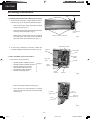
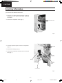
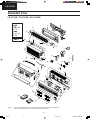
Servicing Information
Release hooks
Inspection points for the Indoor Electronic Controller
●
Tabs
Tab
1. The Electronic Controller, a signal Receiver and an
Indicator (Fig. 2) can be seen by the below steps:
–
Remove the front grille by releasing the 2 hooks
at the top of the front grille. (Fig. 1)
–
➞
Remove the 2 caps and 2 screws at the bottom
of the front grille. (Fig. 1)
➞
–
Tabs
Control Board
Cover
Remove the control board cover by releasing
the 2 tabs at left, 1 tab on top and 2 more tabs at
right side of the control board cover. (Fig. 1)
Remove 2 caps and 2 screws
Fig. 1
Electronic Controller
2. To remove the Electronic Controller, release the
hook that holding the electronic controller. (Fig. 2)
Intake Air
Sensor
CN-C (GRN)
Hook
CN-FM
(GRN)
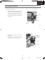
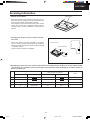
Indoor Fan Motor removal procedure :-
●
Earth Wire
Screw
1. Remove the control board by:–
–
–
–
–
–
Releasing CN-C (GRN) connector
Releasing CN-FM (GRN) connector
Releasing CN-STM connector
Remove the earth wire screw
Release the intake air sensor
Release the piping sensor
}
(Fig. 2)
–
Then remove the control board by pressing
down the hook at the left and press up the right
hook. (Fig. 3)
Signal
Receiver
Indicator
Fig. 2
Left hook
(press down)
➞
Remove the right and left screws.(Fig. 3)
Piping
Sensor
➞
–
CN-STM
Screw
(remove)
Screw
(remove)
right hook
(press up)
Fig. 3
– 33 –
Untitled-4
33
6/28/00, 4:22 PM
MAC9512086C2
CS-C73KE
Servicing Information
2. Remove the Fan Motor by :–
Release the fan motor leadwire by pressing the
hook at the center of the connector. (Fig. 4)
–
Then remove the particular piece that holding
the fan motor by pressing the tab. (Fig. 4)
–
Fan motor connector
Particular
piece
Remove the discharge grille and then the drain
hose. (Fig. 4)
Tab
Fan motor
Discharge
grille
Fig. 4
–
Finally remove the fan motor by removing the
screw. (Fig. 5)
–
REMINDER - To reinstall the fan motor, adjust
the connector of the fan motor as Figure 5.
To install back the
Fan motor,
Please adjust the
connector location.
Screw
Fan motor
Fig. 5
– 34 –
Untitled-4
34
6/28/00, 4:22 PM
MAC9512086C2
CS-C73KE
Servicing Information
Cross Flow Fan Removal Procedure.
●
1. Remove the control board and the fan motor by
referring to the "Indoor Fan Motor Removal
Procedure".
2. Remove the evaporator screw (Fig. 6)
Evaporator screw
Fig. 6
3. Press the particular piece to loosen the evaporator.
(Fig. 7)
Evaporator
➞
4. Remove the bearing. (Fig. 7)
5. Push up the evaporator and take out the cross flow
fan. (Fig. 7)
Push up
evaporator
Bearing
Press the
particular
piece
cross flow fan
Fig. 7
– 35 –
Untitled-4
35
6/28/00, 4:22 PM
MAC9512086C2
CS-C73KE
Servicing Information
• Remote Control Reset
Reset terminal
When the batteries are inserted for the first time, or
the batteries are replaced, all the indications will
blink and the remote control might not work.
If this happens, remove the back cover of the remote
control and you will find a resetting terminal, and by
shorting it with a minus screwdriver, it will return to
normal.
RES
ET
• Changing the wireless remote control transmission code
When two indoor units are installed in the same
room, in order to prevent operating errors caused by
using two remote controls, set up the remote control [B
↔ A] switch (SW1).
The unit is set to A when it is shipped.
Remote Control
SW1
B
B
Remote Controller
A
A
B
A
Switch
●
By adding a jumper wire to the remote control side and a carbon resistor (1/4 W, 10 kΩ) to the indoor printed
circuit board, it is possible to select from 4 types of transmission codes including the condition at time of
delivery condition (1).
Remote control
Indoor printed circuit board
Note
Switch SW B ↔ A
J–B
Switch SW1
RX
At product delivery
1
A
A
2
B
B
3
A
Jumper wire
A
10kΩ
4
B
Jumper wire
B
10kΩ
– 36 –
Untitled-4
36
6/28/00, 4:22 PM
MAC9512086C2
CS-C73KE
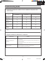
Troubleshooting Guide
Refrigeration cycle system
Normal Pressure and Outlet Air Temperature (Standard)
In order to diagnose malfunctions, make sure that
there are no electrical problems before inspecting the refrigeration cycle. Such problems include
insufficient insulation, problem with the power source,
malfunction of a compressor and a fan.
The normal outlet air temperature and pressure
of the refrigeration cycle depends on various conditions, the standard values for them are shown in the
table to the right.
Cooling mode
Gas pressure
MPa
(kg/cm2G)
Outlet air
temperature
(°C)
0.4 ~ 0.6 (4 ~ 6)
12 ~ 16
★ Condition: Indoor fan speed; High
Outdoor temperature 35°C
Difference in the intake
and outlet
air temperatures
●
Normal
More than 8°C
(15 minutes after an
operation is started.)
Measuring the air temperature
difference
Less than 8°C at the cooling mode
Value of electric
current during operation
Higher than specified
Dusty condenser
preventing heat radiation
Measuring electric current
during operation
●
Excessive amount
of refrigerant
Lower than specified
Cooling Mode
Gas side
pressure
High
Inefficient compressor
●
Measuring gas side pressure
Low
Insufficient refrigerant
Low
Clogged strainer or
capillary tube
– 37 –
Untitled-8
37
6/28/00, 5:19 PM
MAC9512086C2
CS-C73KE
Troubleshooting Guide
1. Relationship between the condition of the air conditioner and pressure and
electric current
Cooling Mode
●
Condition of the air
conditioner
Low Pressure
High Pressure
Electric current during operation
Insufficient refrigerant
(gas leakage)
V
V
V
Clogged capillary tube
or Strainer
V
V
V
Short circuit in the
indoor unit
V
V
V
Heat radiation deficiency of the outdoor
unit
B
B
B
Inefficient
compression
B
V
V
Carry out the measurements of pressure, electric current, and temperature fifteen minutes after an operation is
started.
2. Diagnosis methods of a malfunction of a compressor
Nature of fault
Insufficient compressing of a
compressor
Symptom
●
Electric current during operation becomes approximately 20% lower than the
normal value.
●
The discharge tube of the compressor becomes abnormally hot (normally 70 to 90°C).
●
The difference between high pressure and low pressure becomes
almost zero.
●
Electric current reaches a high level abnormally, and the value exceeds the
limit of an ammeter. In some cases, a breaker turns off.
●
The compressor has a humming sound.
Locked compressor
– 38 –
Untitled-8
38
6/28/00, 5:19 PM
MAC9512086C2
CS-C73KE
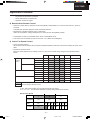
Technical Data
L Thermostat characteristics
CS-C73KE / CS-C93KE / CS-C123KE
• Soft Dry
• Cooling
(°C)
34
(°C)
34
32
32
30
30
/
COMP. ON
/
COMP. OFF = Set Temperature
/
Diff. 1.5°C
24
22
24
18
18
20
22
24
26
28
/
/
Soft Dry OFF, Soft Dry ON
Diff. 1.5°C
/
Diff. 1.0°C
22
20
16 18
Cooling OFF = Set Temperature,
/
26
20
16
/
/
Intake Air Temperature
/
/
Intake Air Temperature
26
Cooling ON
28
/
28
16
30 (°C)
16
18
20
22
24
26
28
30
Thermostat Setting (Remote Control)
Thermostat Setting (Remote Control)
L Operation characteristics
CS-C73KE / CU-C73KE
Cooling Characteristic
•
230V
220V
Piping Length Characteristic
230V
220V
30
32
34
36
38
40
42
Q:
O: Outlet
Cooling Capacity (kW)
2.0
1.8
3.5
3.0
2.5
2.0
LP:
3.0
2.5
2.0
2.2
0.65
0.60
0.55
Current (A)
3.5
LP:
Current (A)
I:
0.65
0.60
0.55
I:
O: Outlet
1.8
Air Temperature (°C)
2.0
Gas Side Piping Pressure (MPa)
Q:
2.2
-
Cooling Capacity (kW)
15
14
13
12
5
Gas Side Piping Pressure (MPa)
16
15
14
13
12
16
Air Temperature (°C)
-
•
10
PIPING LENGTH (m)
44
[Condition] Room temperature: 27/19°C
Outdoor temperature: 35/34°C
Cooling opeartion: At High fan
OUTDOOR ROOM TEMPERATURE (°C)
[Condition] Room temperature: 27/19°C
Cooling operation: At High fan
Piping length: 7.5 m
– 39 –
Untitled-8
39
6/28/00, 5:19 PM
MAC9512086C2
CS-C73KE
Technical Data
L Operation characteristics
CS-C93KE / CU-C93KE
•
Cooling Characteristic
•
Piping Length Characteristic
230V
220V
0.60
0.55
4.0
3.5
3.0
2.5
LP:
Current (A)
I:
0.50
30
32
34
36
38
40
42
O: Outlet
0.60
0.55
0.50
4.0
3.5
3.0
2.5
0
44
OUTDOOR ROOM TEMPERATURE (°C)
5
Air Temperature (°C)
2.6
2.4
I:
2.4
2.8
Gas Side Piping Pressure (MPa)
Q:
2.6
3.0
LP:
2.8
Current (A)
O: Outlet
3.0
Cooling Capacity (kW)
15
14
13
Air Temperature (°C)
16
15
14
13
Gas Side Piping Pressure (MPa)
Q:
16
-
Cooling Capacity (kW)
-
230V
220V
10
PIPING LENGTH (m)
[Condition] Room temperature: 27/19°C
Cooling operation: At High fan
Piping length: 7.5 m
[Condition] Room temperature: 27/19°C
Outdoor temperature: 35/34°C
Cooling opeartion: At High fan
CS-C123KE / CU-C123KE
• Cooling Characteristic
• Piping Length Characteristic
230V
220V
-
230V
220V
6.0
5.5
5.0
LP:
Current (A)
I:
0.45
4.5
30
32
34
36
38
40
42
O: Outlet
3.4
0.50
0.45
0.40
6.0
5.5
5.0
4.5
0
44
5
10
Air Temperature (°C)
3.6
LP:
0.55
0.50
3.8
3.2
I:
-
3.2
14
13
12
Gas Side Piping Pressure (MPa)
Q:
3.4
Cooling Capacity (kW)
3.6
Current (A)
O: Outlet
3.8
Air Temperature (°C)
15
Gas Side Piping Pressure (MPa)
Q:
Cooling Capacity (kW)
15
14
13
12
15
PIPING LENGTH (m)
OUTDOOR ROOM TEMPERATURE (°C)
[Condition] Room temperature: 27/19°C
Outdoor temperature: 35/34°C
Cooling opeartion: At High fan
[Condition] Room temperature: 27/19°C
Cooling operation: At High fan
Piping length: 7.5 m
– 40 –
Untitled-8
40
6/28/00, 5:19 PM
MAC9512086C2
CS-C73KE
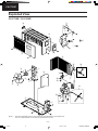
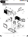
Exploded View
CS-C73KE / CS-C93KE / CS-C123KE
5
4
6
1
6
5
"
7
#
2
8
7
3
4
\
:
3
9
.
!
[
=
;
<
/
>
@
?
$
%
_
& (
,
&
+
~
%
1
(
)
}
2
{
V
}
V
1
8
2
0
]
9
^
9
|
(Note) : The above exploded view is for the purpose of parts disassembly and replacement.
The non-numbered parts are not kept as standard service parts.
CS-C73KE
– 41 –
Untitled-8
41
6/28/00, 5:20 PM
MAC9512086C2
CS-C73KE
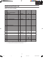
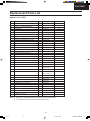
Replacement Parts List
<Model: CS-C73KE / CS-C93KE / CS-C123KE>
QTY
1
CS-C73KE
CWD50C338
4
PARTICULAR PIECE
FAN MOTOR
LEAD WIRE - FAN MOTOR
1
1
1
CWD931019
CWA92288
CWA67C2097
5
CROSS FLOW FAN
1
CWH02C060
6
8
BEARING
SCREW - CROSS FLOW FAN
EVAPORATOR & TUBE ASS'Y COMPLETE
1
1
1
CWH64K007
CWH4580304
CWB30C249
9
INTAKE AIR SENSOR HOLDER
1
CWH32142
10
ANTI VIBRATION BUSHING
FLARE NUT (1/4")
1
–
1
CWH6002140 (1/4")
FLARE NUT (1/2") OR (3/8")
DISCHARGE GRILLE COMPLETE
VERTICAL VANE WITH TAB
VERTICAL VANE
1
1
2
10
CWT25005 (3/8")
CWE20C610
CWE24458
CWE24457
NO.
1
2
3
7
11
12
13
14
15
DESCRIPTION & NAME
CHASSY COMPLETE
16
CONNECTING BAR
2
CWE26194
17
AIR SWING MOTOR
LEAD WIRE - AIR SWING MOTOR
CAP FOR DRAIN TRAY
1
1
1
CWA98260
CWA67C2106
CWH52C003
HORIZONTAL VANE
CONTROL BOARD
1
1
CWE24462
CWH10965
POWER SUPPLY CORD
SLIDE SWITCH
1
1
CWA20C751
CWA04088
ELECTRONIC CONTROLLER
RECEIVER
1
1
CWA741351
CWA74919
INDICATOR COMPLETE
LEAD WIRE - INDICATOR
TERMINAL BOARD
1
1
1
CWA741376
CWA67C2105
CWA28C577
30
INDICATOR HOLDER
TEMPERATURE SENSOR
1
1
CWD931018
CWA50C608
31
CONTROL BOARD FRONT COVER
1
CWH13456
32
CONTROL BOARD TOP COVER
REMOTE CONTROL COMPLETE
REMOTE CONTROL HOLDER
FRONT GRILLE COMPLETE
1
1
1
1
CWH13457
CWA75C724
CWH36161
CWE11C978
INTAKE GRILLE COMPLETE
DECORATION BASE COMPLETE
1
1
CWE22C333
CWE35C023
TAB
AIR FILTER
2
2
CWD931020
CWD00240
GRILLE DOOR
SCREW FOR FRONT GRILLE
1
2
CWE14236
XTN4+16C
CAP FOR FRONT GRILLE
DRAIN HOSE
2
1
CWH52267
CWH5880580
1
CWF561591
44a
OPERATING INSTRUCTIONS
(ENG/SPA/GER/FRA/NED/ITA)
OPERATING INSTRUCTIONS (POR/GRK)
OPERATING INSTRUCTIONS (RUSSIAN)
1
1
CWF561591A
44b
45
INSTALLATION INSTRUCTIONS
INSTALLATION PLATE
1
CWF61668
CWH36157
18
19
20
21
22
23
24
25
26
27
28
29
33
34
35
36
37
38
39
40
41
42
43
44
46
47
48
49
BAG COMPLETE - INSTALLATION SCREW
AIR PURIFYING FILTER COMPLETE
AIR PURIFYING FILTER
(Note)
●
●
1
1
1
2
CS-C93KE
CS-C123KE
@
@
@
@
CWA92289
CWA92290
@
@
@
@
@
@
@
@
CWB30C278
@
CWH50211
@
@
@
@
@
@
@
@
@
@
@
@
@
@
@
@
@
@
@
@
@
@
@
@
@
@
@
@
@
@
@
@
@
@
@
@
@
@
@
@
@
CWF561591B
CWH82C144
CWD00C111
CWD00220
CWB30C260
@
@
@
CWT25007 (1/2")
CWE20C624
@
@
@
@
@
@
@
@
@
@
@
@
@
@
CWA28C578
@
@
@
@
@
@
@
@
@
@
@
@
@
@
@
@
@
@
CWF61684
@
@
@
@
All parts are supplied from MACC, Malaysia (Vendor Code: 086).
t marked parts are recommended to be kept in stock.
– 42 –
Untitled-8
42
6/28/00, 5:20 PM
MAC9512086C2
CS-C73KE
Exploded View
CU-C73KE / CU-C93KE
/
[
:
>
;
=
.
<
@
?
"
&
5
4
%
2
(
,
+
~
)
3
7
\
6
$
!
8
1
#
9
(Note) : The above exploded view is for the purpose of parts disassembly and replacement.
The non-numbered parts are not kept as standard service parts.
– 43 –
Untitled-8
43
6/28/00, 5:20 PM
MAC9512086C2
CS-C73KE
Replacement Parts List
<Model: CU-C73KE / CU-C93KE
NO.
DESCRIPTION & NAME
Q’TY
CU-C73KE
CU-C93KE
REMARKS
CHASSY ASS’Y
1
CWD50K525B
@
2
FAN MOTOR BRACKET
1
CWD54113
@
3
SCREW – FAN MOTOR BRACKET
4
CWH4580399
@
4
FAN MOTOR
1
CWA95238
@
5
SCREW – FAN MOTOR MOUNT
3
CWH55027
@
6
PROPELLER FAN
1
CWH00K040
@
7
NUT – PROPELLER FAN
1
CWH56032
8
COMPRESSOR
1
2RS110D5CA04
9
ANTI – VIBRATION BUSHING
3
CWH50077
10
NUT – COMPRESSOR MOUNT
3
CWH56000
11
CONDENSER
1
CWB32C323
12
HOLDER COUPLING ASS‘Y
1
CWH35K017A
@
13
3-WAY VALVE
1
CWB01438
@
t
14
2-WAY VALVE
1
CWB02277
@
t
15
TUBE ASS’Y (STRAINER CAPILLARY)
1
CWT01C589
16
SOUND PROOF BOARD
1
CWH15266
17
OVERLOAD PROTECTOR
1
CWA67C2069
18
HOLDER – O.L.P.
1
CWH7041200
19
TERMINAL COVER
1
CWH17006
@
@
20
NUT – TERMINAL COVER
1
CWH7080300
@
21
CONTROL BOARD
1
CWH10881
@
22
TERMINAL BOARD ASS’Y
1
CWA28K217
@
23
CAPACITOR – COMPRESSOR
1
CWA31645
1
(20 µF, 370 V)
t
@
2PS146D5BA04
t
@
@
CWB32C119
CWT01C590
@
CWA67C2070
CWA31647
t
t
(30 µF, 370 V)
t
24
HOLDER CAPACITOR
1
CWH30057
@
25
CAPACITOR – FAN MOTOR
1
CWA31342
@
26
FUSE HOLDER
1
XCSCW011
@
t
27
FUSE
1
XBA2C31TR0
t
28
CABINET ASS’Y
1
CWE00K330A
@
@
29
CABINET FRONT PLATE
1
CWE06C117A
@
30
CONTROL BOARD COVER
1
CWH13302
31
HANDLE
1
CWE16037C
@
@
32
STRAINER
1
CWB11025
@
(Note)
●
●
(1.2 µF, 400 V)
All parts are supplied from MACC, Malaysia (Vendor Code: 086).
t marked parts are recommended to be kept in stock.
– 44 –
Untitled-8
44
6/28/00, 5:20 PM
MAC9512086C2
CS-C73KE
Exploded View
CU-C123KE
^
<
|
\
.
/
[
:
>
;
(
=
]
_
9
{
5
4
2
!
-
3
@
?
#
,
+
~
%
$
&
6
)
8
1
7
"
(Note) : The above exploded view is for the purpose of parts disassembly and replacement.
The non-numbered parts are not kept as standard service parts.
– 45 –
Untitled-8
45
6/28/00, 5:20 PM
MAC9512086C2
CS-C73KE
Replacement Parts List
<Model: CU-C123KE
NO.
1
DESCRIPTION & NAME
Q’TY
CU-C123KE
REMARKS
CHASSY ASS’Y
1
CWD50K658A
2
FAN MOTOR BRACKET
1
CWD54254
3
SCREW – FAN MOTOR BRACKET
6
CWH55413
4
FAN MOTOR
1
CWA95378
5
SCREW – FAN MOTOR MOUNT
4
CWH55252
6
COMPRESSOR
1
2KS224D5CA02
7
ANTI – VIBRATION BUSHING
3
CWH50055
8
NUT – COMPRESSOR MOUNT
3
CWH4582065
9
CONDENSER
1
CWB32C334
10
TUBE ASS'Y (STRAINER CAPILLARY)
1
CWT01C647
11
HOLDER COUPLING ASS'Y
1
CWH35K062
12
2-WAY VALVE
1
CWB02514
t
13
3-WAY VALVE
1
CWB01480
t
14
SOUND PROOF BOARD
1
CWH15288
15
SOUND PROOF MATERIAL
1
CWG30911
16
WIRE NET
1
CWD04197A
17
AIR GUIDER PROPELLER FAN
1
CWD31138
18
OVERLOAD PROTECTOR
1
CWA67C2166
19
HOLDER – O.L.P.
1
CWH7041200
20
TERMINAL COVER
1
CWH17006
21
NUT – TERMINAL COVER
1
CWH7080300
22
CONTROL BOARD
1
CWH10972
23
TERMINAL BOARD ASS'Y
1
CWA28K217
24
CAPACITOR – COMPRESSOR
1
CWA31647
25
HOLDER CAPACITOR
1
26
CAPACITOR – FAN MOTOR
1
27
FUSE HOLDER
1
XCSCW011
28
FUSE
1
XBA2C31TR0
29
PROPELLER FAN ASS'Y
1
CWH00K087
30
NUT – PROPELLER FAN
1
CWH56053
31
CABINET SIDE PLATE (RIGHT)
1
CWE04217A
32
CABINET SIDE PLATE (LEFT)
1
CWE04220A
33
CABINET FRONT PLATE
1
CWE06K104A
34
HANDLE
1
CWE16037C
35
CONTROL BOARD COVER
1
CWH13461
1
CWD91258
1
CWE03111A
PLATE FOR C.B. COVER
36
37
(Note)
CABINET TOP PLATE
●
●
t
t
t
t
(30 µF, 370 V)
CWH30057
CWA31227
t
(1.5 µF, 400 V)
t
All parts are supplied from MACC, Malaysia (Vendor Code: 086).
t marked parts are recommended to be kept in stock.
– 46 –
Untitled-8
46
6/28/00, 5:20 PM
MAC9512086C2
CS-C73KE
Electronic Parts List
<Model: CWA741351
DESCRIPTION & NAME
SYMBOL
SH CAPACITOR
A31698
DB1
DIODE
A54CS1VB20E
FUSE
FUSE
XBA2C31TR0
C–FM
IC4
IC5
INTEGRATED CIRCUIT
A52C040
INTEGRATED CIRCUIT
A52C094
RY–Hi, RY–M, RY–SHi
ELECTRO MAGNETIC RELAY
A00160
RY–PWR
ELECTRO MAGNETIC RELAY
A00106
SSR 1
SW2, SW3
TYRISTOR
PUSH SWITCH
A56W2DEH1–5
A01059
TRANSFORMER
A40366
T1
(Note)
PART NO.
●
TEMP FUSE
FUSE
ZNR1, ZNR2
DIODE
A16C204
ERZVEAV511
All parts are supplied from MACC, Malaysia (Vendor Code: 086).
MACC
Printed in Malaysia
P990103000CT
– 47 –
Untitled-8
47
6/28/00, 5:20 PM
MAC9512086C2
CS-C73K/C93K/C1233K
CS-C73K/C93K/C123K
CS-C73K/C93K/C123K
CS-C73K/C93K/C123K
ELECTRONIC CIRCUIT DIAGRAM
• CS-C73KE / CU-C73KE
• CS-C93KE / CU-C93KE
• CS-C123KE / CU-C123KE
5 GND
FO 4
4.7k
c
b
R21
6.2k
e
4.7k
TEST
R9
10k
R8
1k
e
Q7
A55DC143XKTX
10k
1 2
CN-FUSE1
AC
(WHT)
e
Q6
A55DC143XKTX
21 P53
28
RX1
SW1
R30
24k
R32
102k
R27 +
20k –
(PH4)
CN-TH
C16
10µ
16V
R26 +
15k –
9
g
11
f
12
e
13
BZ1
d
14
BZ
c
15
R23
1k
(MX-5)
CN-STM
AIR SWING
MOTOR
b
16
a
7
P30
P31/T01
P33/TI1
P32/T01
P34/TI2
SSR
RY-H
BUZZER
RY-M
RY-SHI
AUTO RESTART
GROUND
P56
P20/SI1
AVref
POWER
57
R24
10k
+
–
C2
470µ
25V
(NHG)
5V
O
AN17 54
PUMP DOWN
ANI6 53
REMOTE-CONTROL
COMMAND INPUT
+
G
–
C3
100µ
16V
(NHG)
D1 5
34
P66
8 MHz
OSC
RESET
35
36
37
38
39
40
ANI4 51
INTAKE AIR TRMP
ANI3 50
ANI2
41
42
43
44
45
46
47
49
10
20
30
40
50
60
70
Temperature (°C)
-10
0
10
20
30
40
50
Temperature (°C)
RED
BLUE
OLP Characteristics
(Compressor)
CAPACITOR
RY-M
FAN MOTOR
JX1
Q1
DC114EKTX
–
C18
10µ
16V
C19
0.01µ
C5
0.022µ
R2
10k
POWER CLOCK c
GENERATOR
120
CR1
0.022µ
120
CR2
0.022µ
CS-C73K ( CWA 12343 )
4.7k
FUSE
3.15A
e
PIPE TEMP
Indoor Heat Exchanger
Temp. Data
0
Fig. 3
R5
10k
R4
100k
ANI5 52
TIMER SHORTEN
20
BLUE
ZNR1
511U
POWER CLOCK INPUT
P63
1
RY-H
10k
P61
2
30
COMPRESSOR
b
AUTO OPERATION
3
RY-SHI
C4
0.1µ
56
AVdd 55
P60
2
Intake Air
Temp. Data
YELLOW
DISPLAY
P57
Q2
2SC2412KTX
R3
1.0k
+
Fig.2
–
C5
1µ
50V
c
ZD1
7.5EL1
Q3
2SC2412KTX
RESET SIGNAL
GENERATION
RESET SIGNAL
c GENERATION
b
BLUE
BLUE
CR3
120
0.022µ
RED
5
CAPACITOR
3
R6
12k
CR4
120
0.022µ
R10
13k
1
b
e
48
Fig.2
e
R7
6.2k
0.7
C7
0.01µ
0.5
0.3
R28
10k
C-FM
1.5µ
400V AC
CN-C
(VH-3)
(GREEN)
L1
A438LM31A02T
10
B
Vss
33
C15
10µ
16V
1
2
3
4
I
+
G
1
40
0
5
R41
10k
IC5
A52A2003GR2
STEPPING MOTOR DRIVE
C23
0.01µ
6
+
–
1 2 3
RED
JX2
C1
3300µ
35V
(NHG)
–
O
12
R1
5.1k
D6 6
4 SK
12V
4
YELLOW
A56W2DEH1-5
P21/SO1 58
P64 STEPPING
MOTOR
P65 DRIVE
32
SIGNAL
R29
24k
RS 8
GND 7
IC4
78A05
REGULATOR
BLUE
C
C17
0.01µ
1 R/B
2 Vcc
3 CS
P22/SCK1 59
31
R31
26.1k
C14
0.1µ
~
IC5
78N12H
REGULATOR
I
+
IC2
A52BR9020F
NC 63
P23 60
29 P62
30
6
ANI1
27
3
NC 62
P55
DB1
S1VD20
~
+
10
–
NC 64
DISPLAY
T1
5
P24 61
ANI0
26
R35
330
1
RELAY DRIVE
SIGNAL
AVss
24
R37
330
1
2
3
4
5
2
NC
R36
330
REMOTE CONTROL NO.
SW1
RX1
1
OFF
2
ON
3
OFF
SHORT
4
ON
SHORT
PIPE TEMP. SENSOR
(20k 3950)
3
NC
23
25
Fig.1
4
22 NC
RED
AIR TEMP. SENSOR
(15k 3950)
5
IC
ORG
RELAY DRIVE
SIGNAL
X1
ORG
P52
6
P35/PCL
P36/BUZ
Vss
7
P37
P40
P41
P42
P43
P44
8
X2
OFF/ON
9
Vdd
D
10
P03/INTP3
6
5
4
3
2
1
R38
330
P51
P02/INTP2
(PH-6)
CN-DISP
20
P01/INTP1
ORG
19
1
2
3
4
5
6
7
8
9
NC
SLEEP
11
RY-PWR
(MX-9)
CN-DISP
GRN
A54LNK3171B
TIMER
12
18 P50
R39
330
RESET
POWERFUL
13
17 P47
A54LNK2172B
ECONOMY
P45
P46
INDICATOR
P67
E
ZNR2
511U
14
Pipe Temp. Sensor
Intake Air Temp. Sensor
10
IC1
A52D0001G502
15
OVER LOAD
PROTECTOR
FUSE
3.15A
RY-M
RY-H
RY-SHI
SSR1
RELAY DRIVE
16
1 2
RY-PWR
RELAY DRIVE
2
50
10k
CN-FUSE2
1
Voltage (V)
R22
2.2k
b
D1
ERA15-01
–
137k
RY-PWR
C19
0.01µ
6.3V
47µ
+
0.01µ
Intake Air/ Indoor Heat
Exchanger Temp.
GRY
b
Resistance (k )
VCC2 3
0.01µ
Q4
2SD148-4X
c
SSR1
OUT 2
6 CO
Senser (Thermistor)
Characteristics
60
1
2
113°C
THERMAL
FUSE
102°C
THERMAL
FUSE
c
RY-PWR DRIVE
R34
150k
20
1
2
3
4
5
6
7
YELLOW
7 IN-
R16
5.1k
BROWN
F
R17
1k
1
2
3
VCC1 1
ORANGE
8 IN+
1
2
AC 220-230V
50/60Hz
(MX-3)
CN-RCV1
330
Fig. 2
MAIN SWITCH
RECEIVER
PH302C
Fig. 1
70
MAIN
WHITE
G
40
60
80
100
120
140
CN-FM
(VH-1)
(GREEN)
C22
10µ
16V
5
4
X1
8MHz (27pF X 2)
3
CS-C93K ( CWA 12344 )
2
1
CS-C123K ( CWA 12352 )
FAN
MOTOR
8
1
2
3
4
5
(GND)
R13
10k
CHECK PIN
C8
0.01µ
10
R12
10k
1
5
SW3
AUTO
C10
0.01µ
2
7
(ZH5)
R15
10k
5
3
SW2
PUMP DOWN
0.7
R14
2k
0.5
3
0.3
A
20
2
1
ECD
1
3
4
5
6
7
8
9
10
11
6/21/00, 10:51 AM
12
13
14
40
60
15
80
100
120
16
20
140
17
40
60
80
18
100
120
140
19
CS-C73K/C93K/C123K
How to use electronic circuit diagram
ELECTRONIC CIRCUIT DIAGRAM
C1
47µ
R11
510k
R03
x2
+ C2
– 47µ
+
C9
0.01µ
–
R9
200k
R5
2.2
1/8W
R3
51
Q2
2SD602
0 sec.
60 sec.
0 sec.
Time Save Control
7 min.
42 sec.
Anti-Freezing Control
4 min.
0 sec.
Mode Jugdement
20 sec.
0 sec.
Off
6 min.
36 sec.
On
10 min.
40 sec
60 sec.
4 sec.
Cooling
70 sec.
7 sec.
20 sec.
2 sec.
180 sec.
18 sec.
40 sec.
4 sec.
Deodorizing Control
Comp. Reverse Rotation Detection
Comp./Fan motor Delay Timer
360 sec.
36 sec.
5 min.
30 sec.
2 min.
0 sec.
1.6 sec.
0 sec.
SLo Timer
Intake Air Anti-Freezing Prevention
8 sec.
8 sec.
16 min.
96 sec.
POWERFUL MODE
15 min.
15 sec.
5 sec.
5 sec.
0 ~ 150 sec.
0 sec
Random FM Timer (ECONOMY Mode)
Random Auto Restart Control
2
1
ECD
2
3
8
7
6
5
4
3
2
1
COM1
COM2
SEG0
SEG1
SEG2
SEG3
SEG4
SEG5
SEG6
17 XOSC2
SEG 7 64
SEG8 63
R6
300
C6
0.1µ
SEG9 62
19 VSS
DOOR OPEN/CLOSE
SW1
(CLOSE:ON)
SW2
20 RESET
SEG10 61
21 PC3
SEG11 60
22 PC2
SEG12 59
SEG13 58
23 PC1
R12
51k
IC1
24 PC0
Remote Controller No.
Remarks
R13
51k
R14
51k
SEG15 56
26 PA1
SEG16 55
27 PA2
SEG17 54
28 PA3
SEG18 53
29 PA4
SEG19 52
30 PA5
SEG20 51
31 PA6
SEG21 50
SEG27
SEG26
SEG25
SEG24
32 PA7
33
34
35
36
37
38
39
40
41
42
43
44
45
46
47
(POWERFUL)
SOFT DRY: 10 min. operation
FAN SPEED
(TEMP )
SEG14 57
25 PA0
SEG28
1 sec.
2 min. 58 sec.
Soft Dry
A
1 min.
9
SEG22 49
SEG 23
48
SELF
DIAGNOSIS
SLEEP
TIMER
ON
TIMER
CANCEL
AIR SWING
AUTO
TIMER
OFF
TIMER
SET
SW2
0
ECONOMY
AIR SWING
MANUAL
(OFF / ON)
aI
LIQUID CRYSTAL DISPLAY
R1
100k
10 sec.
Forced Operation
Soft Dry
B
1 min.
10 min.
Time Delay Safety Control
C
1 hr.
10
SEG29
Real Timer
48 sec.
11
18 XOSC1
6 sec.
8 hrs.
12
SEG30
Sleep Mode Operation
13
SEG31
1 hr.
14
SEG32
Sleep Mode Waiting
15
COM0
X2
32.768kHz
16
VLCD3
C5
8P
(NPO)
Test mode
test point
( When
Short-circuited )
R7
200k
X1
3.52Hz
(33P x 2)
R4
22k
J-B
Time
R8
200k
R2
1.5k
VLCD2
* Diode without indication .............. MA165
* Circuit Diagram is subject to change without
notice for further development.
TIMER TABLE
Name
BOTTOM VIEW
C4
8P
(NPO)
RESET
D
TOP VIEW
CN1
RMO
* Indications for resistance
a. K .... k
M ... M
W ... watt
Not indicated .... 1/4W
b. Type
Not indicated .......... carbon resister
Tolerance±5%
.......... metal oxide resister
Tolerance±1%
PRINT PATTERN
INDOOR UNIT PRINTED CIRCUIT BOARD
C8
0.01µ
BZ
15°C
Q1
2SB710
VDD
17°C
LED1
SID1003BQ
VLCD1
16°C
CS-C73K/C93K/C123K
C7
0.01µ
PC7
E
27°C
WIRELESS REMOTE CONTROL
OSC1
Cooling
• REMOTE CONTROL
PC6
Intake air Temperature Discharge air
Pipe
temperature
setting
temperature temperature
PRINT PATTERN
INDOOR UNIT PRINTED CIRCUIT BOARD
PC5
F
* Indications for capacitor
a. Unit
µ .... µF
P .... pF
b. Type Not indicated ... ceramic capacitor
(S) .......... S series aluminium
electrolytic capacitor
(Z) .......... Z series aluminium
electrolytic capacitor
(SU) ....... SU series aluminium
electrolytic capacitor
(P) .......... P series polyester system
(SXE) ..... SXE series aluminium
electrolytic capacitor
(SRA)...... SRA series aluminium
electrolytic capacitor
(KME)......KME series aluminium
electrolytic capacitor
OSC2
Before using the circuit diagram, read the following carefully.
* Voltage measurement
Voltage has been measured with a digital
tester when the indoor fan is set at high fan
speed under the following conditions without
setting the timer.
Use them for servicing.
Voltage indication is in Red at all operations.
CS-C73K/C93K/C123K
PC4
G
CS-C73K/C93K/C123K
MODE
(TEMP )
CLOCK
J-B
OFF
1
ON
2
OFF
SHORT
3
ON
SHORT
Comp. ON 5 min. and above
4
5
6
7
8
9
10
11
6/21/00, 10:52 AM
12
13
14
15
16
17
18
19