1
HP Archive
This vintage Hewlett Packard document was preserved
and distributed by
www. hparchive.com
Please visit us on the web.
For free distribution only!
Thanks to on-line curator: Bernhard Voss for supplying
and scanning this vintage document.
OPERATING
./
INFORMATION
. 862908
RF PLUG-IN
2'.0 - 18.6 6Hz
Flin-
HEWLETT
~~ PACKARD
General Information
Model 86290B
86290B
2:
- . : : . ~
j
",
,~
~~:-.~.~:.~;-::-;:::.-~! l'!~f;~
.
130
120
140
150
100
200
300
400
500
aoo
GHz
170
20
18.0
rTfTTTTTT1TllT1
-300
-200
-100
0
... 100 ... 200
...300
-c )
!
~'~~~l _
•. _ ~
40
60
80
100
120
140
160
180
rrJ'TlllllT1TfT :< 0-186 ifiTlll11l1T1TT
o
~
~
~
~
~~
~oo
(}
SCALES FOR 8620C*
RF TEST CABLE*
EXTENDER BOARD*
*NOTE: See paragraph 1-34 for part number information
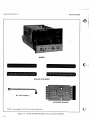
Figure 1-1. Model 86290B RF Plug-In with Accessories Supplied
. 1-0
2"
~
_
_
~"-':::,-i~"~,/4~~~
,
16.0
f1TTlTITTTTTI11120-186
o
)
____ 1 . __~
~o
~
General Information
Model 86290B
SECTION I
GENERAL INFORMATION
1-1.
INTRODUCTION
Supplied with this manu,al is an Operating
5upplement. The Supplement is a
copy of the first three sections of this manual, and
sQ-ould be kept with the instrument for use by the
operator. Additional copies of the Operating Information Supplement can be ordered through
your nearest Hewlett-Packard office. The part
number is listed on the title page.
1-4.
Infor~ation
1-2.' This Operating and Service manual contains
information required to install, operate, test, adjust, and service the Hewlett-Packard Model
86290B RF Plug-in. Figure 1-1 shows the instrument and accessories supplied. This section covers instrument identification, description, options, accessories, specifications; and other basic
information.
1,-3. This manual is divided into eight sections
which provide information as follows:
a.
SECTION I, GENERAL INFORMATION,
contains the instrument description and
specifications as well as the accessory and
recommended test equipment list.
b.
SECTION II, INSTALLATION, contains
information relative to receiving inspection,
preparation for use, mounting, packing, and
shipping.
1-5. Also listed on the title page of this manual is
a Microfiche part number. This number can be
used to order 4 x 6-inch microfilm transparencies
of the manual. Each microfiche contains up to 60
photo-duplicates of the manual pages. The microfiche package also includes the latest Manual
Changes supplement as well as all pertinent Service Notes.
1-6. SPECIFICATIONS
c.
SECTION III, OPERATION, contains
operating instructions for the instrument.
d.
SECTION IV, PERFORMANCE TESTS,
contains information required to verify that
instrument performance is in accordance
with published specifications.
e.
SECTION V, ADJUSTMENTS, contains information required to properly adjust and
align the instrument after repair.
f.
SECTION VI, REPLACEABLE PARTS,
contains information required to order all
parts and assemblies.
g.
SECTION VII, MANUAL CHANGES,
contains backdating information to make this
manual compatible with earlier equipment
configurations.
1-7. Instrument specificaions are listed in Table
1-1. These specifications are the performance stan-
dards or limits against whch the instrument is
tested. Table 1-2 lists supplemental characteristics.
Supplemental characteristics are not specifications
but are typical characteristics included as additional information for the user.
1-8. SAFETY CONSIDERATIONS
1-9. General
1-10. Before operating this instrument, you
should familiarize yourself with the safety markings on the instrument and safety instructions in
this manual. This instrument has been manufactured and tested according to international safety
standards.
1-11.
h.
SECTION VIII, SERVICE, contains decriptions of the circuits, schematic diagrams,
parts location diagrams, and troubleshooting
procedures to aid the user in maintaining the
instrument.
;1\
ill
f
l..
Safety Symbols
Instruction manual symbol: the apparatus
will be marked with this symbol when it is
necessary for the user to refer to the instruction manual in order to protect the apparatus against damage.
Indicates dangerous voltages.
Earth Terminal.
1-1
General Information
I WARNING
.~
I
Mode186290B
The WARNING sign denotes a
hazard. It calls attention to a procedure, practice, or the like, which,
if not correctly performed or adhered to, could result in injury or
loss of life. Do not proceed beyon'd
a WARNING sign until the indicated conditions are fully understood
and met.
The CAUTION sign denotes a hazard. It calls attention to an operating procedure, practice, or the like,
which, if not correctly. performed
or adhered to, could result in
damage fo or destruction of part
or all of the equipment. Do not
proceed beyond a CAUTION sign
until the indicated conditions are
fully understood and met.
ment should 'be made inoperative and
secured against any unintended operation.
I
I'
WARNING
BEFORE SWITCHING THE INSTRUMENT ON, ensure that all ac line powered devices connected to the instrument are connected to the protective earth ground.
~
BEFORE APPLYING POWER, make
sure the mainframe ac Input is set for
the available ac line voltage, that the
correct fuse is install~, and that all
normal safety precautions have:been
taken.
1-12. Operation
1-14. Service
1-13. BEFORE APPLYING POWER, refer to
SAFETY CONSIDERATIONS in Section l.of the
Operating and Service manual for the mainframe.
1-15. The information, cautions, and warnings in
this manual must be followed to ensure safe operation and to keep the instrument safe. SERVICE
AND ADJUSTMENTS SHO'ULD BE PERFORMED ONLY BY QUALIFIED SERVICE
PERSONNEL.
The information, cautions, and warnings in this
manual must be followed to ensure safe operation
and to keep the instrument safe.
~
WARNING
I
BEFORE SWITCHING ON THE INSTRUMENT, the protective earth terminal of the mainframe must 'be connected to the protective conductor of
the (mains) power cord. The mains
plug should only be inserted in a socket outlet provided with protective
earth contact. This protection should
not be negated by using an extension
cord (power cable) without a protective grounding conductor. Grounding
one conductor of a two-conductor
outlet is not sufficient protection.
I
WARNING
~
Any interruption of the protective
(grounding) conductor, inside or outside the instrument, or disconnection
of the protective earth terminal coOld
make this instrument dangerous.
Whenever it is likely that this protection has been impaired, the instru1-2
1-16. Adjustment or repair of the opened instrument with the ac power connected should be
avoided as much as possible but, when unavoidable, should be performed only by qualified service personnel who are aware of the hazard involved.
1-17. Capacitors inside the instrument may still
be charged even though the instrument has"been
disconnected from its source of supply.
I
WARNINGI
Servicing this instrument often requires working with the instrument's protective covers removed
. and ac power connected. Extreme
caution should be exercised since
energy available at many points in
the instrument may, if contacted,
result in personal injury.
[iARNING
I
BEFORE SW4TCHING THE INSTRUMENT ON, ensure that all ac line powered devices connected to the instrument are connected to the protective earth ground.
Model 86290B
1-18.
General Information
INSTRUMENTS COVERED BY MANUAL
1-19. Attached to the instrument is a serial
number plate (Figure 1-2). The serial number is in
two parts. The first four digits and letter are the
serial number prefix; the last five digits are the
suffix. The prefix is the same for all identical instruments; it changes only when a change is made
to the instrument. The suffix, however, is assigned
sequentially and is different for each instrument"
The contents of this manual apply to instruments
with the serial number prefix(es) listed under
SERIAL NUMBERS on the title page.
SERIAL ,.,NUMBER
r
PREFIX SUFFIX
Figure 1-2"
,
Serial Number Plate
1-20" An instrument manufactured after the
printing of this manual may have a serial number
prefix that is not listed on the title page" This
'unlisted serial number prefix indicates the instrument is different from those described in .this manuaL The manual for thi ~ newer instrument is accompanied by a yellow Manual Changes supplement. This supplement contains "change information" that explains how to adapt the manual to the
newer instrument.
1-21. In addition to change information, the supplement may contain inforination for correcting
errors in the manual. To keep this manual as current and accurate as possible, Hewlett-Packard
recommends that you periodically request the
latest Manual Changes supplement" The supplement for this manual is identified with this
manual's print date and part number, both of
which appear on the manual's title page. Complimentary copies of the supplement are available
from Hewlett-Packard.
1-22. For information concerning a serial
number.prefix that is not listed on the title page or
in the Manual Changes supplement, contact yournearest Hewlett-Packard office.
1-23.
DESCRIPTION
1-24. The HP Model 86290B is designed as a
plug-in for the 8620C mainframe. The mainframe
and 86290B RF Plug-in make up a solid-state
sweep signal source with a frequency range of 2.0
- 18.6 GHz. The frequency range is swept fn
either one cCJntinuous band or in three single
bands. In single band operation, Band 1 sweeps 2.0
- 6.2 GHz, Band 2 sweeps 6.0 - 12.4 GHz, and
Band 3 sweeps 12.0 - 18.6 GHz. When Band 4 is
selected on the mainframe, the full frequency
range of 2.0 - 18.6 GHz is swept continuously.
The fundamental frequency of 2.0 - 6.2 GHz is
generated by a YIG Tuned Oscillator (YTO). A
YTO test signal (typically -10 dBm) is available at
the rear panel AUX OUT connector. A YIG Tuned
Multiplier (YTM) provides the frequency range
from 6.0 to 18.6 GHz.
1-25. The RF output of the instrument is controlled by the front panel POWER LEVEL control.
Power can be leveled, externally or internally,
across the band using a conventional power sampling and feedback technique" The automatic level
control (ALC) switch selects the mode of leveling
either internal (INT), external crystal (EXT), or
power meter (MTR). A front panel EXT INPUT
connector and ALC GAIN control are provided to
use with an external leveling loop. When the UNLEVELED light is on, it indicates that the leveling
loop is open over a portion of the swept band.
BNC connectors on the rear panel allow for external FM signal inputs, a 1 V/GHz frequency reference voltage output, and a SEQ SYNC timing
signal.
1-26. Options for the Model 86290B RF Plug~in
are available to (1) substitute a rear-panel RF
OUTPUT connector and also route the EXT INPUT connector to the rear panel and (2) provide a
front-panel or rear-panel APC-7 RF OUTPUT
connector.
1·27.
Option 004
1-28" The 86290B Option 004 has the RF OUTPUT and ALC EXT INPUT connectors mounted
on the rear panel instead of the front panel. Installation information may be obtained from the
nearest Hewlett-Packard Field Service center. Installation of the Option 004 requires the parts
listed in Table 1-3.
1-3
General Information
1-29.
Option 005
1-30. The standard 86290B RF Plug-in uses a
Type-N RF OUTPUT connector. The 86290B
Option 005 provides an APC-7 OUTPUT connector. See Table 1-3 for parts required to install
O·ption 005.
1-31.
1-33_ EQUIPMENT REQUIRED BUT NOT
SUPPLIED
1-34. To have a complete operating sweep
oscillator unit, the Model 86290B RF Plug-in must
be installed in an 8620C mainframe.
NOTE
All
86290B operation
and
maintenance procedures in this
manual are set up using the HP
"Model 8620C mainframe. The
86290B will not operate with an
8620A or 8620B mainframe.
;
1-35.
EQUIPMENT AVAILABLE
1-36.
SERVICE ACCESSORIES
1-37. A service Accessories package for the
86290B RF Plug-in is available for convenience in
aligning and trou·bleshooting the mainframe and
RF Plug-in. The Service Accessories Package as
shown in Figure 1-3, contains a plug-in extender
cable, two service boards, and an adjustment tool.
The package may be obtained from HewlettPackard by ordering HP Part Number
08620-60124.
1-38.
Reversing Extender Board
1-39. A reversing extender board (Figure 1-4) is
available for adjusting and troubleshooting when
two circuit boards are extended at the same time.
1-4
The .reversing extender board is especially convenient when two adjacent boards are extended. This
allows simultaneous access to the components of
both boards. One board is extended on the reversing extender board with a second board on the"
standard extender board (Figure 1-1). The board
may be obtained from Hewlett-Packard by orderingPart No. 86290-60033.
ACCESSORIES SUPPLIED
1-32.
Figure 1-1 shows the HP Model 86290B
RF Plug-in, the four dial scales'to be mounted in
the mainframe, the RF Test Cable (HP Part :t'~o.
86290-60032) for testing and troubleshooting
the RF Section, and an extender board (HP Part
No. 86290-60020) to extend printed-circuit boards
for troubleshooting.. The four scales supplied are
as follows: 2.0 - 6.2 GHz, HPPart No . 8629000014"; 6.0 - 12.4 GHz, HPPartNo. 86290-00015;
12.. 0 - 18.6 GHz, HP Part No. 86290-00040;
and 2.0 - 18.6 GHz, HP Part No. 86290-00041.
i
Model 8629GB
1-40.
RF Section 36-Pin Extender
1-41. A 36-pin extender is available for extending
the RF Section approximately 1 inch. This allows
easy access to components located near the front
of the instrument. This extender, shown in Figure
1-5, may be obtained from Hewlett-Packard by
ordering Part No. 08621-60056.
1-42. Model 8755B/182T Swept Amplitude
Analyzer and Oscilloscope
1-43. The Model 8620C/86290B Sweeper is compatible with the· Hewlett-Packard Model 8755B
Swept Amplitude, Analyzer. For all swept
amplitude measurements, the 27.8 kHz
squarewave modulation is applied directly to the
8620C rear-panel EXT AM connector. This eliminates the need for an external modulator,
thus providing maximum available power to a test
setup.
1-44.
Power Meters and Crystal Detectors
1-45. The Hewlett-Packard Model 432A Power
Meter may be used for external leveling of the
Model 86290B Plug-in RF Output Power. Externally leveled power is also available using an HP
8470B Crystal Detector. Section III contains
detailed instructions for using the external power
leveling systems.
1-46.
Model 8410B/8411A Network Analyzer
1-47.. The Model 8620C/86290B 'Sweeper provides multi-octave phase/gain measurement capability with the Hewlett-Packard Model 8410B Network Analyzer System.. The combination of
the Model 8410B Network Analyzer, the Model
8411A Frequency Converter, and an appropriate
display plug-in forms a phase meter and a ratio
meter for direct phase and amplitude ratio
measurement on RF voltages. These measurements
can be made on single frequencies and on swept
Model 86290B
frequencies from 2.0 to 18.0 GHz. The interfacing
between the 8410B and 8620C/86290B sweeper
permits the 8410B to phase lock over the 2.0 to
18.0 GHz range. Sweep timing pulses for the
8410B Network Analyzer are available at the rearpanel SEQ SYNC connector.
General Information
1-48.
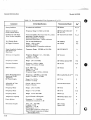
RECOMMENDED TEST EQUIPMENT
1-49. Equipment required to maintain the Model
86290B is listed in Table 1-4. Other equipment
may be substituted if it meets or exceeds the critical
specification listed in the table.
1-5
General Information
Model 86290B
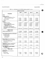
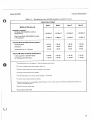
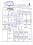
Table 1-1. Specifications for 86290B Installed in 8620C (1 of 2)
SPECIFICATIONS l
Band 1
Band 2
Band 3
Band 4
FREQUENCY
Range:
2.0 - 6.2 GHz
6.0 -12.4 GHz
1~.0
- 18.6 GHz 2.0 - 18.6 GHz
Accuracy (at 25° C):2
CW Mode 3 (or Sweep Time> 0.1 sec
with FM switch in PL or FM):
±20 MHz
±20 MHz
±20 MHz
All Sweep Modes:
±30 MHz
±30MHz
±30MHz
±80MHz
Marker:
±30MHz
±30 MHz
±30MHz
±80MHz
Temperature Change:
±0.5 MHzjOC
±1.0 MHzjOC
±1.5 MHzjOC
±2.0 MHz/oC
10% Line Voltage Change:
10 dB Power Change from Specified
Maximum Power:
3:1 Load SWR, all phases:
Residual FM (in 10 kHz bandwidth;
FM-NORM-PL switch in NORM position):
CWMode:
±100 kHz
±100 kHz
±100 kH2
±100 kHz
±200 kHz
±400 kHz
±600 kHz
±600 kHz
±100 kHz
±200 kHz
±300 kHz
±300 kHz
<10kHz peak
<20 kHz peak
<30 kHz peak
<30 kHz peak
±80MHz
Stability: .
POWER OUTPUT
Maximum Leveled Power (25°C):8
>+10 dBm
(10 mW)
>+10 dBm
(10 mW)
>+10 dBm
(10 mW)
>+10 dBm
(10 mW)
Power Variations (at maximum leveled pov.er):
Internally Leveled: 9
<± 0.7 dB
<± 0.7 dB
<±O.S dB
<± 0.9 dB
Externally Leveled4
Crystal Detector:
<±O.15 dB
<±O.15 dB
<±O.15 dB
<±O.15 dB
<±0.15 dB
<±0.15 dB
<±0.15 dB
<±O.15 dB
Power Meter:
5
Sp..urious Signals (below fundamental at
':\.0-
s~ecified maximum power, 2-18.6 GHz):
> 25 dB
>25dB
> 50 dB
> 25 dll
> 50 dB
> 50dB
>50dB
> 55 dB
> 55 dB
> 55 dB
> 55 dB
< 1.9:1
<1.9:1
<1.9:1
<1.9:1
±75 MHz
±75 MHz
±75 MHz
±75 MHz
± 5 MHz
± 5 MHz
± 5 MHz
± 5 MHz
Harmonically Related Signals:
> 25 dB
Nonharmonics:
Residual AM: AM noise in 100 kHz bandwidth (below fundamental at specified
maximum power):
Source SWR, 50n Nominal Impedance,
2-18GHz:
Internally Leveled:
MODULATION
External FM:
Maximum Deviations for Modulation
Frequencies:
DC to 100 Hz:
100 Hz to 2 MHz:
1-6
Model 86290B
General Information
Table 1-1. Specifications for 86290B Installed in 8620C (2 of 2)
SPECIFICATION,Sl
Band 1
Band 2
Band 3
Band 4
MODULATION (Cont'd)
Sensitivity (nominal):6
FM Mode (FM-NORM-PL switch in
FM position):
tf.!:.
-20 MHz/V
-20 MHz/V
-20 MHz/V
--:-20 MHz/V
-6 MHz/V
-6 MHz/V
-6 MHz/V
-6 MHz/V
>30 dB
>30 dB
>30 dB
>30 dB
Symmetry:
40/60
40/60
40/60
40/60
Attenuation for +5 volt Input:
30 dB
30 dB
30 dB
30 dB
1 kHz squarewave ON/OFF Ratio:
>25dB
>25 dB
>25dB
>25 dB
RF Blanking ON/OFF Ratio:
>30dB
>30 dB
> 30 dB
> 30 dB
Phase-Lock Mode (FM-NORM-PL switch
in PL position):
External AM (at specified maximum power):7
ON/OFF Ratio:
Internal AM (below maximum leveled power):
1 All
specifications are at 25 degrees C. Allow 30 min'utes warmup time.
2 See
also the Supplemental Characteristics, Table 1-2.
3 Approach
desired frequency from low-frequency end of band.
4Excluding coupler and detector variation.
5 Use HP
Model 432A power meter. Sweep duration> 10 seconds.
~A positive input voltage decreases frequency.
requirements for compatibility with HP 8755A, ±6V, 27.8 kHz square wave MODULATOR DRIVE a~tPut connected to external AM input.
7 Specific
8Subtract 0.5 dB for Option 004.
9 Add 0.1 dB
for Option 004.
1-7
General Information
Model 86290B
Table 1-2. Supplemental Characteristics for 86290B Installed in 8620C (1 of 2)
SUPPLEMENTAL CHARACTERISTICS
NOTE: Values in this table are not specifications but are typical characteristics included for user information.
Band 1
Band 2
Band 3
Band 4
±8MHz
±8MHz
±8MHz
±30MHz
± 300 kHz
± 600 kHz
±900 kHz
±900 kHz
±0.1 dB/DC
±0.1 dB/DC
±0.1 dB/DC
±0.1 dB/DC
>10 dB
>10 dB
>10 dB
>10 dB
<1.5 J.1sec
<1.5 J.1sec
<1.5 J.1sec
<1.5 J.1sec
10 msec
10 msec
10 msec
10 msec
5 msec
5 msec
5 msec
10 mse:c
FREQUENCY
Linearity:
(Correlation between frequency and SWEEP
OUT voltage in MANUAL mode):
Sweep Time >0.1 sec:
Drift: (10 minute period after 30 minute
warmup):
POWER OUTPUT
Power Level:
Stability with temperature change:
Power Level control range while maintaining
60-40 symmetry of internal 1 kHz square
wave):
MODULATION
External AM (at specified maximum power):
Rise Time:
Internal AM:
Sweep Time (at maximum sweep speed):
CW Remote Programming Settling Time:
(FM switch in PL or FM):
GENERAL
Crystal Input: Approximately· 50 to 750 mV for specified leveling at rated output; for use with negative polarity
detectors such as HP Model 780 series Directional Detectors, and HP Models 8470 and 8472 series Crystal
Detectors.
Switch Points (Band 4 selected): Broadband switch points are at 6.2 and 12.4 GHz. Frequency overlap is nominally 0 to 20 MHz at switch points.
Frequency Reference Output: Typically IV/GHz ±O.035V; available at rear-panel FREQ REF connector.
1-8
General Information
Model 86290B
Table 1-2. Supplemental Characteristics for 86290B Installed in 8620C (2 of 2)
GENERAL (Cont'd)
Fundamental Oscillator: YIG Tuned 2.0 to 6.2 GHz Oscillator. Oscillator signal available at rear panel AUX OUT
connector, typically -10 dBm.
Net Weight: 9.6 pounds (4,4 kg).
Shipping Weight: 13 pounds (5,9 kg).
Dimensions: Height: 5 inches (12,7 cm); Width: 5-13/16 inches (14,7 em); Depth: 12 inches (30,5 cm).
Options:
Option 004: Rear Panel RF Output.
Option 005: APC-7 RF Output Connector.
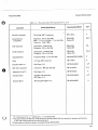
Table 1-3. Parts Required for 86290B Options
Option
Reference Designator
Wl1
J9
J10
86290-00004
86290-00023
86290-20031
86290-60005
1250-0118
Panel: Front Lower
Cover: Rear Panel
RF Cable: RF Coupler to Output
Connector: RearRF Output
Connector: Rear EXT ALe INPUT
Jl
86290-60007
Connector: APC-7
004
005
Description
HP Part No.
1-9
General Information
Model 8629GB
Table 1-4. Recommended Test Equipment (1 of 2)
Instrument
Critical Specifications
Recommended Model
Use*
P,A,T
Sweep Oscillator
No substitute mainframe
HP8620C
Spectrum Analyzer
(with external mixer)
Frequency Range: 2.0 GHz to 40 GHz
lIP 8555A/8S52B/141T
HPl1517A
P
Oscilloscope with DualTrace Vertical Amplifier
Vertical Amplifier: Dual trace with 10: 1 probes
Bandwidth: 20 MHz minimum
Vertical Sensitivity: 5 mV/Div
Horizontal Sweep Rate: 1 Ils/Div minimum
HP 182C/1801A/1820C
P,A,T
10:1 Divider Probe
For use with Oscilloscope
Range: -SOV to +50V
Accuracy: ±0.004%
Input Impedance: 10 megohms minimum
lIP 10004A
HP 3460B
Swept Amplitude Analyzer
and Oscilloscope
Mainframe
Frequency Range: 100 MHz to 18.6 GHz
HP 8755B/182T
A
Detectors (2 required)
Frequency Response: 0.1 - 18.6 GHz,
Error < 1.3 dB
Impedance: 50 ohms
lIP 11664A
A
Frequency Counter
Range: 2.0 to 18.6 GHz
lIP 5340A, Option H10
P,A
Function Generator
Frequency: 10 Hz to 2 MHz
Output: 6V p-p into 50 ohms
HP 3310A
P,A
RMS Voltmeter
Scale: RMS volts
Range: 0 to -70 dB
Accuracy: ±5%
Frequency Range: 10 Hz to 100 kHz
lIP 3400A
P
Power Meter/Thermistor
Mount and 10-dB
Attenuator
~C Power Supply
Frequency: 100 MHz"to·18.6 GHz
Range: +10 dBm to -20 dBm
HP 432A/8478B, H-32**
Range: 0 to 10 Vdc
Current: 0.1 Amp
HP 721A
Adjustable AC Line
Transformer
Output: 100 to 150 Vac
Power: 150 watts
General Radio MT3A
P
Frequency Meter
Range: 2.0 to 4.2 GHz
HP 536A
P
Frequency Meter
Range: 3.7 to 12.4 GHz
HP 537A
P,A
Frequency Meter
Range: 12.4 to 18.6 GHz
HPP532A
P
Adapters (2 required)
Type N Female to Waveguide
HP P281B, Option 013
P
Power Splitter
Frequency: 2 - 18.6 GHz
Attenuation in each arm: 6 dB
HP 11667A
P
Directional Coupler
Freq: 2.0 - 18.6 GHz
Coupling: 20 dB
Directivity: >25 dB
SWR all ports: < 1.3
Type-N Male Connector at Input port
Type N Female Connectors at Output
and Auxiliary Ports.
HP 11691D,
Option CO-2
P
DC Digital Voltmeter
1-10
A,T
A,T
P,A
P
';\.0-
General Information
Model 86290B
Table 1-4. Recommended Test Equipment (2 of 2)
Instrument
Recommended Model
Critical Specifications
Use*
~
~
Air Line (2 required)
20-cm long, APe-7 connectors
lIP 11567A
P
Crystal Detector
(2 required)
Frequency: 0.01 to 18.6 GHz'
SWR: < 1.5 to 12.4 GHz < 1.7 to 18.6 GHz .
Connector: Type N Male
HP8470B,.
Option 012
P,A,T
3 dB Attenuator
Attenuation: 3 dB ±0.3 dB
Frequency: DC to 18.6 GHz
lIP 8491B,
Option 003
P,A
10 dB Attenuator
Attenuation: 10 dB ±0.5 dB
Frequency: DC to 18.6 GHz
HP 8491B,
Option 010
P,A,T
Adjustable Short
Frequency Range: 2.0 to 18.6 GHz
Microlab/FXR SO-6MN
P
Cable
2-ft.long, BNC connectors
lIP 11086A
P
Extender Cable ***
(See Figure 1-3.)
HP 08620-60032
A,T
BNC Tee (2 required)
Connectors: BNC jack and plug
HP 1250-0781
P,A
Adjustment Tool***
(See Figure 1-3.)
HP 8830-0024
A
Extender Board
Supplied with instrument
(See Figure 1-1.)
HP 86290-60020
A,T
Extender Board
Reversing (See Figure 1-4.)
HP 86290-60033
A
':\..--
*p = Performance Test; A = Adjustments; T = Troubleshooting
**Thermistor Mount (8478B) and to-dB Attenuator (8491B, Option 010) are matched for optimum performance
to 18.6 GHz. This matched set is an HP 8478B, H-32.
***These parts are included in Service Accessories Package 08620-60124.
I-II
General
Model 8629GB
Informat~on
Item
•
•
•
•
Name
' Extender Cable
Adjustment Tool
Part No.
08620-60032
8830-0024
Use
Moves RF Plug-in outside mainframe for
alignment or service.
Fits miniature adjustment slot on
potentiometers.
36-Pin Service Board
08620-60037
Allows probing RF Section interface connector, or rear-panel programming connector on
all mainframes except 8620C, during performance testing or troubleshooting of 8620
Series mainframes.
50-Pin Service Board
08620·60125
Allows probing rear-panel programming
connector during performance testing or
troubleshooting of HP Model 8620C Sweep
Oscillator mainframe.
Figure 1-3.. Service Accessories, HP Part Number 08620-60124
1-12
Model 86290B
General Information
Figure 1-4. Reversing,Extender Board, 86290-60033
o
36-Pin Male Connector (2 x 18) HP Part No. 1251-0483
•
36-Pin' Female Connector (2 x 18) HP Part No. 1251-0484
•
I-inch 20-Gage Wire HP Part No. 8151-0011
Figure 1-5. RF Section 36-Pin Extender, 08621-60056
1-13/1-14
Model 86290B
Ins tallati on
SECTION II
INSTALLATION
2-1.
INTRODUCTION
2-2. This section provides installation instructions
for the Model 86290B RF Plug-in and its accessories. This section also includes information
about initial inspection and damage claims,
preparation for using the RF Plug-in and packaging, storage and shipment.
2-3.
INITIAL INSPECTION
2-4. Inspect the shipping container for damage.
If the shipping container or cushioning material is
damaged it should be kept until the contents of the
shipment have been checked for completeness and
the instrument has been checked mechanically and
electrically. The contents of the shipment should
be ~s shown in Figure 1-1. Procedures for checking
electrical performance are given in Section IV. If
the instrument combination does not pass the electrical performance tests, refer to the 8629GB Adjustments (Section V) in this manual. If, after the
86290B Adjustments have been made, the instrument combination still fails to meet specifications,
refer to mainframe Adjustments in the 8620C
mainframe manual. If a circuit malfunction is
suspected, refer to troubleshooting information in
Section VIII of this manual or 8620C mainframe
manual. If the instrument does not pass the above
electrical tests, or if the shipment contents are incomplete, or if there is mechanical damage or
defect, notify the nearest Hewlett-Packard office.
If the shipping container ·is, damaged, or the
cushioning material shows signs of stress, notify
the carrier as well as the Hewlett-Packard office~
Keep the shipping materials for carrier's inspection. The HP office will arrange for repair or
replacement without waiting for claim settlement.
2-5.
PREPARATION FOR USE
2-6.
Power Requirements
2-7. When the Model 86290B RF Plug-in is properly installed, it obtains all power through the
rear interface connector from the 8620C Sweep
Oscillator mainframe.
2-8.
Interconnections
2-9. For the Model 86290B RF Plug-in to
operate, it must be plugged into an 8620C mainframe. Connection is made by pushing the RF
Plug-in into the mainframe so that the plug-in interface connector PI mates with the mainframe
connector.
2-10. Mating Connectors
2-11. All of the externally mounted connectors
on the 86290B are listed in Table 2-1. Opposite
each 86290B connector is an industry identification, the part number of a mating connector, and
the part number of an alternate source for the
mating connector.
2·12.
Operating Environment
2·13. Temperature. The instument may be
operated in temperatures from O°C to + 55°C.
2-14. Humidity. The instrument may be operated
in environments with humidity from 5% to 95%
at 0° to 40 C. However, the instrument should be
protected from temperature extremes which cause
condensation within the instrument.
0
2·15. Altitude. The instrument may be
operated at altitudes up to 4572"metres (15000
feet).
2·16.
Frequency Scale Installation
2-17 . To install frequency scale, proceed as
follows:
NOTE
If RF Plug·in is installed in mainframe, it must be removed to install
frequency scale. See RF Plug-in
removal instructions in Paragraph
2·20.
a.
Disengage mainframe front-pane11atch handle, shown in Figure 2-1, by pushing
downward on handle while pushing inward
lightly on top of front panel.
2-1
Model 86290B
Installation
Table 2-1. Model 86290B-Mating Connectors
86290B Connector
Connector Name
J1 RFOUTPUT
Industry Identification
TYPE-N
Mating Connectors
Part Number
Alternate Source
1250-0882
~!z.
J2 ALC EXT INPUT
BNC
1250-0256
Specialty Connector
25Pl17-2
Specialty Connector
28 Pl18-1
J3 SEQ SYNC
BNC
1250-0256
Specialty Connector
28 Pl18-1
J4FM
BNC
1250-0256
Specialty Connector
28 Pl18-1
J5 FREQREF
BNC
1250-0256
Specialty Connector
28 Pl18-1
J6AUXOUT
TYPE-N
1250-0882
Specialty COJUlector
25P117-2
EXPLODED VIEW OF MAINFRAME
FRONT-PANEL LATCH HANDLE
(SHOWN IN LOCKED POSITION)
FRONT-PANEL lATCH HANDLE
(SHOWN IN DISENGAGED POSITION)
Figure 2-1. Location ofMainframe Parts Pertinent to Frequency Scale and RF Plug-in I.nstallation
2-2
Installation
Model 86290B
. b.
c.
~
Swing front panel forward and down to position shown in Figure 2-2.
To prevent damage to frequency
pointers when bandswitch drum is
rotated, make certain that frequency
scale is firmly in place and flush with
band drum edges.
Depress mainframe front-panel BAND select
lever, shown in Figure 2-1, to rotate frequency scale drum until desired scale position is accessible.
~f.'
f.
Return front panel to upright (closed) position and, while pushing inward lightly on top
of front panel, re-engage front-panel latch
handle by pushing it upward to lock position
as shown in Figure 2-1, exploded view.
NOTE
If necessary to remove a frequency
scale, exert a pressure OUTWARD,
away from drum on right-hand edge
of scale.
2-18.
RF Plug-in Installation and Removal
2-19. Installation. To install RF Plug-in, proceed as follows:
d.
e.
Insert frequency scale So key (a 1/16-inch
long, 1/2 inch wide protrusion) on left end of
scale fits into notch, shown in Figure 2-2, in
roller on left-hand edge of drum.
Push inward on-right-hand edge of frequency
scale to snap it in place in frequency scale
drum.
BAND INDICATOR
NOTCH
a.
If mainframe power is ON, press mainframe
LINE switch to OFF position.
b.
Position latch handle located on left side of
RFPlug-in so it is perpendicular to front
panel. Portion of ,handle with rectangular
cut-ont should be facing forward and portion
with notch should be facing rear ofRF Plug-in
as shown in Figure 2-3.
FREQUENCY SCALE DRUM
DEPRESSION
Figure 2-2. Mainframe Front Panel in Open Position
2-3
Installation
c.
d.
Model 86290B
Slide RF Plug-in into mainframe towards rear
of compartment. RF Plug-in latch handle will
engage a locking pin, shown in Figure 2-1,
inside mainframe and exposed portion of
latch handle will start to move downward.
Push latch handle downward, while still
pushing inward on RF Plug-in, until latch
handle is flush with front panel.
2·20. Removal. To remove RF Plug-in, proceed as follows:
a.
Push inward on top of latch handle, shown in
Figure 2-3, and pull forward and up on bottom of latch handle.
b.
When exposed portion of latch handle is in a
position perpendicular to RF Plug-in front
panel, it is disengaged from locking pin (Figure 2-1) and RF Plug-in may be removed by
pulling forward on latch handle.
2-21.
STORAGE AND SHIPMENT
2-22.
Environment
2-23. The instrument may be stored or shipped in
environments within the following limits:
-40°C to + 75°C
5% to 95% at.OOto 40°C
Up to 15240 metres
(50000 feet)
!~~'. •••••.•.•
Temperature
Humidity
Altitude
.
The instrument should also be protected from
temperature extremes which cause condensation
within the instrument.
2-24.
Packaging
2-25. Original Packaging. Containers and materials identical to those used in factory packaging
are available through Hewlett-Packard offices. If
NOTCH
LATCH
HANDLE
RECTANGULAR
CUT-OUT
Figure 2-3. RF Plug-In Latch in Release Position
24
:_:1"
Model 86290B
the instrument is being returned to HewlettPackard for servicing, attach a tag indicating the
type of service required, return address, model
number, and full serial number~ Also, mark the
container FRAGILE to ensure careful handling. In
any correspondence, refer to the instrument by
model numbe~ and full serial number
2-26. Other Packaging. The following general
instructions should be used for re-packaging with
commercially available materials:
a.
Wrap instrument in heavy paper or plastic. (If
shipping. to Hewlett-Packard Office or Service Center, attach tag indicating type of service required, return address, model number
and full serial number.)
Installation
b.
Use a strong shipping container.
c.
Use enough shock-absorbing material
around all sides of instrument to provide firm
cushion and prevent movement inside container. Protect control panel with cardboard.
d.
Seal shipping container securely.
e.
Mark shipping container FRAGILE to ensure
careful handling.
f.
In any correspondence, refer to instrument
by model number and full serial number.
2-5/2-6
Model 8629GB
Operatior
SECTION III
OPERATION
,I
3-1.
NOTE
INTRODUCTION
3-2. This operating section explains the function
of the controls and indicators of the Model 86290B
RF Plug-in. It decribes typical operating modes in
a measurement system and covers operator
replacement of indicator lamps. Figure 3~12 shows
the positions of the ALC Function switch AISI
that the.operator sets for each application.
3~.
PANEL FEATURES
3-4! Front and rear panel features are described
in Figures 3-2 and 3-3. Description numbers match
the numbers on the illustration.
3-5.
OPERATOR'S CHECKS
3-6. The Operator's Checks (Figure 3-4) allow
the operator to make quick evaluation of the instrument's main functions prior to use. These
checks assume that the 86290B RF Plug-in is installed in an 8620C Sweep Oscillator mainframe.
The checks cover the RF Plug-in and mainframe;
therefore, if the correct indications are not obtained, trouble may be in either of the units. If the RF
Plug-in is suspected, perform applicable performance tests in Section IV of this manual, and if
necessary, .the related adjustments in Section V. If
. correct indications are still not obtained, refer to
the troubleshooting information in Section VIII to
isolate the problem.
3-7.
t
I
OPERATING INSTRUCTIONS
I
WARNING
I
Any interruption of the protective
(grounding) conductor (inside or
outside the instrument) or disconnecting the protective earth terminal
could make this instrument dangerous.
Instrument may not meet maximum
leveled power specifications when
UNLEVELED lamp is lit.
3-8.
Internal Leveling
3-9. The most convenient method of RF outpu
leveling is internal leveling. A portion of the RI
output is coupled from a Directional Coupler DC~
to a Detector CR1. A proportional dc-voltage i:
applied to an operational amplifier in the 86290E
ALC Amplifier Assembly AI. The Operator':
Checks in Figure 3-4 are performed in the interna
leveling mode.
3-10.
External Power Meter Leveling
3-11. Power leveling can be obtained with :
power meter and power splitter or direction~
coupler as shown in Figure 3-10. A sample ofth.
RF output signal is routed to a power meter tc
produce a dc voltage proportional to the RF signa
level. The de voltage is applied to the 86290B AL(
circuits and compared with an internal referenct
voltage. A difference voltage is produced and am
plified by the ALC amplifier before being applied
as modulator drive, to the Coupler/Modulator as
sembly AIO. The modulator drive controls thl
output of the Coupler/Modulator to maintain '
constant power level.
·;v
3-12.
External Crystal Detector Leveling
3-13. Power may be leveled externally using;
power splitter (or directional coupler) and crysta
detector. This leveling system uses a power splitte
to sample the RF output signal and a crystal detec
tor to produce a dc voltage proportional to Rl
signal level. The detector voltage is compared witl
an internal reference voltage, and the differenc
voltage .changes the output power level to keep i
constant at the output. Instead of a power splitteI
a directional coupler may be used to sample the R:
signal for the leveling loop. Directional coupler
are usually narrow band, whereas the power spli1
ter is flat over a wide frequency range. The ac
vantage of a directional coupler is that it does ne
have a 6-dB loss like the power splitter, therefore
3-
Operation
higher maximum leveled power output may be obtained. To place the crystal detector leveling loop
in operation, use the test setup and procedures in
Figure 3-11.
3-14. Internal AM
3-15.
The 8620C Sweep Oscillator mainframe
has an internal 1 kHz square wave for internal
amplitude modulation of the RF signal. This provides an ON/OFF ratio of <25 dB for all bands of
the 86290B.
3-16.
External AM
3-17. The 86290B RF Output (CW) signal can be
amplitude modulated from 0 to 100% using an external mod'ulating signal applied to the mainframe
EXT AM connector. This provides an ON/OFF
ratio of > 30 dB for all bands of the 86290B. A
positive 5 volts input reduces the RF power output
.to at least 30 dB below specified maximum power.
3-18.
External FM
3-19. The 86290B RF Output signal can be frequency modulated using an external modulating
signal applied to the 86290B FM Input connector.
The external FM function provides a means of
obtaining an output frequency that varies under
the control of an external modulation signal. A
positive going voltage causes output frequency to
decrease while a negative going voltage causes
output frequencx to increase.
3-20.. Frequency Reference
3-21. A sweep signal output is available at the
rear':panel FREQ REF connector J5 for phaselocking external equipment. The sweep signal is
approximately + 1V/GHz.
3-22.
Phase-Lock Operation
3-23. The 86290B RF Output (CW) signal may be
phase-locked using an external phase-lock signal
applied to the 86290B FM Input connector. The
phase-lock function provides a means ofobtaining
a very stable CW frequency by transferring the
frequency stability of the reference oscillator to
the source. If the CW frequency starts to drift, the
phase difference between the CW frequency and
the reference frequency (reference oscillator) is
detected, producing a de voltage. The dc voltage is
a correction signal which restores the CW frequency to its previous point. Stability of this CW
frequency is determined by the stability of the
reference oscillator.
3-2
Model 86290B
3-24.
X-V Recorder Operation
3-25. In Sequential Sweep operation (Band 4),
the power output of the 86290B goes to zero at
each switchpoint for a brief time interval. This is
approximately 6 ms between Band 1 and 2 and
approximately 8 ms between Bands 2 and 3. (See
Section VIII for a Cbmplete explanation of Sequential Sweep operation.)
3-26. When an X-Y Recorder is used to plot the
detected RF amplitude from the 86290B, the
recorder's frequency response is not adequate to
respond fully to this" zero-power" interval and
will indicate a small negative going spike only. The
width of this spike is a function of sweep speed,
and is essentially zero for sweep times greater
than 20 seconds.
3-27. Recorders without DELAY MUTE
capability will display the "zero-power" spikes at
each switchpoint and is unavoidable. However, information loss caused by the spikes can be
eliminated by using a slow enough sweep time
«20 sec). Recorders with DELAY MUTE
capability can be operated so that "zero-power"
spikes are eliminated. This is accomplished by connecting the 86290B SEQ SYNC rear-panel output
to the X- Y Recorder DELAY MUTE input. Using
this DELAY MUTE feature will give a "glitch"
free plot for test devices that have relatively flat
responses at the switch point frequencies.
However, test devices having a rapid rate of
change across a switch point, such as the Band
Pass filter illustrated in Figure 3-1, may still show
a slight "glitch." Since it may not be immediately
apparent that the "glitch" is caused by the.:'lest
setup rather than the device under test, it is recommended that a reference plot be made using the
X- Y Recorder PEN LIFT input whenever "glitches" appear in the test device output near the 6.2
GHz and 12.4 GHz switch-point frequencies. The
PEN LIFT Input will not affect the switch-points,
therefore the source of the "glitch" can be easily
recognized. This is illustrated in Figure 3-1.
3-28. Retrace time of the 8620C mainframe,
when using an 86290B is much faster than sweep
time. When RF Blanking is used, 86290B power
output goes to zero during retrace. If an X- Y
Recorder is connected, the recorder pen will not
be able to go to "zero-power" as rapidly as the
86290B. Therefore, the retrace line on the X-Y
Recorder will not resemble actual RF response.
This can be improved by placing the mainframe
rear-panel RF BLANKING/OFF switch in the
Model 86290B
Operation
6 GHz
SWITCH POINT
12.4 GHz
SWITCH POINT
REFERENCE PLOT
WITHOUT DELAY MUTE
"GLITCH"
(CAUSED BY
12.4 GHz
SWITCH POINT)
REFERENCE PLOT
WITH DELAY MUTE
RESPONSE PLOT OF
DEVICE UNDER TEST
WITH DELAY MUTE
Figure 3-1. Typical Recorder Plot of Device Under Test and Reference Plots
OFF position. If a "zero-power" reference line is
desired, one may be drawn by triggering a single
sweep with 86290B power off (front-panel RF ONOFF switch OFF).
3-29.
X-V RECORDER MODIFICATION KIT
3-30. A modification kit is available to convert
older X-Y Recorders to obtain DELAY MUTE
capability. See the X-V Recorder Operating and
Service Manual or contact your nearest HewlettPackard Office for part number information. Ad-
dresses of HP Offices are provided at the rear of
this manual.
3-31.
OPERATOR'S MAINTENANCE
3-32. Operator maintenance on the 86290B consists of replacing defective front panel Band' indicator lamps. Removal and replacement procedures are contained in Figure 3-13.
3-33. Replacement of the UNLEVELED lamp is
shown in Section VIII as a maintenance procedure.
(See Figure 8-2.)
3-3
Operation
Model 8629GB
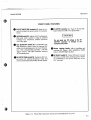
FRONT PANEL FEATURES
OFrequency/Band Display indicators A8D81 A8D84:
•
UNLEVELED lamp 081. Lights if output power is
unlevel across selected frequency range.
•
POWER LEVEL control Rl. Adjusts RF output
power. Clockwise rotation increases output
power.
•
ALe switch 82. Selects INT (internal), EXT (external), or MTR (power meter) power leveling
modes.
2.0 - 6.2 GHz.
Illuminates with Band
selected on mainframe.
6.0 -12.4 GHz. Illuminates with Band 2
selected on mainframe.
12.0 - 18.6 6Hz. Illuminates with Band 3
selected on mainframe.
1_-
2.0 -
18.6 6Hz. Illuminates with Band 4
selected on mainframe.
Band 4 is the Sequential
sweep.
Figure 3-2. Front Panel Controls, Connectors and Indicators (1 of 4)
3-4
Model 86290B
Operation
FRONT PANEL FEATURES
•
ALC EXT INPUT SNC connector J2. Input for externalleveling from power meter or crystal detector.
•
ALC GAIN control R4. Adjusts ALC leveling amplifter gain when system is using an external
leveling loop. Clockwise rotation increases
ALC loop gain.
•
•
ALC SLOPE-OFF control R3. Compensates for
high frequency power losses in external RF
cables by attenuating power at lower frequencies. This compensation provides a flat RF
signal output. The OFF Position removes
all compensation.
RF OUTPUT PEAK control R2. Optimizes RF output power for selected frequency range and
assures minimum harmonically related signals."
•
RF OUTPUT connector J1. Type-N 50-ohm RF
output cOnnector (APe-? for Option 005).
Do not apply any DC voltage to the RF
OUTPUT connector or damage to the
instrument may occur.
•
Drawer Latching Handle. Aids in installing an4
removing RF Plug-in. Mter installation, handle
-locks to hold RF Plug-in in place.
•
RF ON-OFF switch S1. Turns RF power on and
off. This is useful when zeroing a power meter
or establishing a zero power reference on an
X-y recorder.
.
Figure 3-2. Front Panel Controls, Connectors and Indicators (2 of 4)
3-5
Operation
Model 86290B
FRONT PANEL FEATURES
OPTION 004
o
Frequency/Band Display indicators
A8DS1-A8DS4:
•
POWER LEVEL control R1. Adjusts RF output
power. Clockwise rotation increases output
power.
•
ALC switch 82. Selects INT (internal), EXT (external), or MTR (power meter) power leveling
modes.
•
ALe GAIN control R4. Adjusts ALe leveling amplifier gain when system is using an external
leveling loop. Clockwise rotation increases
ALC loop gain.
•
ALC SLOPE-OFF control R3. Compensates for
high frequency power losses in external RF
cables by attenuating power at lower frequencies. This compensation, provides a leveled
RF signal output. The OFF position removes
all compensation.
2.0 - 6.2 GHz.
Illuminates with Band
selected on mainframe.
6.0 -12.4 GHz. Illuminates with Band 2
selected on mainframe.
12.0 -18.6 GHz. 'Illuminates with Band 3·
selected on mainframe.
•
2.0 -18.6'GHz. Illuminates with Band 4
selected on mainframe.
Band 4 is the Sequential
Sweep.
UNLEVELED lamp 081. Lights if output power is
unlevel across selected frequency range or if
automatic leveling is not used.
Figure 3-2. I:ront Panel Controls, Connectors and Indicators (3 of 4). Option 004
3-6
Operation
Model 86290B
FRONT PANEL FEATURES
OPTION 004
•
•
RF OUTPUT PEAK control R2. Optimizes RF
output power for selected frequency range and
assures minimum harmonically related signals.
Drawer Latching Handle. Aids in- installing and
removing RF Plug-in. After installing, handle
locks to hold RF Plug-in in place.
o RF ON-OFF switch S1.
Turns RF power on and
off. This is useful when zeroing a power meter
or establishing a zero power reference on an
X-V recorder.
Figure 3-2. Front Panel Controls, Connectors and Indicators (4 of 4), Option 004
3-7
Model 86290B
Operation
REAR PANEL FEATURES
o
•
e
•
Rear Panel Heatsink. Provides heat dissipatIon
and mounting for YTM and YTO
coil-driver transistors Ql and Q2, and reference resistors R5 and R6.
Interface Connector P1 .. Provides interconnection between 8620C mainframe and
86290B RF Plug-in.
AUX OUT J6. Provides YIG-tuned Oscillator RF
output signal of 2.0 - 6.2 GHz. (Cover provided should be installed whenAUX OUT not
used.)
FM-NORM-PL switch S3. Operates in conjunction with FM input connector to provide op-
timum performance for either normal sweep
(NORM), frequency modulation (FM), or
phase-lock (PL) operation. IfFM or PL modes
of operation are not being used, switch should
be in NORM.
•
FREQ REF BNC connector J5. Provides approximately + 1 volt/GHz ramp signal output.
•
FM BNC connector J4. Input connector for FM
modulation signal or phase-locking error
signal.
•
SEQ SYNC connector J3. Provides . RF blanking
output for timing signal to external equipment.
Figure 3-3. Rear Panel Connectors and Switch (1 of 2)
3-8
Model 86290B
Operation
REAR PANEL FEATURES
OPTION 004
•
Rear Panel Heatsink.
•
Interface Connector P1. Provides interconnection between 8620C mainframe and 86290B
Provides heat dissipation
and mounting for YTM and YTO coil-driver
transistors Q1 and' Q2, and reference resistors
RS and R6.
RF Plug-in.
•
AUX OUT J6.
Provides YIG-tuned Oscillator RF
output signal of 2.0 - 6.2 GHz.
o RF OUT connector
J9.
(APe-7
connector.
Type-N 50-ohm RF output
for Option ODS).
8
FM-NORM-PL switch S3.
Operates in conjunction with FM input connector to provide optimum performance for either normal sweep
(NORM), frequency modulation (FM), or phase
lock (PL) operation. If FM or PL lTIodes of operation are not being used, switch should be in
NORM.
o FR·EO REF+ BNC connector J5.
Provides approximately 1 volt/GHz ramp signal output.
•
EXT.ALC INPUT BNC connector J10.
Input for
external leveling from power meter or crystal
detector.
o FM BNC connector
J4. Input connector for FM
modulation signal or phase locking error signal.
Do not apply any DC voltage to the RF
OUTPUT connector or damage to the
instrument may occur.
•
SEO SYNC connector J3.
output for
ment.
timing signal
Provides RF blanking
to external equip-
Figure 3-3. Rear Panel Connectors and Switch (2 of 2), Option 004
3-9
Operation
Model 86290B
OPERATOR'S CHECKS
FRONT
REAR
Figure 3-4. Operator's Checks (1 of 4)
3-10
.-~
Model 86290B
Operation
OPERATOR'S CHECKS
SWEEP
OSCILLATOR
RF
PLUG-IN
Z-AXISI
MKRI
PEN LIFT
-
0
0
OSCILLOSCOPE
•- .
$!I
........
,/
--0
oe=-
0
0
=-:>
=-e
SWEEP
OUT
0
(
t{
0
.. e
0
...........
./
,..
••
•
Z-AXIS
INPUT
RF
OUTPUT
h•
~0
EXT
HORIZ
INPUT
• • • • (4
o· ·0
10-dB
ATTENUATOR
CRYSTAL
DETECTOR
{):::J
.@. ?@O
VERT
INPUT
@.@
~
'0
0 •••.
••••••
0
EQUIPMENT:
HP 8620C
Sweep Oscillator
RF Plug-in . . . . . . . . . . . . . . . . . . . . . . . . . . . . . . . . . . .. HP 86290B
Oscilloscope
HP 182C/1801N1820C
Crystal Detector
HP 8470B, Option 012
10-dB Attenuator
HP 8491B, Option 010
~
Do not apply any. DC voltage to the RF OUTPUT connector
or damage to the-instrument may occur.
NOTE
All procedures are written using the 8620C Sweep
Oscillator. The 862908 will not operate with an 8620A or
86208 mainframe.
PROCEDURE:
1.
Connect equipment as shown in test setup.
2.
Set controls as follows:
8620C:
BAND •
.
BAND 4, 2.0 - 18.6 GHz
MARKERS. .
INTEN
MODE •............... -;
INT
TIME-SECONDS
1 - .01
TIME-SECONDS Vernier fJ!)
Clockwise
1 kHz SQ WV/OFF (rear panel)
OFF
DISPLAY BLANKING/OFF
(rear panel)
DISPLAY BLANKING
RF BLANKING/OFF (rear panel). .
OFF
fa
ED
f.D
Figure 3-4. Operator's Checks (2 of 4)
3-11
Operation
M'ode186290B
OPERATOR'S CHECKS
8629GB:
G 8
RF OUTPUT
#.~.
ON
POWER LEVELGJ
Fully clockwise
ALC
INT
SLOPE-OFF •.................................... OFF
FM-NORM-PL (rear panel) •
.
NORM (Normal)
•
•
•
4D
e
e,
3.
Press LINE pushbutton switch
to ON; LINE
and FJJLL
SWEEP
pushbuttons should light. The 2.0 - 18.6 GHz lamp. should liiht on
86290B.
\~---//
4.
Check that the instrument is sweeping correctly. This is indicated by a continuous
signal-level line below zero-volt dc level on oscilloscope. Adjust PEAK
control
for maximum signal on oscilloscope.
0
G
5.
UNLEVELED lamp. may be lit. If UNLEVELED lamp is lit, reduce output power
by turning 86290B POWER LEVEL control. counterclockwise until UNLEVELED lamp goes out. This is .adjustment point for maximum leveled power. Oscilloscope
trace should be leveled. (Refer to Figures 3-5 and 3-6 for typical oscilloscope display of
Sequential Sweep unleveled and leveled RF Power Output. Refer to Figures 3-7 and
3-8 for single-band displays.)
6.
Set 8620C MARKERS switch
to INTEN position.! Markers should appear on
oscilloscope trace as bright dots. Adjust oscilloscope intensity for best contrast. Set
MARKERS switch to AMPL position. Markers should appear on oscilloscope trace as
pips.
7.
Set 8620C MODE switch f) to MANUAL position and slowly adjust MANUAL
control f) · Trace dot should move across oscilloscope. Return 8620C MODE switch
to AUTO.
8.
Press 8620C CW pushbutton
pushbutton should light and trace on oscilloscope
should be a dot. Change frequency
with CW MARKER control. Dot should move
across oscilloscope.
f.D
0;
0
Figure 3-4. Operator's Checks (3 of 4)
3-12
Operation
Model 8629GB
OPERATOR'S CHECKS
9.
e';
Press 8620C. CW VERNIER pushbutton switch
pushbutton should light. Adjust
CW VERNIER control. White pointer
above C]I VERNIER control should
move. Dot on oscilloscope should· also move across CRT at a very slow rate and
through a narrow range. CW VERNIER slide switch" selects a 0.1 multiplier (X.1
position) for CW vernier scale; in Xl position, scale is read directly. Press 8620CCW
pushbutton; CW VERNIER P·ushbutton lamp should turn off.
0
0 ;
10. Press 8620e ~F pushbutton
~F and ewe pushbuttons should be lit. Deviation
from ew frequency is selected by ~F control, and adjusting it moves white pointer
•
abovenF control. nF slide switch
selects a 0.1 multiplier (X. 1 position), a
1.0 multiplier (X 1 position), or a 10 multiplier (X I O' position).
fa
11. Adjust POWER LEVEL control. fully clockwise. Adjust 8620C ~F
control
between zero and maximum. Sweep trace should be displayed on oscilloscope and should change as ~F control is adjusted. _
0
Figure 3-4. Operator's Checks (4 0/4)
3-13
Operation
Model 86-290B
6.0 6Hz
12.0 6Hz
Figure 3-5. Unleveled RF Power Output
for Sequential·Sweep
Figure 3-6. Leveled RF Power Output
for Sequential Sweep
<1.4 dB
I
I
2.0 6Hz
6.26Hz
; Figure 3-7. Unleveled RF Power Output
for Single Band (Band 1)
Figure 3-8. Leveled RF Power Output
for Single Band (Band 1)
oVDC
t
POWER
OUTPUT
ALC LOOP
OSCILLATION
Figure 3-9. Oscillations Due to Excessive ALC Loop Gain
3-14
Model 86290B
Operation
i
(
EXTERNAL POWER METER LEVELING
SWEEP
OSCILLATOR
POWER
METER
RF
PLUG-IN
ooooo~t{o
o e==-
=-:0
=- e
SWEEP
OUT
RECORDER~
!.
EXT INPUT
OUTPUT
••
.. • ~-------------1"'" 0
•
RF
OUTPUT
THERMISTOR
MOUNT
OSCILLOSCOPE
•
•
HORIZ
EXT
•
INPUT
VI. ----.
I
I
10-dB
ATIENUATOR
CRYSTAL
DETECTOR
VERT
INPUT
LEVELED
POWER
OUTPUT
EQUIPMENT:
HP 8620C
Sweep Oscillator
RF Plug-in. . . . . . . . . . . . . . . . . . . . . . . . . . . . . . . . . . .. HP 86290B
Oscilloscope
HP 182C/1801N1820C
Power Meter
HP 432A
Thermistor Mount
HP 8478B
Crystal Detector
HP 8470B, Option 012
10-dB Attenuator
HP 8491B, Option 010
Power Splitter
HP 11667A
Do not apply any DC voltage to the RF OUTPUT connector
or damage to the instrument may occur.
NOTE
Power meter leveling should be used at slowest sweep rates.
Leveling is limited by response time of thermistor mount
PROCEDURE:
1.
Connect equipment as shown in test setup.
Figure 3-10. External Power Meter Leveling (1 of 2)
3-15
Operation
Model 86290B
EXTERNAL POWER METER LEVELING
2.
Set controls as follows:
8620C:
BAND
BAND 4, 2.0 - 18.6 GHz
MARKERS
OFF
MODE
AUTO
TRIGGER
INT
TIME-SECONDS
100 - 10
TIME-SECONDS Vernier
"
Fully clockwise
I kHz SQ WAVE/OFF (rear panel)
OFF
DISPLAY BLANKING/OFF (rear panel) ..DISPLAY BLANKING
86290B:
RF OUTPUT
POWER LEVEL
ALC
ALC-GAIN
FM-NORM-PL (rear panel)
ON
Fully clockwise
MTR (Power Meter)
Fully counterclockwise
NORM (Normal)
3.
Press 8620C LINE pushbutton to ON; LINE and FULL SWEEP pushbuttons should
light, indicating FULL SWEEP sweep mode is selected. The 2.0 - 18.6 GHz lamp
should light on 86290B.
4.
Select range on power meter to obtain indication near top 1/3 of meter scale.
5.
Adjust 86290B ALe GAIN control clockwise until leveling across band occurs as
shown in Figure 3-6. If trace is not leveled or is only partially leveled (as shown in
Figure 3-5) with ALC GAIN fully clockwise, reduce RF OUTPUT power. This is
done by adjusting POWER LEVEL control counterclockwise until leveling occurs as
shown in Figure 3-6. If oscillations appear on trace as shown in Figure 3-9, turn ALe
GAIN control counterclockwise. With proper leveling across the band, the 86290B
UNLEVELED light should be out.
6.
To use leveled RF Power output for testing external equipment, make connection at
point marked" "Leveled Power Output."
Figure 3-10. External Power Meter Leveling (2 0[2)
3-16
";c-
.~
Model ~86290B
Operation
EXTERNAL CRYSTAL DETECTOR LEVELING
SWEEP
OSCILLATOR
Z-AXISI
MKRI
PEN LIFT
RF
PLUG-IN
0
0
0
0
oec:=a
0
=-:0
=-e
SWEEP
OUT
0
•-
~
0
.. e
RF
OUTPUT
POWER
METER
CABLE
•• !.
~!<.
<1 FT
o •
EXT
INPUT
THERMISTOR
MOUNT
OSCILLOSCOPE
~---_.... --~
•
•
Z-AXIS
•
POWER
SPUTIER
EXT
HORIZ
INPUT
LEVELED
OUTPUT
POWER
INPUT
~0 • • • ~
~@~?@o
©.@
'-. '0
0 ••••
I,,:>'"
VERT
INPUT
CRYSTAL
DETECTOR
NOTE
Cables in the ALC loop must be kept <1 foot in length for best
ALC response.
EQUIPMENT:
Sweep Oscillator
HP 8620C
RF Plug-in. . . . . . . . . . . . . . . . . . . . . . . . . . . . . . . . . . .. HP 86290B
Oscilloscope
HP 182C/1801AJ1820C
Power Meter
HP432A
Crystal Detector (i required)
HP 8470B, Option 012
Power Splitter
HP 11667A
Directional Coupler
HP 11691D, Option CO-2
Thermistor Mount
HP8478B
PROCEDURE:
1.
Connect equipment as shown in test setup.
~
Do not apply any DC voltage to the RF OUTPUT connector
or damage to the instrument may occur.
NOTE
Crystal Detector output should be between 50 mVdc and
750mVdc.
Figure 3-11. External Crystal Detector Leveling (1 of 2)
3-17
Model 86290B
Operation
EXTERNAL CRYSTAL DETECTOR LEVELING
2.
Set controls as follows:
8620C:
BAND
BAND 4, 2.0 - 18.6 GHz
MARKER
OFF
MODE
AUTO
TRIGGER
INT
TIME/SECONDSVernier
Fully clockwise
1 kHz SQ WAVE/OFF (rear panel) .. ,
OFF
DISPLAY BLANKING/OFF (rear panel) ..DISPLAY BLANKING
86290B:
RF OUTPUT
ON
POWER LEVEL
Fully clockwise
ALC
EXT
ALC GAIN . . . . . . . . . . . . . . . . . . . . . . . . . . . . . . . Fully clockwise
FM-NORM-PL (rear panel)
NORM (Normal)
3.
Press 8620C LINE pushbutton to ON; LINE, and FULL SWEEP pushbuttons should
indicating FULL SWEEP mode is selected.. The 2. --- 18.6 GHz lamp should
light on 86290B.
ligl~t,
4.
Adjust ALC GAIN and POWER LEVEL controls fully clockwise for maximum RF
power OUTPUT and maximum ALC Loop gain. Adjust PEAK control for maximum
RF power. One ofthe conditions shown in Figures 3-5 through 3.. 9 should be displayed
on oscilloscope. If trace is unleveled as shown in Figures 3-5 or 3-7 (or partially
leveled) and UNLEVELED lamp is on, turn POWER LEVEL control counterclockwise until trace is level. (See Figures 3-6 and 3-8). If ALC loop gain is too high,
oscillations may occur as shown in Figure 3-9. To remove oscillations, reduce ALC
loop gain by turning ALC GAIN control counterclockwise.
5.
To use leveled RF power output for testing external equipment, make connection at
point marked "Leveled Output Power.'"
Figure 3-11. External Crystal Detector Leveling (2 of 2)
3-18
.,,1"
Operation
Model 86290B
A1S1 TOP
up*
1 2 3 4~5
0 - ..-- - - --
D
N
DOWN
to [] [] _ D
POSITIONS*
FUNCTIONS
1 and 2
Spares.
3 UP
Upper Clamp Removed (See Note 2 below).
DOWN
4 UP
Upper Clamp In (INT operation only)
Square Wave Modulation ON
DOWN
5 UP
No Modulation
Sine Wave Modulation ON
DOWN
Non linear modulation mode
Linear modulation mode
No Modulation
NOTE 1
Only one Modulation Mode should be UP (ON) at a time.
NOTE 2
In INTernal mode and when position 3 is DOWN, the 86290B
output power is clamped typically at +13 dBm by the Upper Power
Clamp on the A1 ALe Assembly.
*On some switches, the UP position is marked ON, on others, the DOWN position is marked with a dot.
Figure 3-12. Switch Positions and Functions for ALe Function Switch A1Sl
3-19
Operation
Model 86290B
BAND INDICATOR LAMP REPLACEMENT
1. . Press mainframe LINE switch to OFF positon.
2.
Remove 86290B RF Plug-In from mainframe.
3.
Remove front panel:
NOTE
If instrument has Option 004 (rear-panel RF OUT) installed,
proceed to step b.
4.
a.
Disconnect cable WI0 from RF OUTPUT connector Jl.
b.
Remove Drawer Latch Handle
by removing screw
and latch spring • .
Note position of spring. and location ofhole
for reinstalling.
c.
Remove four screws. from front panel (two on each side).
d.
Pull front panel out of frames.lightly and remove connector J7 from A7 Master
Board.
0
o
0
Remove and replace lamp:
a.
0
Lift contact spring
slightly and rotate it to expose base of lamp,
(A8DSI-A8DS4). Remove old lamp.
NOTE
Lifting the contact spring too far may bend it, reducing spring
tension.
b.
5.
Install new lamp and replace contact spring
0
over base.
Install front panel by reversing instructions in step 3.
Figure 3-13. Band Indicator Lamp Replacement (1 012)
3-20
Operation
Model 86290B
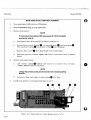
BAND INDICATOR LAMP REPLACEMENT (Cont'd)
OSl
OS2
AS
OS3
OS4
RF OUTPUT
Jl
Wl0
J7
• r•
Figure 3-13. Band Indicator Lamp Replacement (2 of2)
3-21/3-22
F/idl HEW·LETT
~~ PACKARD
Part of HP Part No. 86290-90028
Printed in U.S.A.