1
TM 11-6625-2917-14&P-14
Model 86260A
Installation
SECTION II
INSTALLATION
2-5. PREPARATION FOR USE
2-1. INTRODUCTION
2-2. This section provides installation instructions for the
Model 86260A RF Plug-in and its accessories.
2-6. Power Source
2-7. When the Model 86260A RF Plug-in is properly
installed, it obtains all necessary power through the rear
connector from the HP Model 8620A or 8620B Sweep
Oscillator mainframe.
2-3. INITIAL INSPECTION
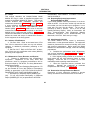
2-4. Inspect the shipping container for damage. If the
shipping container or cushioning material is damaged it
should be kept until the contents of the shipment have
been checked for completeness and the instrument has
been checked mechanically and electrically.
The
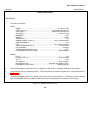
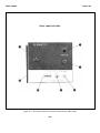
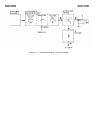
contents of the shipment should be shown in Figure 1-1,
and procedures for checking electrical performance are
given in Section IV.
2-8. Interconnections
2-9. For the Model 86260A RF Plug-in to operate, it
must be plugged into an 8620A or 8620B main- frame.
Connection is made by pushing the RF Plug- in into the
mainframe so that the plug-in interface connector P1
mates with the mainframe connector J6.
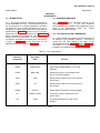
2-10. Mating Connectors
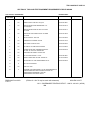
2-11. The mating connectors used in the HP Model
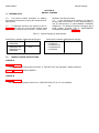
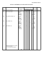
86260A RF Plug-in are shown in Table 2-1. This table
identifies each connector and gives the HP Part Number
and a part number of an alternate source.
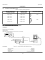
Table 2-1. Model 86260A Mating Connectors
Industry
Identification
Connector
HP Part
Number
Alternate
Source
RF OUTPUT J2
Type-N
86290-60005
FM Input J4
BNC
1250-0118
Amphenol RF Div
31-221-1022
ALC EXT INPUT J3
BNC
1250-0118
Amphenol RP Div
31-211-1022
FREQ REF J5
BNC
1250-0118
Amphenol Rf Div
31-221-1022
Interface P2
Micro-Ribbon 36
Contact Rack and
Panel Plug
1251-0483
Amphenol Corp.
57-10360-375
2-1