1
POWER STEERING (P/S) SYSTEM 3B1-7
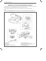
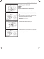
REMOVAL AND INSTALLATION POWER
STEERING GEAR BOX
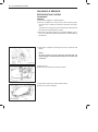
REMOVAL
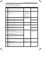
1) Perform steps 1) to 6) written in REMOVAL, POWER STEERING GEAR BOX, SECTION 3B1 in service manual mentioned
in FOREWORD of this manual.
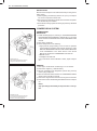
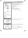
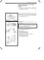
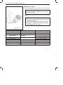
2) Remove engine mounting member and then remove engine
rear mounting bracket together with its mounting from engine.
3) Perform steps 9) to 11) written in REMOVAL, POWER STEERING GEAR BOX, SECTION 3B1 in service manual mentioned
in FOREWORD of this manual.
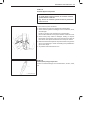
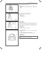
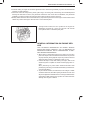
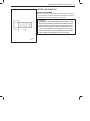
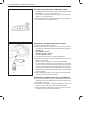
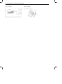
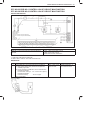
1. Engine rear mounting
2. Mounting bracket
3. Mounting member
4. Suspension frame
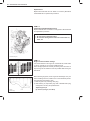
INSTALLATION
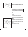
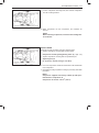
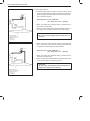
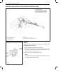
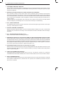
Reverse removal procedure for installation of steering gear box noting
the following points.
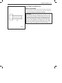
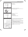
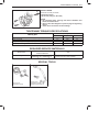
CAUTION:
Be sure to confirm that steering wheel and front tires
(wheels) are in straight position when inserting steering
lower joint into steering pinion shaft.
If a plug was put to disconnected pipe when removing steering gear
box, remove that plug before reconnecting pipe.
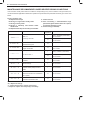
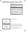
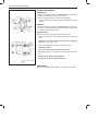
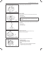
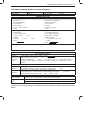
Use specified torque as given below.
Tightening Torque
(a): 55 N·m (5.5 kg-m, 40.0 lb-ft)
(b): 20 N·m (2.0 kg-m, 14.5 lb-ft)
(c): 35 N·m (3.5 kg-m, 25.5 lb-ft)
(d): 35 – 55 N·m (3.5 – 5.5 kg-m, 25.5 – 39.5 lb-ft)
(e): 25 N·m (2.5 kg-m, 18.0 lb-ft)
(f): 55 N·m (5.5 kg-m, 40.0 lb-ft)
(g): 45 N·m (4.5 kg-m, 32.5 lb-ft)
SY419
supple