1
i50 Manual (5.10)
Page 56
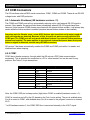
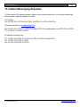
15.0 Programming Settings from DataGate
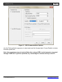
The DataGate server can send and receive individual i50 settings using the Remote Config button on
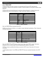
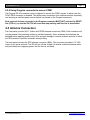
the Asset Properties window (Modems tab). Each setting is referenced by ID, with integer and string
values in separate lists. Many of these settings are crucial to the correct operation of the device, so
take care when making changes. These changes can also be made by an administrator via the
WebGate interface.
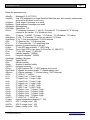
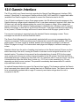
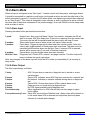
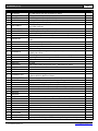
15.1 Integer Values
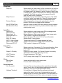
ID
0
Name
I_UPDATE
1
I_ALARMSTATE
2
3
4
5
6
7
8
9
10
11
I_IP1
I_IP2
I_IP3
I_IP4
I_PORTA
I_PORTB
I_PORTC
I_PORTD
I_PORTF
I_SATSPEED
12
I_EVENTS
13
14
15
16
17
18
19
20
21
22
23
24
25
26
27
28
29
30
31
32
33
34
I_ID1
I_ID2
I_ID3
I_INPUT1
I_INPUT2
I_INPUT3
I_INPUT4
I_USEINPUT1
I_USEINPUT2
I_USEINPUT3
I_USEINPUT4
I_INPOLARITY1
I_INPOLARITY2
I_INPOLARITT3
I_INPOLARITY4
I_USEIGN
I_OUTPUT1
I_OUTPUT2
I_OUTPUT3
I_OUTPOLARITY1
I_OUTPOLARITY2
I_OUTPOLARITY3
© 2015 Datalink Systems, Inc.
Default
Description
1
Update clock using GPS (1=Yes 0=No)
Alarm state. Bits 7-5 are response state. Bits 4-1 are alarm state. Bit 0 indicates 0
geofence on
Cellular IP address (also uses I_IP2-I_IP4). Range=0-255
“
"
"
0
PORTA (Program/COM1/WiFi) Port Setting. See note at bottom for values
0
PORTB (COM2) Port Setting. See note at bottom for values
0
PORTC (GPRS) Port Setting. See note at bottom for values
0
PORTD (Iridium) Port Setting. See note at bottom for values
0
PORTF (COM3) Port Setting. See note at bottom for values
7
PDT COM Speed. See note at bottom for values
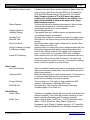
System Events (Firmware >= 4.77). Bit 2=Errors. Bit 1=Power Down. Bit
7
0=Power Up
255
Unit ID (also uses I_ID2 and I_ID3). Range=0-255
255
"
255
"
0
Input 1 Setting. See note at bottom for values
0
Input 2 Setting. See note at bottom for values
0
Input 3 Setting. See note at bottom for values
0
Input 4 Setting. See note at bottom for values
0
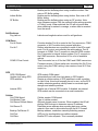
Send events when Input 1 changes. Bit 0=Low. Bit 1=High
0
Send events when Input 2 changes. Bit 0=Low. Bit 1=High
0
Send events when Input 3 changes. Bit 0=Low. Bit 1=High
0
Send events when Input 4 changes. Bit 0=Low. Bit 1=High
0
Input 1 polarity (0=Active Low 1=Active High)
0
Input 2 polarity (0=Active Low 1=Active High)
0
Input 3 polarity (0=Active Low 1=Active High)
0
Input 4 polarity (0=Active Low 1=Active High)
0
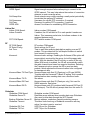
Send events when IGN changes. Bit 0=Low. Bit 1=High
32
Output 1 Setting. See note at bottom for values
32
Output 2 Setting. See note at bottom for values
32
Output 3 Setting. See note at bottom for values
1
Output 1 polarity (0=Low 1=High)
1
Output 2 polarity (0=Low 1=High)
1
Output 3 polarity (0=Low 1=High)
www.datalinksystemsinc.com