1
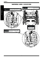
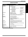
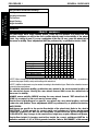
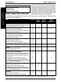
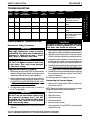
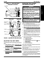
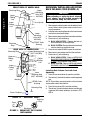
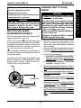
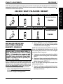
Service Manual
52;,-4c
DEALER: KEEP THIS MANUAL. THE PROCEDURES IN
THIS MANUAL MUST BE PERFORMED BY A QUALIFIED
TECHNICIAN ONLY.
WARNING
WARNING
W
A
R
N
I
N
G
DO NOT SERVICE, REPAIR OR OPERATE THIS EQUIPMENT
WITHOUT FIRST READING AND UNDERSTANDING THIS
MANUAL AND THE SPYDER OWNER'S MANUAL, PART
NUMBER 1093830. IF YOU ARE UNABLE TO UNDERSTAND THE
WARNINGS, CAUTIONS, AND INSTRUCTIONS, CONTACT A
HEALTHCARE PROFESSIONAL, DEALER OR TECHNICAL
PERSONNEL IF APPLICABLE BEFORE ATTEMPTING TO USE THIS
EQUIPMENT - OTHERWISE INJURY OR DAMAGE MAY RESULT.
THE INITIAL SET UP OF THIS WHEELCHAIR MUST BE
PERFORMED BY A QUALIFIED TECHNICIAN.
PROCEDURES DESCRIBED IN THIS MANUAL MUST BE
PERFORMED BY A QUALIFIED TECHNICIAN.
SAVE THESE INSTRUCTIONS
SPECIAL NOTES
S
P
E
C
I
A
L
N
O
T
E
S
WARNING/CAUTION notices as used in this manual apply to hazards or unsafe practices which
could result in personal injury or property damage.
NOTICE
THE INFORMATION CONTAINED IN THIS DOCUMENT IS SUBJECT TO CHANGE WITHOUT NOTICE.
WHEELCHAIR USER
As a manufacturer of wheelchairs, Invacare endeavors to supply a wide variety of wheelchairs to meet many needs of the end user. However, final selection of the type of wheelchair
to be used by an individual rests solely with the user and his/her healthcare professional
capable of making such a selection.
WHEELCHAIR TIE-DOWN RESTRAINTS AND SEAT POSITIONING STRAPS
Invacare recommends that wheelchair users NOT be transported in vehicles of any kind while in
wheelchairs. As of this date, the Department of Transportation has not approved any tie-down
systems for transportation of a user while in a wheelchair, in a moving vehicle of any type.
It is Invacare’s position that users of wheelchairs should be transferred into appropriate seating in vehicles for transportation and use be made of the restraints made available by the auto
industry. Invacare cannot and does not recommend any wheelchair transportation systems.
AS REGARDS RESTRAINTS - SEAT POSITIONING STRAPS - IT IS THE OBLIGATION OF THE DME DEALER,
THERAPISTS AND OTHER HEALTHCARE PROFESSIONALS TO DETERMINE IF A SEATING POSITIONING
STRAP IS REQUIRED TO ENSURE THE SAFE OPERATION OF THIS EQUIPMENT BY THE USER. SERIOUS
INJURY CAN OCCUR IN THE EVENT OF A FALL FROM A WHEELCHAIR.
2
TABLE OF CONTENTS
TABLE OF CONTENTS
SPECIAL NOTES ..................................................................................................................................... 2
LABELS ................................................................................................................................................... 4
SPECIFICATIONS .................................................................................................................................... 5
PROCEDURE 1 - GENERAL GUIDELINES ............................................................................................. 6
STABILITY ................................................................................................................................................ 6
TIRE PRESSURE .................................................................................................................................... 7
WEIGHT LIMITATION ................................................................................................................................ 7
PROCEDURE 2 - SAFETY INSPECTION ................................................................................................ 8
SAFETY INSPECTION CHECKLIST .......................................................................................................... 8
TROUBLESHOOTING ............................................................................................................................. 9
MAINTENANCE/TRANSPORTING ............................................................................................................. 9
PROCEDURE 3 - FRAME ...................................................................................................................... 10
ADJUSTING THE BACK ANGLE .............................................................................................................. 10
ADJUSTING THE REAR SEAT DUMP ..................................................................................................... 10
ADJUSTING THE SEAT WIDTH ...............................................................................................................11
REPLACING THE FOLDING MECHANISM ................................................................................................11
REMOVING/INSTALLING/ADJUSTING BACK RELEASE CORD ................................................................ 12
REPLACING OPTIONAL BACK UPHOLSTERY ....................................................................................... 14
ADJUSTABLE TENSION BACK UPHOLSTERY ....................................................................................... 15
PROCEDURE 4 - ARMS ........................................................................................................................ 16
INSTALLING T-ARM SOCKETS ............................................................................................................... 16
REPLACING THE T-ARM LOCKING LEVER ............................................................................................ 16
PROCEDURE 5 - CASTERS ................................................................................................................. 17
REPLACING/REPOSITIONING/INSTALLING FRONT CASTERS ............................................................... 17
INSTALLING/REPLACING FORKS........................................................................................................... 17
ADJUSTING CASTER HEADTUBES ....................................................................................................... 18
PROCEDURE 6 - REAR WHEELS ......................................................................................................... 19
ADJUSTING WHEELBASE WIDTH ......................................................................................................... 19
ADJUSTING REAR WHEEL CAMBER ..................................................................................................... 19
ADJUSTING REAR WHEEL HEIGHT ....................................................................................................... 20
ADJUSTING WHEELBASE LENGTH ....................................................................................................... 20
HANDRIMS ............................................................................................................................................ 21
PROCEDURE 7 - STABILITY ADJUSTMENTS ..................................................................................... 23
SEAT-TO-FLOOR HEIGHT DETERMINATION ......................................................................................... 23
CHANGING SEAT-TO-FLOOR HEIGHT ................................................................................................... 23
INSTALLING/ADJUSTING ANTI-TIPPER MOUNTING BRACKETS .............................................................. 31
INSTALLING/ADJUSTING THE ANTI-TIPPERS ......................................................................................... 32
PROCEDURE 8 - SUSPENSION ........................................................................................................... 34
ELASTOMERS AND SUSPENSION ........................................................................................................ 34
REPLACING FRONT ELASTOMERS ...................................................................................................... 34
3
T
A
B
L
E
C
O
N
T
E
N
O T
F S
LABELS
WARNING LABEL LOCATIONS
WARNING
L
A
B
E
L
S
WARNING
Pinch point. To unfold, grasp top edge ONLY.
1097049
Rev. ARev.
(1)A (1)-3/00
3/00
P/N 1097049
DO NOT step or stand on rear folding links. 1097061
Otherwise, injury or damage may occur.Rev.A (1)3/00
WARNING
DO NOT OPERATE
WITHOUT THE ANTI-TIP
TUBES INSTALLED.
REV. 5/98
WARNING
Detent balls should extend beyond the diameter
of the axle bushing for a positive lock. Keep
detent balls clean.
REV.10/98
1026960
4
P/N 60106X144
SPECIFICATIONS
SPECIFICATIONS
SPYDER
SPECIFICATIONS
Seat Width:
Seat Depth:
Seat-to-Floor:
14 to 20-inches
14 to 18-inches
REAR Seat-to-Floor Range
20-inch rear wheels 22-inch rear wheels 24-inch rear wheels and 559 rear wheels 26-inch rear wheels -
14-1/4 to 18-1/4-inches
14-1/2 to 19-inches
15-1/2 to 20-inches
16-1/2 to 20-inches
FRONT Seat-to-Floor Range
3-inch Front Casters 5-inch Front Casters 6-inch Front Casters 8-inch Front Casters -
16-3/4 to 17-1/4-inches
17 to 19-inches
18 to 19-1/2-inches
20-inches
o
Back Height:
Push Handles - 10 bend Sportster - No Push Handles Straight with Push Handles -
Footrest:
60 , 70 , 90 - Swingaway, Tapered, Non-Tapered, Elevating Legrest,
Adjustable Angle Flip-up Footplates, Composite Footplates
Rear Axle:
Quick-Release, Quad-Release
Rear Wheels:
20, 22, 24-inch Composite Wheels
22, 24, 26-inch Spoke Wheels
24, 26-inch Hi-Performance Spoke Wheels
559 High Performance/Turbo Tire
OPTIONAL - 24, 26-inch Continental Tires, 22, 26-inch Pneumatic Tires,
Flat Free Inserts
Handrims:
Aluminum Anodized, Plastic Coated, Black Plastic Coated,
Vertical/Oblique Projection Plastic Coated, Spoke Guards
Wheel Locks:
High Mount Pull to Lock (Standard), Wheel Lock Extensions,
Hill Holder, Undermount Wheel Lock
Caster Size:
3, 5, 6 and 8-inch (Urethane or Pneumatic), Precision Sealed Bearings
Flat Free Inserts
Seat Cushion:
2 or 3-inch (Optional)
Back Upholstery:
Black Nylon (Optional), Adjustable Back Upholstery (Standard)
Weight:
29.6 lbs. - with Rear Wheels
20.4 lbs. - without Rear Wheels
44 lbs.
Shipping Weight (approx.)*:
o
o
16-18-inches and 20-inches
12-14-inches
12-18-inches
o
*14-inch Seat Frame with complete package.
5
S
P
E
C
I
F
I
C
A
T
I
O
N
S
PROCEDURE 1
This Procedure Includes the Following:
Stability
Operating Information
Tire Pressure
Weight Training
Weight Limitation
STABILITY
STABILITY WARNINGS
Seat Dump
Back Angle
Seating System
Caster Size
Caster Position
Rear Wheel Size
Rear Wheel Position
User Condition
●
✓
User Condition
Anti-Tippers
Rear Wheel Position
Rear Wheel Size
✓
✓
●
✓
✓
✓
●
✓
●
✓
Caster Position
Caster Size
Seating System
Back Angle
The seat dump, back angle, seating system, caster size and position, rear wheel size and
position, anti-tippers, as well as the user condition directly relate to the stability of the wheelchair. Any change to one (1) or any combination of the nine (9) may cause the wheelchair to
decrease in stability. These adjustments MUST be performed by a qualified technician ONLY.
Seat Dump
G
E
N
E
R
A
L
G
U
I
D
E
L
I
N
E
S
GENERAL GUIDELINES
✓
✓
✓
✓
✓
✓
✓
●
✓
✓
✓
✓
✓
✓
●
✓
✓
✓
✓
✓
✓
●
✓
✓
✓
✓
✓
✓
✓
●
NOTE: When changes to the left hand column occur, follow across the chart and refer to the ✓ procedure to
maintain the proper stability, safety and handling of the wheelchair.
NOTE: Additional adjustments may be needed according to the wheelchair type. Refer to the wheelchair owner's
manual for these procedures.
To maintain maximum stability, position the rear wheels in the most rearward position on
the wheelchair frame. Moving the rear wheels forward WILL cause the wheelchair to
decrease in stability.
ALWAYS ensure stability BEFORE moving the rear wheels forward. TEST wheelchair BEFORE it is occupied by the end user to ensure safety.
Seat-to-floor heights depend on specific rear wheel size, rear wheel position, and front
caster size and position. These adjustments MUST be performed by a qualified technician.
ANTI-TIPPERS
Anti-tippers are specific to the seat-to-floor height of the wheelchair. Refer to the chart in
PROCEDURE 7 of this manual for correct usage and adjustment. If these requirements
cannot be achieved, DO NOT use the wheelchair. Contact Invacare technical support at
1-800-832-4707. Any changes to the seat-to-floor height may require different anti-tippers.
Seat-to-floor height: If changing seat-to-floor height, the correct anti-tippers MUST be installed to maintain a 1-1/2 to 2-inch ground clearance. Refer to PROCEDURE 7 of this manual.
6
GENERAL GUIDELINES
PROCEDURE 1
GENERAL WARNINGS
Refer to PROCEDURE 1 - GENERAL GUIDELINES in the Spyder owner's manual for additional operating information.
Unless otherwise noted, all service and adjustments should be performed while the
wheelchair is unoccupied.
To determine and establish the user's particular safety limits, bending, reaching and
transferring activities in several combinations should be practiced in the presence of a
qualified healthcare professional BEFORE attempting active use of the wheelchair.
DO NOT use parts, accessories, or adapters other than those authorized by Invacare.
DO NOT attempt to lift a wheelchair by lifting on any removable (detachable) parts.
Lifting by means of any removable (detachable) parts of a wheelchair may result in
injury to the user or damage to the wheelchair.
Anti-tippers MUST BE attached at all times. Inasmuch as the ANTI-TIPPERS are an option
on this wheelchair (You may order with or without the anti-tippers), Invacare strongly
recommends ordering the anti-tippers as an additional safeguard for the wheelchair
user.
ALWAYS wear seat positioning strap. Inasmuch as the SEAT POSITIONING STRAP is an
option on this wheelchair (You may order with or without the seat positioning strap),
Invacare strongly recommends ordering the seat positioning strap as an additional
safeguard for the wheelchair user.
TIRE PRESSURE
DO NOT use wheelchair unless it has the proper tire pressure (p.s.i.). DO NOT overinflate
the tires. Failure to follow these suggestions may cause the tire to explode and cause
bodily harm.
Replacement of a pneumatic tire or tube MUST be performed by a qualified technician.
WEIGHT LIMITATION
The Invacare Spyder has a weight limitation of 250 lbs. (113.5 kg.).
7
G
E
N
E
R
A
L
G
U
I
D
E
L
I
N
E
S
PROCEDURE 2
S
A
F
E
T
Y
I
N
S
P
E
C
T
I
O
N
SAFETY INSPECTION
NOTE: Every six (6) months the wheelchair should be
serviced and thoroughly inspected by a qualified technician. Regular cleaning will reveal loose or worn parts and
enhance the smooth operation of your wheelchair. To operate properly and safely, your wheelchair must be cared
for just like any other vehicle. Routine maintenance will
extend the life and efficiency of your wheelchair.
This Procedure includes the following:
Safety Inspection Checklist
Troubleshooting
Maintenance/Transporting
SAFETY INSPECTION CHECKLIST
Initial adjustments should be made to suit your personal body structure and preference. Thereafter follow
these maintenance procedures:
ITEM
INITIALLY
INSPECT/
ADJUST
WEEKLY
GENERAL - TROUBLESHOOTING
Wheelchair rolls straight (no excessive drag or pull to one side).
Inspect folding front strap for wear and damage.
X
X
SEAT AND BACK UPHOLSTERY - PROCEDURE 3
Inspect for rips or excessive sagging.
Inspect fastening flaps to ensure they securely latch.
Inspect back release cord for wear.
X
X
X
WHEEL LOCKS
Do not interfere with tires when rolling.
Pivot points free of wear and looseness.
Wheel locks easy to engage.
X
X
X
REAR WHEELS
Axle plate is securely tightened.
Quick/Quad-release axles lock properly.
No excessive side movement or binding when lifted /spun.
X
X
X
HANDRIMS - PROCEDURE 6
Inspect for signs of rough edges or peeling finish.
X
SPOKES
Inspect for bent or broken spokes.
All spokes uniformly tight.
X
X
X
X
X
X
FRONT CASTERS - PROCEDURE 5
Inspect wheel/fork assembly for proper tension by
spinning caster; caster should come to a gradual stop.
Loosen/tighten locknut if wheel wobbles noticeably or
binds to a stop.
Wheel bearings are clean and free of moisture.
CAUTION: As with any vehicle, the wheels and
tires should be checked periodically for cracks and
wear, and should be replaced.
X
X
CLEANING
Clean upholstery and armrests.
Inspect axles are free from dirt, lint, and debris.
INSPECT/
ADJUST
PERIODICALLY
X
X
X
X
X
X
X
X
X
X
X
X
X
X
X
TIRES
Inspect for flat spots and wear.
If pneumatic tires check for proper inflation.
CAUTION: As with any vehicle, the wheels and
tires should be checked periodically for cracks and
wear, and should be replaced.
INSPECT/
ADJUST
MONTHLY
X
X
X
X
X
X
X
X
NOTE: Refer to the Spyder Owner's Manual, part number 1093830 for adjustment procedures not in this manual.
8
SAFETY INSPECTION
PROCEDURE 2
TROUBLESHOOTING
CHAIR
VEERS
RIGHT
CHAIR
VEERS
LEFT
SLUGGISH
TURN OR
PERFORMANCE
CASTER
FLUTTERS
X
X
X
X
X
X
X
X
X
SQUEAKS
AND
RATTLES
X
LOOSENESS
IN CHAIR
CHAIR
3 WHEELS
X
SOLUTIONS
Check tires for correct
and equal pressure.
X
X
Check for loose stem
nuts.
X
X
Check spokes/nipples.
X
MAINTENANCE/TRANSPORTING
X
Check caster headtube
angle.
X
Check that rear wheels
are equally spaced away
from seat frame
(Procedure 6).
CAUTION
As with any vehicle, the wheels and tires
should be checked periodically for cracks
and wear, and should be replaced.
Maintenance Safety Precautions
WARNING
After ANY adjustments, repair or service
and BEFORE use, make sure all attachment
hardware is tightened securely - otherwise, injury or damage may result.
5. Check wheels and tires periodically for cracks and wear.
If damaged, have them replaced by a qualified technician.
CAUTION
7. Periodically check handrims to ensure they are secured to the rear wheels. If loose or damaged, have
them tightened or replaced by a qualified technician.
6. Regularly check for loose spokes in the rear wheels.
If loose, have them adjusted by a qualified technician.
DO NOT overtighten hardware attaching
to the frame. This could cause damage
to the frame tubing.
Suggested Maintenance Procedures
8. Periodically adjust wheel locks in correlation to tire wear.
Refer to REPLACING/ADJUSTING THE WHEEL LOCK
in the Spyder owner's manual, part number 1093830.
1. Before using your Invacare SPYDER, make sure all nuts
and bolts are tight. Check all parts for damage or wear
and replace. Check all parts for proper adjustment.
9. Periodically check caster wheel bearings to make sure
®
they are clean and free from moisture. Use a Teflon
lubricant if necessary.
2. Keep quick/quad-release axles free of dirt and lint to
ensure positive locking and proper operation. Refer
to ADJUSTING QUICK-RELEASE AXLES or ADJUSTING QUAD-RELEASE AXLES in the Spyder
owner's manual, part number 1093830.
10. Check upholstery for sagging, rips or tears.
3. Oil quick-release axles at least once (1) a month (3®
in-1 oil or equivalent).
NOTE: Refer to the Spyder owner's manual, part number
1093830 for the procedures mentioned below.
Transporting the Invacare Spyder
1. Remove the seating system. Refer to seating system owner's manual.
2. Remove the footrests.
WARNING
3. Remove the arms.
DO NOT use the wheelchair unless it has
the proper tire pressure (p.s.i.). DO NOT
overinflate the tires. Failure to follow these
suggestions may cause the tire to explode
and cause bodily harm.
4. Fold down the back.
5. Fold the wheelchair.
6. Remove the rear wheels.
7. After transporting, reverse STEPS 1-6 to prepare the
wheelchair for use.
4. Recommended tire pressure is listed on the sidewall
of the tire.
3-in-1 oil - Registered trademark of American Home Products Corporation.
Teflon - Registered trademark of E. I. Du Pont De Nemours and Company.
9
S
A
F
E
T
Y
I
N
S
P
E
C
T
I
O
N
PROCEDURE 3
F
R
A
M
E
FRAME
ADJUSTING THE REAR SEAT
DUMP (FIGURE 2)
This Procedure includes the following:
Adjusting the Back Angle
Adjusting the Rear Seat Dump
Adjusting the Seat Width
Replacing the Folding Mechanism
Removing/Installing/Adjusting Back Release Cord
Replacing Optional Back Upholstery
Adjustable Tension Back Upholstery
Seat dump is a measurement taken at the rear of the seat
from the horizontal position, and is measured in inches.
Refer to DETAIL “A” of FIGURE 2. The seat dump of the
Spyder can be adjusted in1/2-inch increments, up to 2-1/2inches below the front seat-to-floor height.
NOTE: Adjust both rear uprights to the same position.
1. Remove the bolt and locknut securing the rear upright to the wheelchair frame.
WARNING
2. Loosen, but do not remove the front and rear pivot bolt.
After ANY adjustments, repair or service
and BEFORE use, make sure all attachment
hardware is tightened securely - otherwise, injury or damage may result.
NOTE: Loosening the pivot nut allows the back angle to
remain the same in relation to the ground. No adjustment
is necessary to the back angle when adjusting seat dump.
3. Reposition the rear upright up or down and align the
mounting holes in the rear upright with the mounting
holes in the frame until the desired seat dump is
achieved. Refer to the chart below.
ADJUSTING THE BACK ANGLE
(FIGURE 1)
WARNING
SEAT DUMP REAR UPRIGHT
(INCHES)
HOLE
BEFORE performing this procedure, refer
to STABILITY in PROCEDURE 1 of this manual
for additional requirements.
0
1/2
1
1-1/2
2
2-1/2
1. Fold the back. Refer to FOLDING/UNFOLDING THE
BACK in PROCEDURE 5 of the Spyder owner's
manual, part number 1093830.
2. Remove the locknut and bolt at the top of the angle
bracket.
3. Reposition the bolt through one (1) of the four (4)
mounting positions in the angle bracket as shown in
FIGURE 1.
4. Install the locknut. Tighten securely.
FRAME
HOLE
C
B
A
B
A
B
1
1
1
2
2
3
4. Install the hex bolt and locknut in the mounting hole
determined in STEP 3 to secure the rear upright to
the wheelchair frame.
5. Tighten the front and rear pivot bolt.
5. Repeat STEPS 2-4 for the opposite back cane.
6. Unfold the back. Refer to FOLDING/UNFOLDING
THE BACK in PROCEDURE 5 of the Spyder owner's
manual, part number 1093830.
NOTE: Back angles are relative to the ground, NOT the seat.
BACK ANGLE
POSITIONS
Back
Cane
85° 90°
95°
Mounting Positions
Bolt
Locknut
Angle
Bracket
FIGURE 1 - ADJUSTING THE BACK ANGLE
10
100°
FRAME
PROCEDURE 3
REPLACING THE FOLDING
MECHANISM (FIGURE 3)
DETAIL “A” - REAR SEAT DUMP
MEASURED IN INCHES
Seat Rail
WARNING
Rear Pivot Bolt
NEW retaining rings MUST be used when
replacing the Spyder folding mechanism.
Existing retaining rings may become bent
during removal and may not properly secure the folding mechanism.
S E AT
DUMP
Front Pivot Bolt
Invacare strongly recommends using a
retaining ring insertion tool to install retaining rings. If not properly installed, the
retaining rings may become bent or damaged and injury may occur.
2-1/2
2
1-1/2
1
1/2
CAUTION
INSTALLED
REMOVED
Hole A
Hole B
Hole C
Hole 1
Rear
Upright
Pivot
Nut
Locknut
(NOT
SHOWN)
Hole 2
Bolt
Hole 3
Wheelchair Frame
FIGURE 2 - ADJUSTING THE REAR SEAT DUMP
ADJUSTING THE SEAT WIDTH
The following items MUST be replaced to adjust the seat
width:
1. Folding Mechanism. Refer to REPLACING THE
FOLDING MECHANISM in this procedure of the
manual.
2. Seat Upholstery. Refer to REPLACING SEAT UPHOLSTERY in PROCEDURE 4 of the Spyder
owner's manual, part number 1093830.
3. Back Upholstery. Refer to REPLACING OPTIONAL
BACK UPHOLSTERY or ADJUSTABLE BACK UPHOLSTERY in this procedure of the manual.
DO NOT use excessive force when removing or installing bushings. Otherwise, the
bushings may become deformed.
NOTE: The folding mechanism consists of ALL the folding links assembled to the center track.
1. Using a flat screwdriver, remove EXISTING retaining
rings securing bushings to the wheelchair frame.
2. Fold the wheelchair to remove tension on the bushings.
Refer to FOLDING/UNFOLDING THE WHEELCHAIR
in the Spyder owner's manual, part number 1093830.
3. Remove EXISTING bushings from wheelchair frame
with a punch or phillips screwdriver and a rubber mallet.
4. Remove EXISTING folding mechanism from the
wheelchair.
5. Align the folding links of the NEW folding mechanism
with the mounting holes on the wheelchair frame.
6. Insert the outer bushings UP through the following
items in the order listed:
A. LOWER mounting hole
B. LOWER folding link
C. CENTER folding link (REAR ONLY) OR spacer
(FRONT ONLY)
D. UPPER folding link
E. UPPER mounting hole
NOTE: Rear outer bushings should be inserted with the
frame protectors facing down.
NOTE: The lower notch on the rear outer bushing is above
the frame protector.
NOTE: Ensure the notches on the outer bushings are
above and below the wheelchair frame on either end.
7. Install one (1) new retaining ring onto each outer bushing notch using a retaining ring insertion tool.
NOTE: Ensure all three (3) tabs on each retaining ring are
completely inserted into the notch as shown in DETAIL
"A" of FIGURE 3.
11
F
R
A
M
E
PROCEDURE 3
FRAME
REMOVING/INSTALLING/ADJUSTING
BACK RELEASE CORD (FIGURE 4)
FRONT VIEW OF WHEELCHAIR
Upper
Mounting
Hole (NOT
SHOWN)
Retaining Ring
F
R
A
M
E
Upper
Folding
Link
WARNING
After adjusting or replacing back release
cord, ensure back is locked securely in
place BEFORE using the wheelchair.
Spacer
Lower
Folding
Link
Removing Back Release Cord
1. Remove back cushion/system from wheelchair, if necessary. Refer to back system owners manual for removal procedures.
2. Untie the knots securing the ends of the back release
cord to the back release latches.
Lower
Mounting
Hole (NOT
SHOWN)
Notches
3. Remove back release cord from back release latches.
4. Perform one (1) of the following:
A. BACK UPHOLSTERY - Remove the back release cord from the back upholstery.
FRONT Outer
Bushing
Retaining
Ring
B. BACK SYSTEM - Remove the back release cord
from the eyelets on each back cane.
REAR VIEW OF WHEELCHAIR
Retaining Ring
Upper Mounting Hole
(NOT SHOWN)
Upper
Folding
Link
5. Press the star wheel DOWN to open the cord lock.
6. Remove the back release cord from the cord lock.
7. Perform one (1) of the following:
A. BACK UPHOLSTERY - Refer to INSTALLING
BACK RELEASE CORD WITH BACK UPHOLSTERY in this procedure of the manual.
Center
Folding
Link
Lower
Folding
Link
Lower
Mounting Hole
(NOT SHOWN)
Notches
REAR Outer
Bushing
Retaining Ring
Frame Protector
B. BACK SYSTEM - Refer to INSTALLING BACK
RELEASE CORD WITH BACK SYSTEM in this
procedure of the manual.
Installing Back Release Cord with Back
Upholstery
1. Press the star wheel down to open the cord lock.
2. Thread one (1) end of back release cord through cord
lock.
NOTE: Ensure there are equal portions of back release
cord on either side of the cord lock.
3. Press the star wheel UP to lock the cord lock.
4. Thread one (1) end of the back release cord through
a grommet in the back upholstery as shown in FIGURE 4.
DETAIL "A" - RETAINING RINGS
Three
(3)
Tabs
Retaining
Ring
Bushing
FIGURE 3 - REPLACING THE FOLDING
MECHANISM
12
FRAME
PROCEDURE 3
5. Perform the following steps to secure the back release cord to the back release latch (DETAIL "B"):
A. Thread the end of the back release cord from STEP
4 through back release latch from the inside of the
wheelchair to the outside of the wheelchair.
B. Knot the end of the back release cord.
C. Pull knot up and over back release cord to make
a loop.
D. Push knot down and through back release cord
loop.
E. Grasp and hold knot end of back release cord.
F. Pull the back release cord on the outside of the
upholstery to tighten the knot.
6. Repeat STEPS 4-5 for opposite end of back release
cord.
7. Trim excess back release cord from knot to 1/4-inch.
8. Burn end of excess back release cord to prevent fraying.
9. Adjust back release cord to desired tightness. Refer
to ADJUSTING BACK RELEASE CORD in this procedure of the manual.
10. Reinstall back cushion, if necessary.
Installing Back Release Cord with Back System
1. Press the star wheel DOWN to ensure cord lock is
open.
2. Thread one (1) end of back release cord through the
cord lock.
NOTE: Ensure there are equal portions of back release
cord on either side of the cord lock.
3. Press the star wheel UP to lock the cord lock.
4. Examine one (1) back cane to determine whether
eyelets are installed.
5. Perform one (1) of the following:
A. EYELETS ARE INSTALLED - Proceed to STEP 9.
B. EYELETS ARE NOT INSTALLED - Proceed
to STEP 6.
6. Remove the lower back cane nut.
NOTE: DO NOT remove the lower back cane bolt.
7. Position the eyelet onto the lower back cane bolt as
shown in FIGURE 4.
NOTE: Eyelet should bend towards the inside of the wheelchair frame.
8. Install lower back cane nut onto lower back cane bolt.
9. Thread one (1) end of the back release cord through an
eyelet on the back cane as shown in FIGURE 4.
10. Perform the following steps to secure the back release cord to the back release latch (DETAIL "B"):
A. Thread the end of the back release cord from STEP
9 through back release latch from the inside of the
wheelchair to the outside of the wheelchair.
B. Knot the end of the back release cord.
C. Pull knot up and over back release cord to make
a loop.
D. Push knot down and through back release cord
loop.
E. Grasp and hold knot end of back release cord.
F. Pull the back release cord to tighten the knot.
11. Repeat STEPS 4-10 for the other end of the back
release cord.
12. Trim excess back release cord from knot to 1/4-inch.
13. Burn end of excess back release cord to prevent fraying.
14. Adjust back release cord to desired tightness. Refer
to ADJUSTING BACK RELEASE CORD in this procedure of the manual.
15. Install back system onto back canes. Refer to back
system owner's manual for installation procedures.
Adjusting Back Release Cord
NOTE: The back release cord may be adjusted to a tight
or loose fit to meet the need of the user.
1. Press the star wheel DOWN to open the cord lock.
2. Adjust the back release cord to the desired tension.
3. Press the star wheel UP to lock the cord lock.
13
F
R
A
M
E
PROCEDURE 3
FRAME
DETAIL "A" - CORD LOCK
Star
Wheel
F
R
A
M
E
REPLACING OPTIONAL BACK
UPHOLSTERY (FIGURE 5)
Cord
Lock
1. Remove back release cord. Refer to REMOVING/
INSTALLING/ADJUSTING BACK RELEASE CORD
in this procedure of the manual.
Back Release
Cord
2. Remove the two (2) phillips screws and washers that
secure the existing back upholstery to the back canes.
NOTE: It may be necessary to pull the back upholstery
up to reveal the back height adjustment screw securing
the back cane to the wheelchair frame.
DETAIL "B" - BACK RELEASE LATCH
OUTSIDE
INSIDE OF
OF
WHEELCHAIR
WHEELCHAIR
Back Release
Cord
3. Remove the back height adjustment screw and locknut
that secure one (1) back cane to the wheelchair frame.
NOTE: It is necessary to remove only one (1) back cane
to replace the back upholstery.
STEPS
A-B
Back Release
Latch
4. Pull loose back cane out of EXISTING back upholstery.
Knot
5. Pull the EXISTING back upholstery up and over the
mounted back cane.
Knot
6. Install the NEW back upholstery over mounted back cane.
STEP
C
Back Release
Cord Loop
7. Slide loose back cane through NEW back upholstery.
8. Using the mounted back cane as a guide, reinstall the
loose back cane to the wheelchair frame with the existing back height adjustment screw and locknut.
Knot
STEPS
D-F
Back Release
Cord Loop
NOTE: For proper installation of the back upholstery, the
back canes MUST be mounted in the same height adjustment hole.
Excess
9. Secure the new back upholstery to the back canes
with the two (2) phillips screws and washers. Torque
to 20-25 in./lbs.
SEATING SYSTEM
RIGHT
Back Cane
Lower Back Cane Nut
INSIDE OF
WHEELCHAIR
OUTSIDE
OF
WHEELCHAIR
10. Install back release cord. Refer to REMOVING/INSTALLING/ADJUSTING BACK RELEASE CORD in
this procedure of the manual.
Back Upholstery
Washer
Lower Back
Bent Portion of Eyelet
Cane Bolt
NOTE: Left back cane not shown for clarity.
Back
Cane
BACK UPHOLSTERY
Phillips
Screw
Grommets
Phillips Screw
Back Release
Cord
Back
Upholstery
Washer
Back
Height
Adjustment
Screw
Tie Wrap Mounting Hole
FIGURE 5 - REPLACING OPTIONAL BACK
UPHOLSTERY
FIGURE 4 - REMOVING/INSTALLING/
ADJUSTING THE BACK RELEASE CORD
14
FRAME
PROCEDURE 3
ADJUSTABLE TENSION BACK
UPHOLSTERY (FIGURE 6)
5. Slip adjuster straps through corresponding anchor
loops and adjust the back upholstery. Secure with
the fastening straps.
The Adjustable Tension Straps
6. Install back release cord. Refer to REMOVING/INSTALLING/ADJUSTING BACK RELEASE CORD in
this procedure of the manual.
The straps can be adjusted at various levels of tension to
accommodate individual end-users. The bottom two (2)
straps can be adjusted tightly to support and/or assist the
extensor muscles.
The Back Upholstery Cover
The back upholstery cover is designed for three (3)
reasons:
1. The first is as a modesty cover.
2. The second is to keep the cushion from sliding out of
the back of the wheelchair.
3. The third is a sacral support depending upon how far
or tight the flap is pulled under the seat cushion.
Installing Adjustable Tension Back
Upholstery
1. Remove the existing back upholstery from the wheelchair. Refer to STEPS 1-5 in REPLACING OPTIONAL
BACK UPHOLSTERY in this procedure of the manual.
7. Secure the back upholstery cover (fastening strap) to
the back of the adjustable back upholstery (fastening
strap).
8. Flip the back upholstery cover over the adjustable back
upholstery and secure the fastening straps to the front
of the adjustable back upholstery.
9. Lay the front portion of the back upholstery cover on
the seat upholstery.
10. Adjust the slack in the back upholstery cover and then
secure to the seat upholstery.
Removing Adjustable Tension Back
Upholstery
1. Remove the back upholstery cover from the seat and
back upholstery.
2. Remove the back release cord. Refer to REMOVING/INSTALLING/ADJUSTING BACK RELEASE
CORD in this procedure of the manual.
2. Using the mounted back cane as a guide, reinstall the
loose back cane to the wheelchair frame with the existing allen screw and locknut.
3. Remove mounting screws from upper grommet
holes in back upholstery.
NOTE: The back canes must be mounted in the same
height adjustment hole.
4. Slide anchor loop section and adjuster strap section
of back upholstery off back canes.
3. Stand behind the wheelchair and perform the following:
Fastening Strap
A. Slide anchor loop section of adjustable tension back
upholstery over the LEFT back cane with the upper
grommet hole facing the rear of the wheelchair.
Back Upholstery Cover
Fastening Straps
B. Slide adjuster strap section of adjustable tension back
upholstery over the RIGHT back cane with the upper grommet hole facing the rear of the wheelchair.
4. Secure adjustable tension back upholstery to back canes
with the mounting screws. Torque to 20-25 in./lbs.
Adjuster Strap
Anchor
Loop
NOTE: Clean the upholstery with warm water and mild
detergent to remove superficial soil.
WARNING
After the adjustable tension back upholstery has been positioned to the end-users individual needs, the fastening straps
MUST be securely fastened BEFORE applying the back upholstery cover. The adjustable back should be checked whenever
entering the wheelchair to ensure that the
fastening straps are securely fastened.
Back Upholstery
Anchor Loop Section
Back
Cane
Upper
Grommet
Hole
Mounting Screw
Back Upholstery Adjuster Strap Section
FIGURE 6 - ADJUSTABLE TENSION BACK
UPHOLSTERY
15
F
R
A
M
E
PROCEDURE 4
ARMS
REPLACING THE T-ARM LOCKING
LEVER (FIGURE 2)
This Procedure includes the following:
Installing T-Arm Sockets
Replacing the T-Arm Locking Lever
1. Remove T-arm from wheelchair. Refer to INSTALLING/REMOVING T-ARMS in the Spyder
owners manual, part number 1093830.
2. Remove the phillips bolt and locknut that secure
the existing locking lever to the bottom bracket.
WARNING
A
R
M
S
After ANY adjustments, repair or service
and BEFORE use, make sure all attachment
hardware is tightened securely - otherwise, injury or damage may result.
CAUTION
The locking lever is spring loaded. Place
your free hand over the locking lever to
prevent the parts from springing off of the
bottom bracket.
INSTALLING T-ARM SOCKETS
(FIGURE 1)
1. Remove rear wheels from wheelchair, if necessary,
Refer to INSTALLING/REMOVING REAR WHEELS
in the Spyder owner's manual, part number 1093830.
2. Position the T-arm clamp on the wheelchair frame as
shown in FIGURE 1.
NOTE: T-arm socket must be positioned on outside of
wheelchair frame.
3. Install hex bolts through T-arm clamp, wheelchair frame
and coved washers and tighten securely with locknuts.
4. Position the T-arm socket inserts in the T-arm socket
as shown in FIGURE 1.
5. Line up the mounting holes in the T-arm socket with
the threaded holes in the T-arm clamp.
6. While holding the T-arm socket and the T-arm clamp
together, install the four (4) hex screws and washers
into mounting holes and tighten loosely.
7. Adjust the T-arm socket. Refer to ADJUSTING THE
T-ARMS in the Spyder owner's manual, part number
1093830.
8. Repeat STEPS 2-7 for opposite side of wheelchair.
9. Install the T-arm into the T-arm sockets. Refer to INSTALLING/REMOVING T-ARMS in the Spyder
owner's manual, part number 1093830.
Locknut
Wheelchair Frame
3. Remove existing locking lever and spring from bottom bracket.
NOTE: Inspect the spring and replace if necessary.
4. Position spring on bottom bracket as shown in FIGURE 2.
5. Position new locking lever onto spring and bottom bracket.
NOTE: Make sure the two (2) extended ends of the spring
are inside the notch in the locking lever.
6. Line up the mounting holes in the new locking lever,
spring and bottom bracket.
WARNING
DO NOT over tighten locknut that secures locking lever to bottom bracket. Over tightening
this locknut will prevent locking lever from operating properly, possibly causing injury.
7. Install phillips bolt and tighten securely with locknut.
8. Install the T-arm onto the wheelchair. Refer to INSTALLING/REMOVING T-ARMS in the Spyder
owner's manual, part number 1093830.
Extended Ends
Bottom
Bracket
T-Arm Clamp
T-Arm Socket
Inserts
Notch
Hex Bolts
Locknut
Coved
Washer
Phillips Bolt
Hex Screw
T-Arm
Socket
Spring
Locking
Lever
FIGURE 2 - REPLACING THE T-ARM
LOCKING LEVER
Washer
FIGURE 1 - INSTALLING T-ARM SOCKETS
16
CASTERS
PROCEDURE 5
INSTALLING/REPLACING FORKS
(FIGURE 2)
This Procedure includes the following:
Replacing/Repositioning/Installing Front Casters
Installing/Replacing Forks
Adjusting Caster Headtubes
1. Remove the existing caster from the fork. Refer to
REPLACING/REPOSITIONING/INSTALLING
FRONT CASTERS in this procedure of the manual.
WARNING
2. Remove the headtube cap.
After ANY adjustments, repair or service
and BEFORE use, make sure all attachment
hardware is tightened securely - otherwise, injury or damage may result.
3. Remove locknut and washer.
4. Drop the EXISTING caster and fork out of the caster
headtube.
5. If necessary, install spacer onto NEW fork stem. Refer to CHANGING SEAT-TO-FLOOR HEIGHT in PROCEDURE 7 of this manual.
REPLACING/REPOSITIONING/
INSTALLING FRONT CASTERS
(FIGURE 1)
6. Slide the NEW caster fork up into the caster headtube.
WARNING
7. Install washer and locknut onto NEW fork.
BEFORE performing this procedure, refer
to STABILITY in PROCEDURE 1 of this manual
for additional requirements.
8. Repeat STEPS 1-7 for the opposite fork.
9. To properly tighten forks and guard against flutter, perform the following check:
1. Review STABILITY in PROCEDURE 1 of this manual.
A. Tip back of wheelchair to floor.
2. Remove the bolt, axle spacers and locknut that secure the front caster to the fork.
B. Pivot both forks and casters to top of their arc
simultaneously.
3. Remove the existing front caster from the fork.
C. Let casters drop to bottom of arc (wheels should
swing once to one-side, then immediately rest in
a straight downward position).
4. Perform one (1) of the following:
A. IF REPLACING CASTERS WITH THE SAME
SIZE CASTERS - Note mounting position of EXISTING front caster for installation of NEW front caster.
B. IF REPOSITIONING CASTERS OR REPLACING CASTERS WITH DIFFERENT SIZE
CASTERS - Refer to CHANGING SEAT-TOFLOOR HEIGHT in PROCEDURE 7 of this
manual to determine caster position needed for
the desired front seat-to-floor height.
D. Adjust locknuts according to freedom of caster
swing.
10. Test wheelchair for maneuverability.
11. Readjust locknuts if necessary and repeat STEPS 910 until correct.
12. Snap headtube caps onto caster headtubes.
Locknut
5. Install NEW casters or reposition casters and reverse
STEP 1.
NOTE: If replacing casters with different size casters than
what was originally on the wheelchair, the caster height
MUST be adjusted to keep the wheelchair frame parallel to
the floor. Refer to ADJUSTING CASTER HEADTUBES
in this procedure of the manual.
Locknut
NOTE: Only Suspension
Fork
suspension
fork shown for
clarity. Casters
Bolt
remove/install
in the same
Axle
manner for all
Spacer
forks.
Axle
Spacer
Caster
FIGURE 1 - REPLACING/REPOSITIONING/
INSTALLING FRONT CASTER ASSEMBLIES
Headtube Cap
Washer
Caster
Headtube
Fork Stem
Suspension Fork
NOTE: Only one (1) washer is shown here for clarity. There
may be up to four (4) washers and/or a spacer on the fork
stem.
NOTE: Only suspension fork shown for clarity. Casters
remove/install in the same manner for all forks.
FIGURE 2 - INSTALLING/REPLACING FORKS
17
C
A
S
T
E
R
S
PROCEDURE 5
CASTERS
DETAIL "A" - CASTER HEADTUBE IS
PERPENDICULAR TO FLOOR
ADJUSTING CASTER HEADTUBES
(FIGURE 3)
C
A
S
T
E
R
S
Whenever the seat height is raised or lowered by changing the caster size, fork stem length, rear wheel size or
axle mounting plate adjustments, the caster angle needs
to be checked to maintain a 90o angle between the caster
headtube and the ground/floor. Caster headtubes that are
perpendicular to the floor will roll better, track straighter
and minimize any "3-wheeling" of the wheelchair.
Caster
Headtube
1. Place the wheelchair on a flat surface.
2. Position a large right triangle or "L" square on the flat
surface and against the caster headtube.
3. Position the caster headtube flat against the right triangle or "L" square.
4. Examine the headtube to determine whether it is perpendicular to the floor as shown in DETAIL "A" of FIGURE 3.
PERPENDICULAR - Proceed to STEP 10.
NOT PERPENDICULAR - Proceed to STEP 5.
5. Remove the fork stem nut and slide the fork out of the
caster headtube.
"L" Square
Flat Surface
WARNING
DO NOT add more than 3/8-inch of washers to the fork stem. Otherwise, injury or
damage may occur.
Locknut
Caster
Headtube
6. Add or remove washers to/from the fork stem.
ADDING WASHERS - raises the headtube.
REMOVING WASHERS - lowers the headtube.
Fork Stem
7. Insert the fork stem into the headtube.
8. Loosely install the fork stem nut.
Washers
WARNING
If the headtube is not perpendicular to
the ground/floor with washers added, DO
NOT use. The rear wheel height MUST be
adjusted. Refer to ADJUSTING REAR WHEEL
HEIGHT in PROCEDURE 6 of this manual.
NOTE: Suspension fork shown.
FIGURE 3 - ADJUSTING CASTER HEADTUBES
9. Repeat STEPS 1-4 until headtube is perpendicular to
the floor.
10. Repeat STEPS 1-4 for the opposite headtube.
11. Adjust casters to guard against flutter. Refer to STEPS
9-11 of INSTALLING/REPLACING FORKS in this procedure of the manual.
18
REAR WHEELS
PROCEDURE 6
ADJUSTING REAR WHEEL
CAMBER (FIGURE 2)
This Procedure includes the following:
Adjusting Wheelbase Width
Adjusting Rear Wheel Camber
Adjusting Rear Wheel Height
Adjusting Wheelbase Length
Handrims
CAUTION
DO NOT overtighten hex screws that secure the axle mounting plates to the
wheelchair frame. Damage to the wheelchair frame can occur.
1. Remove the rear wheel from the wheelchair. Refer to
REMOVING/INSTALLING REAR WHEELS in the
Spyder owner's manual, part number 1093830.
WARNING
After ANY adjustments, repair or service
and BEFORE use, make sure all attachment
hardware is tightened securely - otherwise, injury or damage may result.
2. Note position of axle lug in the axle mounting plate.
3. Remove the outer jam nut and washer from the axle lug.
4. Note position of the axle mounting plate on wheelchair frame.
ADJUSTING WHEELBASE WIDTH
(FIGURE 1)
5. Remove the EXISTING locknuts and bolts that secure the axle mounting plate to the wheelchair frame.
CAUTION
Increasing wheelbase width may prevent
the wheelchair from passing through smaller
door jams and other tight places. Consult
the user and consider access to daily activities before increasing wheelbase width.
6. Remove the EXISTING axle mounting plate from the
wheelchair frame and axle lug.
7. Loosely install the EXISTING locknuts and bolts onto
the EXISTING axle mounting plate for future use.
1. Remove the rear wheel from the wheelchair. Refer
to REMOVING/INSTALLING REAR WHEELS in
the Spyder owner's manual, part number 1093830.
NOTE: Each axle mounting plate provides a specific degree of camber and requires the specific set of hardware
provided when ordered.
2. Loosen the two (2) jam nuts that secure the axle bushing to the axle mounting plate.
8. Insert the EXISTING axle lug through the NEW axle
mounting plate in the position noted in STEP 2.
3. Move the axle bushing in or out to the desired position.
9. Install the washer and outer jam nut onto the axle lug.
Torque jam nut to 40 ft./lbs.
4. Tighten the jam nuts that secure the axle bushing to
the axle mounting plate. Torque jam nuts to 40 ft./lbs.
5. Reinstall the rear wheel onto the wheelchair. Refer to
REMOVING/INSTALLING REAR WHEELS in the
Spyder owner's manual, part number 1093830.
6. Repeat STEPS 1-5 for opposite side of wheelchair.
NOTE: Make sure the number of threads showing beyond the outside jam nut is the SAME for both rear wheels.
This will avoid a "3-wheeling" situation.
7. Check wheel locks or hill holders to ensure they engage properly. Refer to REPLACING/ADJUSTING
THE WHEEL LOCKS in the Spyder owner's manual,
part number 1093830.
Jam Nut
Jam
INSIDE OF
Nut
WHEELCHAIR
OUTSIDE OF
WHEELCHAIR
Axle
Axle
Bushing
Mounting
Plate
FIGURE 1 - ADJUSTING WHEELBASE WIDTH
10. Align the axle mounting plate with the wheelchair frame
in the position determined in STEP 4 .
11. Insert the two (2) NEW shorter bolts from the inside of the
wheelchair through the wheelchair frame and the top two
(2) mounting holes in the NEW axle mounting plate.
12. Install the two (2) locknuts. Tighten securely.
13. Insert the two (2) NEW longer bolts from the inside of the
wheelchair through the wheelchair frame and the bottom
two (2) mounting holes in the NEW axle mounting plate.
14. Install the two (2) locknuts. Tighten securely.
15. Install the rear wheel onto the wheelchair. Refer to
REMOVING/INSTALLING REAR WHEELS in the
Spyder owner's manual, part number 1093830.
16. Repeat STEPS 1-15 for opposite side of the wheelchair.
NOTE: Ensure both axle mounting plates are for the same
degree of camber. Otherwise, the performance of the
wheelchair will be affected.
17. Ensure the wheel locks are properly adjusted. Refer
to REPLACING/ADJUSTING THE WHEEL LOCKS
in the Spyder owner's manual, part number 1093830.
19
R
E
A
R
W
H
E
E
L
S
PROCEDURE 6
Shorter
Bolts
R
E
A
R
Axle
Lug
W
H
E
E
L
S
Longer
Bolts
REAR WHEELS
7. Reinstall the rear wheel onto the wheelchair. Refer to
REMOVING/INSTALLING REAR WHEELS in the
Spyder owner's manual, part number 1093830.
8. Repeat STEPS 3-7 for opposite side of wheelchair.
NOTE: Make sure the axle lugs are mounted in the same
position. This will avoid a "3-wheeling" situation.
9. Refer to CHANGING SEAT-TO-FLOOR HEIGHT in
PROCEDURE 7 of the manual to make additional
adjustments necessary to level the wheelchair.
10. Adjust the wheel locks. Refer to REPLACING/ADJUSTING THE WHEEL LOCK in the Spyder owner's manual,
part number 1093830.
11. If equipped, adjust anti-tippers to maintain proper clearance. Refer to INSTALLING/ADJUSTING THE ANTITIPPERS in PROCEDURE 7 of the manual.
Axle Mounting Plate
Wheelchair Frame Upper Mounting
Holes
Axle Mounting
Plate
Locknuts
Washer
Outer
Jam
Nut
Lower Mounting Holes
FIGURE 2 - ADJUSTING REAR WHEEL CAMBER
ADJUSTING REAR WHEEL
HEIGHT (FIGURE 3)
Axle
Bushing
WARNING
Mounting
Positions
Outer
Jam Nut
FIGURE 3 - ADJUSTING REAR WHEEL HEIGHT
BEFORE performing this procedure, refer
to STABILITY in PROCEDURE 1 of this manual
for additional requirements.
ADJUSTING WHEELBASE LENGTH
(FIGURE 4)
The lower tubing of the wheelchair frame
MUST be parallel to the ground at all times.
It may be necessary to adjust front caster
size and/or position to level the wheelchair. Refer to CHANGING SEAT-TO-FLOOR
HEIGHT in PROCEDURE 7 of the manual to
determine the required adjustments.
WARNING
BEFORE performing this procedure, refer
to STABILITY in PROCEDURE 1 of this manual
for additional requirements.
To maintain maximum stability, position the
rear wheels in the most rearward position on the wheelchair frame. Moving the
rear wheels forward WILL cause the
wheelchair to decrease in stability.
19-INCH SEAT-TO-FLOOR HEIGHT WITH 26INCH REAR WHEELS AND 6-INCH CASTERS
ONLY - If wheelchair is equipped with
anti-tippers, DO NOT mount axle mounting plate in the forwardmost (least stable)
position. Anti-tippers will not provide protection in this position.
Wheel locks MUST be adjusted BEFORE using the wheelchair.
If equipped, anti-tippers and anti-tipper
mounting brackets MUST be repositioned
BEFORE using the wheelchair.
Lowering the rear wheel height (ie. raising the seat height) of the wheelchair WILL
reduce the stability of the wheelchair.
Wheel locks MUST be adjusted BEFORE using the wheelchair.
Anti-tippers, if equipped, MUST be adjusted
BEFORE using the wheelchair.
1. Refer to STABILITY in PROCEDURE 1 of this manual
for additional requirements.
2. Refer to CHANGING SEAT-TO-FLOOR HEIGHT in
PROCEDURE 7 to determine desired axle lug position.
3. Remove the rear wheel from the wheelchair. Refer to
REMOVING/INSTALLING REAR WHEELS in the
Spyder owner's manual, part number 1093830.
4. Loosen the outer jam nut that secures the axle lug to
the axle mounting plate.
5. Move axle lug up or down to position determined in
STEP 2.
6. Tighten the outer jam nut to secure the axle bushing
to the axle mounting plate. Torque jam nut to 40 ft./lbs.
1. Refer to STABILITY in PROCEDURE 1 of this manual
for additional requirements.
2. Remove the rear wheels from the wheelchair. Refer
to REMOVING/INSTALLING REAR WHEELS in the
Spyder owner's manual, part number 1093830.
20
REAR WHEELS
PROCEDURE 6
3. Remove the locknuts and upper and lower bolts that
secure the axle mounting plate to the wheelchair frame.
4. Reposition the axle mounting plate to the desired position along the wheelchair frame.
NOTE: Make sure the two (2) axle mounting brackets
are mounted in the corresponding mounting holes, otherwise a three (3) wheel situation will occur.
5. Secure the axle mounting plate to the wheelchair frame
by performing the following:
A. Install the shorter bolts in the upper mounting holes
of the axle mounting plate.
B. Install the longer bolts in the lower mounting holes
of the axle mounting plate.
6. Repeat STEPS 2-5 for opposite side of the wheelchair.
7. Reinstall the rear wheels onto the wheelchair.
3. While carefully holding the tire, bar and rim strip to
one side, hold the phillips screws and remove the
locknuts that secure the handrim to the rear wheel.
NOTE: Note the position of the existing handrim before
removing from the rim.
4. Remove the existing handrim from the rim.
5. Position the new handrim mounting tab with the
mounting holes in the rim.
6. Install one (1) of the phillips screws through the mounting holes in the rim and projection handrim.
7. While carefully holding the tire, bar and rim strip to
one side, hold the phillips screw and securely tighten
the locknut that secure the handrim to the rim.
8. Repeat STEPS 6-7 for the remaining phillips screws
and locknuts.
WARNING
8. Adjust the wheel locks. Refer to REPLACING/ADJUSTING THE WHEEL LOCK in the Spyder owner's
manual, Part Number 1093830.
9. Adjust the anti-tipper mounting brackets. Refer to INSTALLING/ADJUSTING ANTI-TIPPER MOUNTING
BRACKETS in PROCEDURE 7 of the manual.
10. Adjust the anti-tippers. Refer to INSTALLING/ADJUSTING ANTI-TIPPERS in PROCEDURE 7 of the manual.
Upper
Bolts
DO NOT inflate tire until handrim is completely assembled.
9. Inflate tire to correct psi rating on sidewall of tire.
10. Reinstall the rear wheel onto the wheelchair. Refer to
REMOVING/INSTALLING REAR WHEELS in the
Spyder owner's manual, part number 1093830.
11. Repeat STEPS 1-10 for the opposite rear wheel if
necessary.
Phillips Screw
Locknuts
Mounting
Tab
Axle
Mounting
Plate
Lower Bolts
Handrim
Mounting
Tab
Locknuts
FIGURE 4 - ADJUSTING WHEELBASE LENGTH
Locknut
HANDRIMS
Handrim
Installing/Replacing Handrims - Spoke Rear
Wheels (FIGURE 5)
FIGURE 5 - REPLACING HANDRIMS/
ADJUSTING HANDRIMS - SPOKE REAR WHEELS
NOTE: The following procedure is for all spoke rear wheel
projection or non-projection handrims.
Adjusting Handrims - Spoke Rear Wheels
(FIGURE 6)
1. Remove the rear wheel from the wheelchair. Refer to
REMOVING/INSTALLING REAR WHEELS in the
Spyder owner's manual, part number 1093830.
NOTE: The following procedure is for projection or nonprojection handrims.
WARNING
Tire MUST be deflated before any disassembly procedures are performed.
2. Remove all air from the bar by pressing down on the
pin in the center of the valve stem.
NOTE: Handrims for composite rear wheels can not be
adjusted.
1. Remove the handrim from the rim. Perform STEPS
1-4 of REPLACING HANDRIMS - SPOKE REAR
WHEELS in this procedure of the manual.
21
R
E
A
R
W
H
E
E
L
S
PROCEDURE 6
REAR WHEELS
2. Move the handrim to one (1) of the following positions:
IN -
R
E
A
R
W
H
E
E
L
S
2. Perform one (1) of the following:
A. Remove existing non-projection handrim from the
rear wheel. Refer to REPLACING NON-PROJECTION HANDRIMS - COMPOSITE REAR
WHEELS in this procedure of the manual.
Moving both handrims to the inside mounting
hole on the mounting tabs will reduce the
overall width of the wheelchair by 3/4-inch.
OUT - Moving both handrims to the outside mounting hole on the mounting tabs will increase
the overall width of the wheelchair by 3/4-inch.
3. Reinstall the handrim onto the rim by performing
STEPS 6-11 of REPLACING HANDRIMS - SPOKE
REAR WHEELS in this procedure of the manual.
Replacing Non-Projection Handrims Composite Rear Wheels (FIGURE 6)
1. Remove the rear wheel from the wheelchair. Refer to
REMOVING/INSTALLING REAR WHEELS in the
Spyder owner's manual, part number 1093830.
2. Remove the button screws and washers that secure
the handrim to the rear wheel.
3. Remove the existing handrim from the rear wheel.
4. Install the new handrim by reversing the above procedures.
WARNING
Make sure detent pin and locking pins of
the quick/quad-release axles are fully released BEFORE operating wheelchair.
B. Remove SHORT screws, washers and locknuts
that secure existing projection handrim to rear wheel
and remove projection handrim from rear wheel.
3. Using the LONG screws, assemble the links to the
new projection handrim.
4. Position one (1) link with one (1) of the mounting holes
in the rear wheel.
5. Install a SHORT screw through the link and the rear
wheel and loosely tighten with washer and locknut.
6. Repeat STEPS 3-4 for one (1) link on the opposite
side of the rear wheel.
NOTE: The links will attach to the rear wheel at an approximate 45o angle in the same direction.
7. Repeat STEPS 3-4 for the remaining links.
8. Securely tighten the washers and locknuts that secure the new projection handrim to the rear wheel.
9. Reinstall the rear wheel onto the wheelchair. Refer to
REMOVING/INSTALLING REAR WHEELS in the
Spyder owner's manual, part number 1093830.
10. Repeat STEPS 1-9 for opposite rear wheel if necessary.
5. Reinstall rear wheel to the wheelchair. Refer to REMOVING/INSTALLING REAR WHEELS in the Spyder
owner's manual, part number 1093830.
6. Repeat the STEPS 1-5 for the opposite rear wheel if
necessary.
Button Screw
Composite Rim
Locknut
LONG Screw
Link
Rear Wheel
Handrim
SHORT
Screw
FIGURE 6 - REPLACING NON-PROJECTION
HANDRIMS - COMPOSITE REAR WHEELS
Projection
Handrim
Installing/Replacing Optional Projection
Handrims- Composite Rear Wheels
(FIGURE 7)
Washer
Links at an approximate
45° Angle in the same
direction
NOTE: The following procedure will work for any type of
composite rear wheel projection handrim.
1. Remove the rear wheel from the wheelchair. Refer to
REMOVING/INSTALLING REAR WHEELS in the
Spyder owner's manual, part number 1093830.
22
FIGURE 7 - INSTALLING PROJECTION
HANDRIMS - COMPOSITE REAR WHEELS
STABILITY ADJUSTMENTS
PROCEDURE 7
CHANGING SEAT-TO-FLOOR
HEIGHT
This Procedure includes the following:
Seat-to-Floor Height Determination
Changing Seat-to-Floor Height
Installing/Adjusting Anti-tipper Mounting Brackets
Installing/Adjusting the Anti-tippers
WARNING
BEFORE performing this procedure, refer
to STABILITY in PROCEDURE 1 of this manual
for additional requirements.
WARNING
The lower tubing of the wheelchair frame
MUST be parallel to the ground at all times.
The chart in this procedure shows the
combinations for ALL possible seat-to-floor
heights and MUST be followed, otherwise
- injury or damage may occur.
After ANY adjustments, repair or service
and BEFORE use, make sure all attachment
hardware is tightened securely - otherwise, injury or damage may result.
SEAT-TO-FLOOR HEIGHT
DETERMINATION (FIGURE 1)
Wheel locks MUST be adjusted BEFORE using the wheelchair.
Anti-tippers, if equipped, MUST be adjusted
BEFORE using the wheelchair.
NOTE: All measurements are in inches. The seat-to-floor
heights are approximate to +1/2-inch.
NOTE: The seat-to-floor heights are based on pneumatic
tires and pneumatic tires with flat free inserts. If wheelchair
is equipped with urethane tires, subtract 1/4-inch from the
measurements listed below. All heights are approximate
to +1/4-inch due to tire wear and air pressure.
Seat-to-floor height is determined by measuring the distance between the front of the seat upholstery at the seat
rail and the ground/floor.
1. Refer to the charts on the following pages to determine the size and proper adjustment for the rear
wheels, casters, forks, and anti-tippers for the desired
seat to floor height.
2. Adjust the rear wheel to the appropriate axle lug position. Refer to ADJUSTING REAR WHEEL HEIGHT
in this PROCEDURE 6 of the manual.
3. Perform one (1) of the following:
A. CHANGING TO OR FROM 8-INCH CASTERS Replace the front forks. Refer to INSTALLING/REPLACING FORKS in PROCEDURE 5 of the manual.
The different seat-to-floor heights are possible by using
different combinations of REAR WHEELS, REAR
WHEEL HEIGHT, FRONT CASTER POSITION,
CASTER SIZE and FORK STEM SIZE.
B. CHANGING/ADJUSTING 3, 5, OR 6-INCH
CASTERS - Proceed to STEP 4.
4. Replace and/or reposition the front casters. Refer to
REPLACING/REPOSITIONING/INSTALLING CASTERS in PROCEDURE 5 of this manual.
5. Adjust the front caster headtubes. Refer to ADJUSTING CASTER HEADTUBES in PROCEDURE 5 of
this manual.
Seat-to-Floor
FIGURE 1 - SEAT TO FLOOR HEIGHT
DETERMINATION
6. Adjust the seat dump if desired. Refer to ADJUSTING
THE REAR SEAT DUMP in PROCEDURE 3 of this
manual.
7. Adjust the wheel locks. Refer to USING/ADJUSTING
THE WHEEL LOCK in PROCEDURE 7 of the Spyder
owner's manual, part number 1093830.
8. Adjust or replace the anti-tippers. Refer to INSTALLING/ADJUSTING ANTI-TIPPER MOUNTING BRACKETS and/or INSTALLING/ADJUSTING THE ANTI-TIPPERS in this procedure of the manual.
23
S
T
A
B
I
L
I
T
Y
A
D
J
U
S
T
M
E
N
T
S
PROCEDURE 7
STABILITY ADJUSTMENTS
NOTE: The seat to floor heights are based on pneumatic tires and pneumatic tires with flat free inserts. If wheelchair is
equipped with urethane tires, subtract 1/2-inch from the measurements listed below. All heights are approximate to +1/4inch due to tire wear and air pressure.
S
T
A
B
I
L
I
T
Y
A
D
J
U
S
T
M
E
N
T
S
16-3/4-INCH SEAT-TO-FLOOR HEIGHT
20-INCH REAR WHEELS, 3-INCH CASTERS
SHORT FORK STEM
AXLE LUG POSITION
SHORT ANTI-TIPPER
ANTI-TIPPER MOUNTING
BRACKET POSITION
Front
17-INCH SEAT-TO-FLOOR HEIGHT
22-INCH REAR WHEELS, 3-INCH CASTERS
SHORT FORK STEM
AXLE LUG POSITION
SHORT ANTI-TIPPER
ANTI-TIPPER MOUNTING
BRACKET POSITION
Front
22-INCH REAR WHEELS, 5-INCH CASTERS
SHORT FORK STEM
SHORT ANTI-TIPPER
AXLE LUG POSITION
ANTI-TIPPER MOUNTING
BRACKET POSITION
Front
24
S
T
A
B
I
L
I
T
Y
A
D
J
U
S
T
M
E
N
T
S
STABILITY ADJUSTMENTS
PROCEDURE 7
NOTE: The seat to floor heights are based on pneumatic tires and pneumatic tires with flat free inserts. If wheelchair is
equipped with urethane tires, subtract 1/2-inch from the measurements listed below. All heights are approximate to +1/4inch due to tire wear and air pressure.
S
T
A
B
I
L
I
T
Y
A
D
J
U
S
T
M
E
N
T
S
17-1/4-INCH SEAT-TO-FLOOR HEIGHT
20-INCH REAR WHEELS, 3-INCH CASTERS
SHORT FORK STEM
AXLE LUG POSITION
SHORT ANTI-TIPPER
ANTI-TIPPER MOUNTING
BRACKET POSITION
Center
20-INCH REAR WHEELS, 5-INCH CASTERS
SHORT FORK STEM
AXLE LUG POSITION
SHORT ANTI-TIPPER
ANTI-TIPPER MOUNTING
BRACKET POSITION
Center
17-1/2-INCH SEAT-TO-FLOOR HEIGHT
22-INCH REAR WHEELS, 5-INCH CASTERS
SHORT FORK STEM
AXLE LUG POSITION
SHORT ANTI-TIPPER
ANTI-TIPPER MOUNTING
BRACKET POSITION
Center
17-3/4-INCH SEAT-TO-FLOOR HEIGHT
20-INCH REAR WHEELS, 5-INCH CASTERS
SHORT FORK STEM
AXLE LUG POSITION
LONG ANTI-TIPPER
ANTI-TIPPER MOUNTING
BRACKET POSITION
Front
25
S
T
A
B
I
L
I
T
Y
A
D
J
U
S
T
M
E
N
T
S
PROCEDURE 7
STABILITY ADJUSTMENTS
NOTE: The seat to floor heights are based on pneumatic tires and pneumatic tires with flat free inserts. If wheelchair is
equipped with urethane tires, subtract 1/2-inch from the measurements listed below. All heights are approximate to +1/4inch due to tire wear and air pressure.
S
T
A
B
I
L
I
T
Y
A
D
J
U
S
T
M
E
N
T
S
18-INCH SEAT-TO-FLOOR HEIGHT
22-INCH REAR WHEELS, 5-INCH CASTERS
SHORT FORK STEM
AXLE LUG POSITION
LONG ANTI-TIPPER
ANTI-TIPPER MOUNTING
BRACKET POSITION
Front
-ORLONG FORK STEM
AXLE LUG POSITION
LONG ANTI-TIPPER
ANTI-TIPPER MOUNTING
BRACKET POSITION
Spacer
Front
22-INCH REAR WHEELS, 6-INCH CASTERS
SHORT FORK STEM
AXLE LUG POSITION
LONG ANTI-TIPPER
Composite/
Urethane
Casters
ONLY
ANTI-TIPPER MOUNTING
BRACKET POSITION
Front
24-INCH, 559 OR 3SCF REAR WHEELS, 5-INCH CASTERS
LONG FORK STEM
AXLE LUG POSITION
LONG ANTI-TIPPER
ANTI-TIPPER MOUNTING
BRACKET POSITION
Spacer
Front
-ORSHORT FORK STEM
AXLE LUG POSITION
LONG ANTI-TIPPER
ANTI-TIPPER MOUNTING
BRACKET POSITION
Front
26
S
T
A
B
I
L
I
T
Y
A
D
J
U
S
T
M
E
N
T
S
STABILITY ADJUSTMENTS
PROCEDURE 7
NOTE: The seat to floor heights are based on pneumatic tires and pneumatic tires with flat free inserts. If wheelchair is
equipped with urethane tires, subtract 1/2-inch from the measurements listed below. All heights are approximate to +1/
4-inch due to tire wear and air pressure.
A
D
J
U
S
T
M
E
N
T
S
18-INCH SEAT-TO-FLOOR HEIGHT (CONTINUED)
24-INCH, 559 OR 3SCF REAR WHEELS, 6-INCH CASTERS
SHORT FORK STEM
AXLE LUG POSITION
LONG ANTI-TIPPER
ANTI-TIPPER MOUNTING
BRACKET POSITION
Composite/
Urethane
Casters
ONLY
Front
18-1/4-INCH SEAT-TO-FLOOR HEIGHT
20-INCH REAR WHEELS, 5-INCH CASTERS
SHORT FORK STEM
AXLE LUG POSITION
LONG ANTI-TIPPER
ANTI-TIPPER MOUNTING
BRACKET POSITION
Center
20-INCH REAR WHEELS, 6-INCH CASTERS
SHORT FORK STEM
AXLE LUG POSITION
LONG ANTI-TIPPER
Composite/
Urethane
Casters
ONLY
ANTI-TIPPER MOUNTING
BRACKET POSITION
Center
27
S
T
A
B
I
L
I
T
Y
A
D
J
U
S
T
M
E
N
T
S
PROCEDURE 7
STABILITY ADJUSTMENTS
NOTE: The seat to floor heights are based on pneumatic tires and pneumatic tires with flat free inserts. If wheelchair is
equipped with urethane tires, subtract 1/2-inch from the measurements listed below. All heights are approximate to +1/
4-inch due to tire wear and air pressure.
S
T
A
B
I
L
I
T
Y
A
D
J
U
S
T
M
E
N
T
S
18-1/2-INCH SEAT-TO-FLOOR HEIGHT
22-INCH REAR WHEELS, 5-INCH CASTERS
LONG FORK STEM
AXLE LUG POSITION
LONG ANTI-TIPPER
ANTI-TIPPER MOUNTING
BRACKET POSITION
Spacer
Front
22-INCH REAR WHEELS, 6-INCH CASTERS
SHORT FORK STEM
AXLE LUG POSITION
LONG ANTI-TIPPER
ANTI-TIPPER MOUNTING
BRACKET POSITION
Front
24-INCH, 559 OR 3SCF REAR WHEELS, 5-INCH CASTERS
LONG FORK STEM
AXLE LUG POSITION
LONG ANTI-TIPPER
ANTI-TIPPER MOUNTING
BRACKET POSITION
Spacer
Front
24-INCH, 559 OR 3SCF REAR WHEELS, 6-INCH CASTERS
SHORT FORK STEM
AXLE LUG POSITION
LONG ANTI-TIPPER
ANTI-TIPPER MOUNTING
BRACKET POSITION
Front
28
STABILITY ADJUSTMENTS
PROCEDURE 7
NOTE: The seat to floor heights are based on pneumatic tires and pneumatic tires with flat free inserts. If wheelchair is
equipped with urethane tires, subtract 1/2-inch from the measurements listed below. All heights are approximate to +1/
4-inch due to tire wear and air pressure.
19-INCH SEAT-TO-FLOOR HEIGHT
22-INCH REAR WHEELS, 5-INCH CASTERS
AXLE LUG POSITION
LONG FORK STEM
LONG ANTI-TIPPER
ANTI-TIPPER MOUNTING
BRACKET POSITION
Spacer
Center
22-INCH REAR WHEELS, 6-INCH CASTERS
LONG FORK STEM
Spacer
AXLE LUG POSITION
LONG ANTI-TIPPER
ANTI-TIPPER MOUNTING
BRACKET POSITION
Composite/
Urethane
Casters
ONLY
Center
24-INCH, 559 OR 3SCF REAR WHEELS, 5-INCH CASTERS
LONG FORK STEM
AXLE LUG POSITION
LONG ANTI-TIPPER
ANTI-TIPPER MOUNTING
BRACKET POSITION
Spacer
Center
24-INCH, 559 OR 3SCF REAR WHEELS, 6-INCH CASTERS
AXLE LUG POSITION
LONG FORK STEM
Spacer
LONG ANTI-TIPPER
ANTI-TIPPER MOUNTING
BRACKET POSITION
Composite/
Urethane
Casters
ONLY
Center
26-INCH REAR WHEELS, 5-INCH CASTERS
LONG FORK STEM
AXLE LUG POSITION
LONG ANTI-TIPPER
ANTI-TIPPER MOUNTING
BRACKET POSITION
Spacer
Center
29
S
T
A
B
I
L
I
T
Y
A
D
J
U
S
T
M
E
N
T
S
PROCEDURE 7
STABILITY ADJUSTMENTS
NOTE: The seat to floor heights are based on pneumatic tires and pneumatic tires with flat free inserts. If wheelchair is
equipped with urethane tires, subtract 1/2-inch from the measurements listed below. All heights are approximate to +1/
4-inch due to tire wear and air pressure.
S
T
A
B
I
L
I
T
Y
A
D
J
U
S
T
M
E
N
T
S
19-INCH SEAT-TO-FLOOR HEIGHT (CONTINUED)
WARNING
19-INCH SEAT-TO-FLOOR HEIGHT WITH 26-INCH REAR WHEELS AND 6-INCH CASTERS ONLY If wheelchair is equipped with anti-tippers, DO NOT mount axle mounting plate in the
forwardmost (least stable) position. Anti-tippers will not provide protection in this position.
26-INCH REAR WHEELS, 6-INCH CASTERS
LONG FORK STEM
Spacer
AXLE LUG POSITION
LONG ANTI-TIPPER
ANTI-TIPPER MOUNTING
BRACKET POSITION
Composite/
Urethane
Casters
ONLY
Front
19-1/2-INCH SEAT-TO-FLOOR HEIGHT
24-INCH, 559 OR 3SCF REAR WHEELS, 6-INCH CASTERS
LONG FORK STEM
AXLE LUG POSITION
LONG ANTI-TIPPER
ANTI-TIPPER MOUNTING
BRACKET POSITION
Spacer
Center
26-INCH REAR WHEELS, 6-INCH CASTERS
LONG FORK STEM
AXLE LUG POSITION
LONG ANTI-TIPPER
ANTI-TIPPER MOUNTING
BRACKET POSITION
Spacer
Front
30
STABILITY ADJUSTMENTS
PROCEDURE 7
NOTE: The seat to floor heights are based on pneumatic tires and pneumatic tires with flat free inserts. If wheelchair is
equipped with urethane tires, subtract 1/2-inch from the measurements listed below. All heights are approximate to +1/
4-inch due to tire wear and air pressure.
20-INCH SEAT-TO-FLOOR HEIGHT
24-INCH, 559 OR 3SCF REAR WHEELS, 8-INCH CASTERS
SHORT FORK STEM
AXLE LUG POSITION
LONG ANTI-TIPPER
ANTI-TIPPER MOUNTING
BRACKET POSITION
Center
26-INCH REAR WHEELS, 8-INCH CASTERS
SHORT FORK STEM
AXLE LUG POSITION
LONG ANTI-TIPPER
ANTI-TIPPER MOUNTING
BRACKET POSITION
Center
2. Refer to DETAILS "A" or "B" in FIGURE 2 to determine the location of the anti-tipper mounting bracket
in relation to the axle mounting plate.
INSTALLING/ADJUSTING
ANTI-TIPPER MOUNTING
BRACKETS (FIGURE 2)
NOTE: The location determined in STEPS 1-2 may overlap the axle mounting plate installation location. Use the
axle mounting plate hardware to mount the anti-tipper
mounting brackets if necessary.
WARNING
19-INCH SEAT-TO-FLOOR HEIGHT WITH 26INCH REAR WHEELS AND 6-INCH CASTERS
ONLY - If wheelchair is equipped with
anti-tippers, DO NOT mount axle mounting plate in the most forward (least stable)
position. Anti-tippers will not provide protection in this position.
3. If necessary, remove the lower locknut(s) and bolt(s)
securing the axle mounting plate to the wheelchair
frame.
NOTE: The position of the anti-tipper mounting bracket
depends on the position of the axle mounting plate on the
wheelchair frame. If changing wheelbase length, refer to
ADJUSTING WHEELBASE LENGTH in PROCEDURE
6 of this manual BEFORE performing this procedure.
1. Refer to CHANGING SEAT-TO-FLOOR HEIGHT in
this procedure of the manual to determine the position for the anti-tipper mounting brackets.
4. Align the anti-tipper mounting bracket with the mounting holes on the inside of the wheelchair frame in the
location determined in STEPS 1-2.
NOTE: The anti-tipper mounting bracket should fit flush
with the wheelchair frame.
5. Secure the anti-tipper mounting bracket to the wheelchair frame and axle mounting plate with at least two
(2) bolt(s) and locknuts.
31
S
T
A
B
I
L
I
T
Y
A
D
J
U
S
T
M
E
N
T
S
PROCEDURE 7
STABILITY ADJUSTMENTS
Frame
S
T
A
B
I
L
I
T
Y
A
D
J
U
S
T
M
E
N
T
S
Axle Mounting Plate
Bolts
Anti-tipper Mounting Bracket
DETAIL "A" - FRONT
ANTI-TIPPER MOUNTING
BRACKET POSITIONS
Anti-tipper
Mounting
Bracket
Axle Mounting
Plate
DETAIL "B" - CENTER
ANTI-TIPPER MOUNTING
BRACKET POSITIONS
Anti-tipper
Mounting
Bracket
Axle Mounting
Plate
FIGURE 2 - INSTALLING/ADJUSTING ANTI-TIPPER MOUNTING BRACKETS
INSTALLING/ADJUSTING THE
ANTI-TIPPERS (FIGURE 3)
WARNING
Anti-tippers MUST be fully engaged and release buttons fully protruding out of release
button holes BEFORE using wheelchair.
WARNING
19-INCH SEAT-TO-FLOOR HEIGHT WITH 26INCH REAR WHEELS AND 6-INCH CASTERS
ONLY - If wheelchair is equipped with
anti-tippers, DO NOT mount axle mounting plate in the most forward (least stable)
position. Anti-tippers will not provide protection in this position.
DO NOT operate the wheelchair if the antitippers CANNOT be positioned so that they
extend BEYOND the outer edge of the rear
wheels AND if a 1-1/2 to 2-inch clearance
CANNOT be acheived - otherwise injury
or damage may occur.
32
STABILITY ADJUSTMENTS
PROCEDURE 7
Installing Anti-tippers
1. Refer to the charts in CHANGING SEAT-TO-FLOOR
HEIGHT in this procedure of the manual and the chart
in FIGURE 3 to determine the proper anti-tipper required.
2. Press down on the release buttons near the BOTTOM of the anti-tipper.
3. While performing STEP 2, slide the anti-tipper extension to the mounting hole determined in STEP 1 and
allow the release button to lock into place.
2. Press and hold the rear release buttons of the antitipper.
4. Measure the distance between the bottom of the antitipper wheel and the ground/floor.
3. Insert the anti-tipper into the opening in the anti-tipper
mounting bracket until the front release buttons lock
into the front mounting hole.
NOTE: A 1-1/2 to 2-inch clearance between the bottom of
the anti-tipper wheels and the floor must be maintained.
4. Adjust the anti-tipper height. Refer to ADJUSTING
ANTI-TIPPERS in this procedure of the manual.
A. 1-1/2 TO 2-INCH CLEARANCE EXISTS - Adjust the anti-tippers on the opposite side of the
wheelchair to this position.
5. Perform one (1) of the following:
Adjusting Anti-tippers
1. Refer to the charts in CHANGING SEAT-TO-FLOOR
HEIGHT in this procedure of the manual and the chart
in FIGURE 3 to determine the proper anti-tipper adjustment.
B. 1-1/2 TO 2-INCH CLEARANCE DOES NOT
EXIST - Adjust the anti-tipper to the mounting hole
above or below this position. Repeat STEP 4.
SIZE*
SEAT-TO-FLOOR
HEIGHT
PART
NUMBER
SHORT
16-3/4-inches
to
17-1/2-inches
1093837
17-3/4-inches
to
20-inches
1093838
LONG
MEASUREMENT
†
14-1/2-inches
17-inches
*Size refers to the charts in CHANGING SEAT-TO-FLOOR HEIGHT in this procedure of the manual.
†
Measurement is taken with the anti-tipper adjusted to the top mounting hole.
ADJUSTING
INSTALLING
Front Release Button
Rear Release Button
Anti-tipper
Anti-tipper
Anti-tipper
Mounting
Bracket
Front
Mounting
Hole
Anti-tipper
Extension
Rear Mounting Hole
(DO NOT USE)
Release
Button
Top Mounting
Ground
Hole
Ground
1-1/2 to 2-inch Clearance
1-1/2 to 2-inch Clearance
FIGURE 3 - INSTALLING/ADJUSTING THE ANTI-TIPPERS
33
S
T
A
B
I
L
I
T
Y
A
D
J
U
S
T
M
E
N
T
S
PROCEDURE 8
S
U
S
P
E
N
S
I
O
N
SUSPENSION
5. Perform one (1) of the following:
This Procedure includes the following:
Elastomers and Suspension
Replacing Front Elastomers
A. SPYDER BEFORE 8/2000 - Insert the detent
pin through the mounting holes in the fork to secure the elastomer to the fork.
B. SPYDER AFTER 8/2000 - Insert the bolt through
the mounting holes in the fork to secure the elastomer to the fork. Tighten locknut securely.
WARNING
After ANY adjustments, repair or service and
BEFORE use, make sure all attaching hardware is tightened securely - otherwise injury
or damage may result.
NOTE: The detent pin/bolt should be inserted from the
OUTSIDE of the wheelchair, so the detent ball/locknut will
be on the INSIDE of the wheelchair.
DETAIL “A”
Mounting
Fork
Holes
Recess
(NOT
Detent Pin
SHOWN)
or Bolt
ELASTOMERS AND SUSPENSION
CAUTION
Weather conditions may affect elastomers. Invacare recommends that elastomers be replaced once a year, otherwise the performance of the wheelchair
may be affected.
Fork
Stem
NOTE: The performance of the wheelchair will be affected
if elastomers ARE NOT the same on BOTH SIDES of the
wheelchair.
Fork Stem
Recess
Elastomer
NOTE: If elastomers squeak, lubricate the ends of the
elastomers and the shaft of the mounting bolt that secures the elastomers to the suspension tube with a silicone based lubricant.
Fork
DETAIL “B”
Detent Pin
or Bolt
REPLACING FRONT ELASTOMERS
(FIGURE 1)
Fork Stem
WARNING
Elastomer
Ensure the detent ball protrudes past the
fork BEFORE use (DETAIL "C"). Otherwise,
injury or damage may occur.
Fork
1. Perform one (1) of the following:
A. SPYDER BEFORE 8/2000 - Remove the detent pin securing the fork to the fork stem (DETAIL "A").
B. SPYDER AFTER 8/2000 - Remove the locknut
and bolt securing the fork to the fork stem (DETAIL "A").
2. Remove the EXISTING elastomer from the fork (DETAIL "A").
DETAIL “C”
INSIDE OF
WHEELCHAIR
BEFORE 8/2000
Detent Pin
Detent
Ball
Fork
3. Position one end of the NEW elastomer into the fork
stem recess and the other end into the fork recess
(DETAIL “A”).
NOTE: Ensure the ends of the elastomer sit flush in the
fork and fork stem recesses.
4. Hold and squeeze the fork and fork stem together
(DETAIL “B”).
34
OUTSIDE OF
WHEELCHAIR
AFTER 8/2000
Locknut
Bolt
Fork
FIGURE 1 - REPLACING FRONT ELASTOMERS
NOTES
N
O
T
E
S
35
Invacare Corporation
www.invacare.com
USA
Technical Support
One Invacare Way
Elyria, Ohio USA
44036-2125
800-333-6900
800-832-4707
Invacare and "Yes, you can" are trademarks of Invacare
Corporation.
© 2000 Invacare Corporation
Form No. 00-66
Part No. 1097047
Rev B (1) 8/2000