1
COLOR IMAGE SCANNER
CS300/400 SERIES
SERVICE MANUAL
CS300/400-UM251-04-9370
1
HISTORY OF REVISIONS
No. Date issued
Description of revision
1
04.04.16
First Printing
2
04.07.04 Part number for the paper hold-down plate corrected
3
05.01.06 Firmware update procedure corrected
4
05.01.14 Part number for the contact glass 3 mm corrected
CS300/400-UM-251-9370
i
Page
All
6-1
9-8
6-1
Edition
01
02
03
04
CONTENTS
1. OVERVIEW............................................................................................ 1-1
1.1
1.2
1.3
Features .............................................................................................................. 1-1
Standard Specifications .................................................................................... 1-2
External View ..................................................................................................... 1-3
2. PART NAMES AND FUNCTIONS ......................................................... 2-1
2.1
Part Names and Functions ............................................................................... 2-1
3. PREPARING TO OPERATE THE SCANNER ....................................... 3-1
3.1
3.2
3.3
3.4
System Requirements ....................................................................................... 3-1
Connecting the Scanner to a Power Supply ................................................... 3-2
Connecting the Scanner to a Computer ..........................................................3-4
Making the Document Hold-Down Unit Force Settings .................................3-6
4. INSTALLING THE SOFTWARE ............................................................ 4-1
4.5
Installing the Scanning Master 21+ Application .............................................4-8
5. DAILY MAINTENANCE ......................................................................... 5-1
5.1
5.2
5.3
5.4
5.5
5.6
Opening and Closing the Top Cover ................................................................ 5-1
Cleaning the Document Hold-Down Unit .........................................................5-2
Cleaning the Image Sensors .............................................................................5-3
Cleaning the Paper Sensors .............................................................................5-4
Removing a Jammed Document ......................................................................5-5
Calibration ..........................................................................................................5-6
6. RECOMMENDED PARTS LIST ............................................................ 6-1
7. LIST OF JIGS AND TOOLS .................................................................. 7-1
7.1
7.2
7.3
8.
Jigs ...................................................................................................................... 7-1
Tools.................................................................................................................... 7-1
Other ................................................................................................................... 7-1
DISASSEMBLING AND ADJUSTING THE MECHANICAL PARTS ..................................8-1
8.1
8.2
8.3
8.4
8.5
8.6
8.7
8.8
8.9
8.10
8.11
Right Side Cover ................................................................................................ 8-1
Left Side Cover................................................................................................... 8-1
Center Cover Assembly .................................................................................... 8-2
Front Guide Assembly ....................................................................................... 8-2
Rear Cover ..........................................................................................................8-3
CIS Unit ...............................................................................................................8-4
Motor ...................................................................................................................8-5
Drive Roller Pulley .............................................................................................8-6
Drive Rollers ....................................................................................................... 8-7
Drive Belt ............................................................................................................8-8
Center Cover Sensor .........................................................................................8-9
CS300/400-UM-251-9370
ii
8.12
8.13
8.14
8.15
8.16
8.17
8.18
8.19
8.20
8.21
8.22
8.23
Front and Rear Paper Detection Sensors ...................................................... 8-10
Control Panel Sheet Switch ............................................................................ 8-11
Contact Glass Assembly................................................................................. 8-12
CIS (Charge Coupled Device Imaging Sensor) Assembly ........................... 8-13
CIS (Charge Coupled Device Imaging Sensor) Board .................................. 8-14
Document Hold-down Plate ............................................................................ 8-15
Pinch Roller Units ............................................................................................ 8-17
IEEE 1394 Board .............................................................................................. 8-19
Data Controller Board...................................................................................... 8-20
Data Power Board ............................................................................................8-22
CIS Power Board .............................................................................................. 8-23
Switching Power Supply Board ...................................................................... 8-24
9. BOARDS AND ELECTRICAL COMPONENTS .................................... 9-1
9.1
9.2
9.3
9.4
Wiring Diagrams ................................................................................................ 9-1
Replacing the Data Controller Board ...............................................................9-6
1. Precautions for replacing the data controller board .................................. 9-6
2. Replacing the data controller board ............................................................ 9-6
Replacing the IEEE 1394 Board ........................................................................ 9-7
Input the MAC address to the IEEE 1394 board ............................................. 9-7
Downloading Firmware .....................................................................................9-8
1. Items required to download firmware .......................................................... 9-8
2. Procedure ....................................................................................................... 9-8
10. ADJUSTMENTS USING THE SOFTWARE ........................................ 10-1
10.1
10.2
10.3
10.4
Starting the Software ...................................................................................... 10-1
Preparations before Making Adjustments ..................................................... 10-3
Preparing a Test Chart.....................................................................................10-4
Making Adjustments ........................................................................................10-5
Scanner Calibration......................................................................................... 10-5
1. Calibration (white correction) ..................................................................... 10-5
2. Feed distance adjustment .......................................................................... 10-7
3. Position adjustment .................................................................................... 10-9
4. Color correction (using a color correction sheet)...................................10-15
11. TROUBLESHOOTING ........................................................................ 11-1
12. SCHEMATIC DIAGRAMS ................................................................... 12-1
12.1
12.2
12.3
12.4
12.5
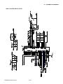
Data Controller Board...................................................................................... 12-1
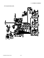
CIS Controller Board ..................................................................................... 12-16
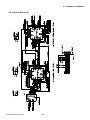
Data Power Board .......................................................................................... 12-20
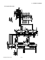
CIS Power Board ............................................................................................ 12-22
Relay Board .................................................................................................... 12-23
CS300/400-UM-251-9370
iii
12.6 IEEE 1394a Board .......................................................................................... 12-24
13. OPTION ............................................................................................... 13-1
13.1 Optional Items .................................................................................................. 13-1
13.2 Consumables ................................................................................................... 13-1
14. PARTS LIST ........................................................................................ 14-1
14.1
14.2
14.3
14.4
14.5
14.6
14.7
14.8
14.9
Outer Casing .................................................................................................... 14-1
Main Frame ....................................................................................................... 14-2
Front Guide .......................................................................................................14-4
Drive Roller .......................................................................................................14-6
CIS Unit .............................................................................................................14-8
Center Cover .................................................................................................. 14-10
Hold-down Unit .............................................................................................. 14-12
Cables ............................................................................................................. 14-14
Other Parts ..................................................................................................... 14-14
CS300/400-UM-251-9370
iv
1. OVERVIEW
1.
OVERVIEW
1.1 Features
• 600-dpi optical resolution for high-precision image scanning
Scanning with an optical resolution of 600 dpi allows even complex and difficult-to-scan documents,
such as CAD drawings, electronic files, and mapping data to be scanned rapidly and with high precision.
Scanning Master 21+ (scanner software included as a standard accessory) can be used to adjust the
resolution in five levels (50 dpi to 800 dpi, in 1-dpi increments) to suit the scanned document.
• Compatible document widths range from 210 mm to 1016 mm
Compatible with document sizes from ISO A4 up to ANSI E
• Capable of color and grayscale scanning
Capable of scanning in color (24-bit color*, 8-bit color) or grayscale (256 shades)
* CS400 only
• Capable of reading long-axis data
Scanning of long-axis images is supported.
• Compact and lightweight design
A compact design was achieved by using a document travel system that employs contact image sensors
in the sensor unit (five rows arranged in a zigzag pattern).
• Image-processing functions
Use of the scanning software provided lets you set image-processing functions for the scanning of a
document.
• Interface
USB 2.0, IEEE 1394
CS300/400-UM-251-9370
1-1
1. OVERVIEW
1.2 Standard Specifications
Item
CS400
CS400
Document size
ANSI E to ISO A4
Maximum width: 1090 mm; minimum width: 210 mm
Effective scanning
area
Width : 1016 mm (centered)
Length : 16 m*1
Guaranteed scanning
precision range*3
841 mm x 1189 mm
Document thickness
1.5 mm or less (including the carrier sheet)
Optical resolution
600 dpi
Interpolated resolution
50 to 800 dpi, in 1-dpi increments
Main scanning system
Contact image sensor system (Five A4 sensors in a zigzag pattern)
Sub scanning system
Document travel (sheet through) system
Scanning
speed*2
Monochrome: Approx. 0.55 ms/line
9 inch/s at 400 dpi
Color: Approx. 1.65 ms/line
3 inch/s at 400 dpi
Scanning precision*3
±0.1%, ±5 pixels
Gradation
Monochrome: Bilevel, intermediate tones (dithering, error diffusion)
Gray : 256 shades
Color: 8-bit, 24-bit
8-bit
Threshold value
Digital signal processor enable automatic setting of the threshold value
(monochrome scans only)
Color space
sRGB compatible
Light source
LED (RGB)
Interface*3
USB 2.0, IEEE 1394
Output
Image data
Rated power supply
100 to 120/200 to 240 VAC ±10%, 50/60 Hz
Operating environment
Temperature: 10˚C to 35˚C
Humidity: 35% to 80% RH (no condensation)
Power consumption
135 VA or less (60 W or less)
External dimensions
(approx.)
1205 X 957 X 715 mm (WXHXD) (including stand)
Weight
Approx. 40 kg (including stand)
* 1 Documents up to approximately 16 m in length (driver software limitation) can be scanned. However, the actual
document length that can be scanned is limited by the available memory (hard disk or other data storage device)
of the computer to which the scanner is connected, and also by the grade of the medium being scanned.
2
* Excluding data-transfer time
* 3 Notes on scanning precision
Scanning precision may vary slightly depending on the grade and thickness of the medium being scanned, and on
the operating conditions. The precision figures above were measured under the operating conditions described
below.
• Test chart used
: Mylar sheet #200
• Guaranteed precision conditions
: Temperature 20 ±3˚C; humidity: 60% ±10% RH
• Document hold-down unit setting
: Standard
* 4 The USB 2.0 and IEEE 1394 interface cannot be used at the same time.
CS300/400-UM-251-9370
1-2
1. OVERVIEW
1.3 External View
957
External Dimensions
715
1205
Unit
: mm
Dimensional precision error : ±5 mm
Note: The diagrams are of the CS400 model.
CS300/400-UM-251-9370
1-3
2. PART NAMES AND FUNCTIONS
2.
PART NAMES AND FUNCTIONS
2.1 Part Names and Functions
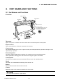
Front View
Paper sensor
Control panel
Top cover
Cover sensor
Document guides
* The CS300 document guides are
the magnetic guides supplied
as standard accessories.
Lock
Basket
Stand
Release
Caster
Top cover
Open the top cover to clean the document hold-down unit and transparent contact plates.
Paper sensors
These sense whether a document is present in the scanner.
Cover sensor
This senses whether the top cover is open or closed, and interrupts scanner operation if the top cover is
opened during operation.
Document guides
Use these guides to determine the position of a document when you load the document.
These guides are a sliding type for the CS400 and a magnetic type for the CS300.
Control panel
Use the keys to operate the scanner and the LEDs to monitor the operating status.
Stand
The stand unit is assembled for mounting of the scanner unit.
Basket
Receives the document that has been scanned.
Casters
Release the lock on the casters to allow the unit to be moved.
Do not touch the cover sensor or paper sensor.
CS300/400-UM-251-9370
2-1
2. PART NAMES AND FUNCTIONS
Front View
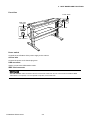
Power switch
IEEE 1394
connector
AC line inlet
USB connector
Power switch
Controls the on/off status of the power supply to the scanner.
AC line inlet
Connect the power cord’s female plug here.
USB connector
Used to connect the USB interface cable.
IEEE 1394 connector
The USB and IEEE 1394 connectors cannot be used at the same time. Do not connect both the USB and IEEE
1394 cables to a computer, or to two separate computers, at the same time.
CS300/400-UM-251-9370
2-2
2. PART NAMES AND FUNCTIONS
Control panel
POWER
PAPER
ERROR
SCAN
POWER LED
Unlit
Lit (green)
: Is unlit while the scanner is turned off.
: Lights when the scanner is turned and remains lit while it is operating
normally.
Flashing (orange) : Flashes when the scanner is in power-saving mode.
PAPER LED
FORWARD
REVERSE
STOP
Unlit
: Normal status (Local status).
Lit (green)
: Lights when the scanner enters Scan READY status.
Flashing (green) : Flashes while image data is being scanned.
ERROR LED
Lit (red)
Flashing (red)
: Lights to indicate a hardware error.
: Flashes when a document is detected during the selftest when the
scanner is turned on; when scanning is suspended by pressing the
STOP key; when a paper jam is detected; or when the document
length is shorter than the specified scan length.*
Unlit
: Normal status
(* When "Confirm" has been selected for the End-of-paper Processing setting in the
Scanning Master 21+ driver.)
SCAN key
This key enables you to scan a document according to the settings of Scanning Master
21+ when the scanner is connected to a computer.
Start up Scanning Master 21+ before scanning a document if it is not already active.
FORWARD key
Advances the document into the scanner. When this key is pressed in Scan READY
status, the Scan READY status is cancelled and the document is ejected toward the rear
of the scanner.
REVERSE key
Feeds the document toward you. When this key is pressed in Scan READY status, the
Scan READY status is cancelled and the document is ejected toward the front of the
scanner.
STOP key
Compulsorily stops scanning of the document.
CS300/400-UM-251-9370
2-3
3. PREPARING TO OPERATE THE SCANNER
3.
PREPARING TO OPERATE THE SCANNER
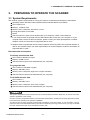
3.1 System Requirements
The minimum system requirements for running the scanner’s hardware and software are listed below.
Operating system: Windows 2000 Professional/XP Professional/9XP Home Edition
CPU: Pentium III/4
Memory: 32 MB or more
Monitor: 1024 × 768 pixels, 256 colors or more
Enough disk space to store data
Mouse
USB 2.0 interface*1 (that comes standard with your computer) or IEEE 1394 interface*2
*1 If your scanner does not operate with the USB interface that comes with your computer, or if your
computer does not have a USB 2.0 interface, please contact your sales representative or nearest
Graphtec vendor for information on supported add-on cards.
*2 Graphtec does not guarantee correct scanner operation with every IEEE 1394 computer interface or
add-on card. Please contact your sales representative or nearest Graphtec vendor for information on
supported add-on cards.
Recommended environment
For binary monochrome data
CPU: Pentium 200 MHz or higher
Memory: 64 MB or more
USB 2.0 interface (that comes standard with your computer)
For grayscale data
CPU: Pentium III 550 MHz or higher
Memory: 256 MB or more
Monitor: 1024 × 768 pixels, High Color or higher resolution
USB 2.0 interface (that comes standard with your computer)
For 8-bit/24-bit color data
CPU: Pentium 4
Memory: 512 MB or more
Monitor: 1024 × 768 pixels, True Color or higher
USB 2.0 interface (that comes standard with your computer)
The system configuration should correspond to the recommended specifications listed here, in order to ensure the
optimum capabilities of the scanner.
Use with a system configuration below the recommended specifications will affect the scanning speed and prevent
the scanner from operating to its specified capabilities.
To edit an A1-size or larger grayscale document with a resolution of 400 dpi or higher, or color document, you may
need more than the recommended memory sizes above. Depending on the type of document, you may not be able
to scan in the document even if you increase the memory size.
CS300/400-UM-251-9370
3-1
3. PREPARING TO OPERATE THE SCANNER
3.2 Connecting the Scanner to a Power Supply
Insert the female plug of the power cord provided into the scanner’s AC line inlet and insert its male plug into
an electrical socket supplying AC voltage.
Check that the scanner’s Power switch remains in the Off position until the connection of the power cord has
been completed.
Ensure that the scanner’s Power switch is in the Off position.
Make sure that your scanner is properly grounded. If it is not grounded, there is a possibility that noise
will cause incorrect operation, or that the scanned image may be distorted.
CS300/400-UM-251-9370
3-2
3. PREPARING TO OPERATE THE SCANNER
Turning the Scanner On or Off
Whenever the scanner's Power switch is turned on, the POWER, PAPER, and ERROR lamps on the control
panel light up. When the scanner has been initialized, the POWER lamp lights up.
When resetting the scanner by turning it off then back on again, wait at least five seconds before turning it back on.
CS300/400-UM-251-9370
3-3
3. PREPARING TO OPERATE THE SCANNER
3.3 Connecting the Scanner to a Computer
The scanner can be connected to a computer using the USB interface or IEEE 1394 interface.
The operation of the scanner cannot be guaranteed in the following cases:
• When the cable is connected to a USB hub or an add-on USB board.
• When you are using a custom-built computer or one that you have modified.
The following should never be attempted:
• Remove or reinsert the cable while you are installing the driver.
• Remove or reinsert the cable while starting up the computer or the scanner.
• Remove or reinsert the cable within a period of 5 seconds.
• Remove or reinsert the cable while transferring data.
• Connect two or more scanners to a single computer.
The USB and IEEE 1394 connectors cannot be used at the same time. Do not connect both the USB and IEEE
1394 cables to a computer, or to two separate computers, at the same time.
Connecting the scanner via a USB 2.0 interface
(1) Ensure that you have a USB 2.0 interface cable that works with your computer. Plug the USB 2.0
interface cable into the USB connector socket situated on the right-hand side of the scanner unit.
USB connector
To the computer
USB 2.0
CS300/400-UM-251-9370
3-4
3. PREPARING TO OPERATE THE SCANNER
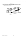
Connecting the scanner via an IEEE 1394 interface
(1) Ensure that you have an IEEE 1394 interface cable that works with your computer.
Plug the IEEE 1394 interface cable (6-pin) into the IEEE 1394 connector socket situated on the
right-hand side of the scanner unit.
IEEE 1394
connector
IEEE 1394 (6-pin)
connector
CS300/400-UM-251-9370
IEEE 1394
interface cable
3-5
To the computer
3. PREPARING TO OPERATE THE SCANNER
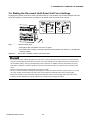
3.4 Making the Document Hold-Down Unit Force Settings
Changing the position of the lever at the right side of the top cover enables you to switch between two holddown force settings. Use this facility according to the status of the document to be scanned.
Standard
High
High .............. Use this setting with:
• Plain paper with a thickness of 0.8 mm or higher
• Documents with creases or strongly curled documents where the creases or curl affect the
scanning quality
Standard ...... This mode is normally used to scan a document.
• Do not use the “High” setting with paper less than 0.8 mm thick or with fine or limp documents, as the document
may become damaged or jammed in the scanner. The “High” setting has a stronger hold-down force than that of
the “Standard” setting, and may cause damage to thin documents. In addition, because the precision accuracy
also differs, a distance correction operation may need to be performed when you switch from one setting to the
other.
• Use the carrier sheet when scanning film documents or similar.
• Be sure to use the “Standard” setting with photographs or other documents that have a glossy surface. If you use
the “High” setting, the document may stick to the scanner glass and adversely affect the scanning quality.
• Always ensure that you check the lever status before using the scanner, because the modes may switch if the
scanner has been subjected to a strong vibration as a result of being dropped or shaken.
CS300/400-UM-251-9370
3-6
4. INSTALLING THE SOFTWARE
4.
INSTALLING THE SOFTWARE
The procedure outlined below is based on the requirement that you are logged on to Windows with administrator
rights. Consult your Windows 2000 or Windows XP manual for more information.
4.1
Installing the Driver Software for Windows 2000
The following procedure assumes that you are using the CS400 as part of your system, and that you are
using the USB interface. If you are using the IEEE 1394 interface, GRAPHTEC CS400-10 IEEE 1394 SBP2
Device will be displayed where CS400-10 is displayed when the USB interface is used. Substitute CS300-10
for CS400-10 for guidelines as to how to use the CS300.
(1) Connect the scanner to the computer, and turn on the computerʼs power. Insert the CD-ROM disk
(included with your computer) into the CD-ROM drive of the computer after Windows has started up,
and then turn on the scannerʼs power.
(2) The message below appears.
(3) Next, the Found New Hardware Wizard appears.
(4) Click the Next button to proceed to the menu for installing the driver.
CS300/400-UM-251-9370
4-1
4. INSTALLING THE SOFTWARE
(5) Select the option “Search for a suitable driver for my device (recommended)” and click Next.
(6) Select the check box entitled “Specify a location” and click Next.
Click Browse and select the DRIVER folder in the CD-ROM drive or enter a CD-ROM drive name and
\DRIVER using the keyboard.
Example: For drive E, enter “E:\DRIVER.”
(7) When you click OK the wizard will start searching for the driver. The screen shown below is displayed
when the wizard has finished searching.
CS300/400-UM-251-9370
4-2
4. INSTALLING THE SOFTWARE
(8) The screen shown below is displayed when you click Next.
Click Yes to continue the installation.
(9) The screen shown below is displayed when the wizard has finished installing the driver.
Click the Finish button.
(10) The Windows 2000 Desktop appears and the Scanner is acknowledged by the computer.
CS300/400-UM-251-9370
4-3
4. INSTALLING THE SOFTWARE
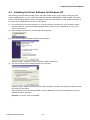
4.2 Installing the Driver Software for Windows XP
The following procedure assumes that you are using the CS400 as part of your system, and that you are
using the USB interface. If you are using the IEEE 1394 interface, GRAPHTEC CS400-10 IEEE 1394 SBP2
Device will be displayed where CS400-10 is displayed when the USB interface is used. Substitute CS300-10
for CS400-10 for guidelines as to how to use the CS300.
(1) Connect the scanner to the computer, turn on the scanner first, and then turn on the computer. When
Windows starts up, insert the CD-ROM supplied with the scanner in the CD-ROM drive. Turn on the
power to the scanner.
(2) When Windows XP starts up, the following window appears.
(3) Next, the Found New Hardware Wizard window appears.
Select the option “Install from a list or a specific location (Advanced)”.
(4) The screen shown below is displayed when you click Next.
Select the option “Search for the best driver in these locations” and select the check box entitled “Include
this location in the search”.
Click Browse and select the DRIVER folder in the CD-ROM drive or enter a CD-ROM drive name and
\DRIVER using the keyboard.
Example: For drive E, enter “E:\DRIVER.”
CS300/400-UM-251-9370
4-4
4. INSTALLING THE SOFTWARE
(5) When you click Next the wizard will start searching for the driver.
(6) The screen shown below is displayed.
Click Continue Anyway to continue the installation.
(7) The screen shown below is displayed when the wizard has finished installing the driver.
Click the Finish button to close the “Welcome to the Found New Hardware” wizard.
(8) The Windows XP desktop appears, and the scanner is recognized by the computer.
CS300/400-UM-251-9370
4-5
4. INSTALLING THE SOFTWARE
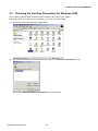
4.3
Checking the Interface Connection for Windows 2000
The procedure outlined below assumes that the CS400 is connected in your system.
Substitute CS300-10 for CS400-10 for guidelines as to how to use the CS300.
(1) Launch the Control Panel using the Start menu.
(2) The screen shown below is displayed when you click on the “Scanners and Cameras” icon.
Ensure that “Graphtec CS400-10 or CS300-10” is indicated here.
CS300/400-UM-251-9370
4-6
4. INSTALLING THE SOFTWARE
4.4 Checking the Interface Connection for Windows XP
The procedure outlined below assumes that the CS400 is connected in your system.
Substitute CS300-10 for CS400-10 for guidelines as to how to use the CS300.
(1) Launch the Control Panel using the Start menu.
(2) The screen shown below is displayed when you click on the “Printers and Other Hardware” icon.
(3) The screen shown below is displayed when you click on the “Scanners and Cameras” icon.
Ensure that “Graphtec CS400-10” or “Graphtec CS300-10” is indicated here.
CS300/400-UM-251-9370
4-7
4. INSTALLING THE SOFTWARE
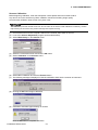
4.5 Installing the Scanning Master 21+ Application
The Scanning Master 21+ “OPS112” is a software application for using a Graphtec scanner to scan image
data.
Operating Environment
Windows 2000 Professional/XP Professional/XP Home Edition
Installation Procedure
(The following steps are explained using the Windows 2000 windows.)
(1) Boot Windows 2000.
(2) Insert the User Guide CD-ROM containing the OPS112 program files into the computer’s CD-ROM
drive.
(3) Click the Taskbar’s Start button, then click the Run... icon.
(4) Enter the CD-ROM drive name and English\OPS112\SETUP.EXE as the name of the file you wish to
open.
If the disk is in drive E, for example, enter “E:\English\OPS112\SETUP.EXE” in the box.
(5) Click the OK button to run the OPS112 setup program. From this point on, follow the setup programʼs
instructions to install the OPS112 application.
• If the application has been properly installed, “Scanning Master 21+” will be newly listed in the Program
menu accessed from the Start button.
For more details, open the README.TXT file provided in the “Scanning Master 21+” folder.
CS300/400-UM-251-9370
4-8
5. DAILY MAINTENANCE
5.
DAILY MAINTENANCE
5.1 Opening and Closing the Top Cover
(1) Turn off the scanner’s power.
(2) Push the left and right open levers on the top cover to unlock them, and hold the middle part of the top
cover while you open the top cover by about 90 degrees.
Open levers
Top cover
(3) Close the top cover until the left and right latches on the top cover lock into position, making sure that you
don’t get your fingers caught.
CS300/400-UM-251-9370
5-1
5. DAILY MAINTENANCE
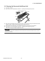
5.2 Cleaning the Document Hold-Down Unit
(1) Turn off the scanner.
(2) Open the top cover as described in Section 5.1 “Opening and Closing the Top Cover”.
Document hold-down unit
Latch
Latch
(3) Wipe clean the underside of the document hold-down unit (see below) using a soft cloth that has been
soaked in water or diluted neutral detergent and thoroughly wrung out.
(4) Wipe the document hold-down unit once again using a soft, dry cloth (remove all moisture).
(5) Close the top cover as described in Section 5.1 “Opening and Closing the Top Cover”.
Take care not to get your fingers caught in the cover.
Scanning may be affected if the underside of the document hold-down unit becomes scratched or dirty. It must be
cleaned when necessary.
CS300/400-UM-251-9370
5-2
5. DAILY MAINTENANCE
5.3 Cleaning the Image Sensors
The scanner’s image quality drops when the transparent contact plates over the image sensors become dirty,
so clean the image sensors whenever necessary.
Procedure
(1) Turn off the scanner.
(2) Open the top cover as described in Section 5.1 “Opening and Closing the Top Cover”.
(3) As shown below, wipe off any soiled areas on the transparent contact plates using a soft cloth that has
been moistened with water or a neutral detergent (diluted with water) and firmly wrung out.
Transparent contact plates
(4) Completely remove any moisture on the transparent contact plates by wiping them off again using a
soft, dry cloth.
(5) Close the top cover as described in Section 5.1 “Opening and Closing the Top Cover”.
Take care not to get your fingers caught in the cover.
Do not use a commercial cleaner for office equipment, a glass cleaner, or chemical solvents such as solutions containing alcohol.
Although the glass scanning table is not a maintenance part that requires periodic replacement, it is a consumable
part because its surface may receive slight scratches due to minute particles of dust and other foreign matter. If
document scanning produces unsatisfactory results (unexpected white or black streaks in the data) due to scratches on the glass table or other reasons, please perform the calibration procedure (see Section 5.4, “1. Calibration”).
If the scanning results do not improve after calibration, the glass table will need to be replaced.
CS300/400-UM-251-9370
5-3
5. DAILY MAINTENANCE
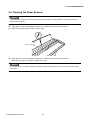
5.4 Cleaning the Paper Sensors
Accumulated dust on the paper sensors may prevent the document from being detected. The sensors must be
cleaned when necessary.
(1) Turn off the scanner.
(2) Open the top cover as described in Section 5.1 “Opening and Closing the Top Cover”.
(3) Wipe the two paper sensors using a cotton swab.
Paper sensors
(4) Close the top cover as described in Section 5.1 “Opening and Closing the Top Cover”.
Take care not to get your fingers caught in the cover.
Use a cotton swab or something equally soft to gently wipe the paper sensors. Do not use any chemicals to clean
the sensors.
CS300/400-UM-251-9370
5-4
5. DAILY MAINTENANCE
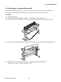
5.5 Removing a Jammed Document
If a document becomes jammed in the scanner during scanning or another operation, immediately turn off
the scanner, remove the document hold-down unit, and then remove the jammed document.
Procedure
(1) Turn off the scanner.
(2) Open the top cover as described in Section 5.1 “Opening and Closing the Top Cover”.
(3) If the document is jammed at the front, remove the document from the inside or by pulling it forward.
(4) If the document is jammed at the rear, remove the document from the inside by pulling it toward the rear.
(5) Close the top cover as described in Section 5.1 “Opening and Closing the Top Cover”.
Take care not to get your fingers caught in the cover.
CS300/400-UM-251-9370
5-5
5. DAILY MAINTENANCE
5.6 Calibration
Calibrate the scanner if scanning quality is observed to deteriorate, with scanned results such as those
described below:
• The scanned image is distorted
• Areas of uneven color appear in the scanned image
• Other unsatisfactory results (but not including problems related to media quality, such as folds, wrinkling, or
paper curling)
• Handle the calibration sheet with care so that it does not get bent. To prevent soiling, store it in its special storage
box. The calibration sheet cannot be used if it is bent or soiled.
• The calibration sheet is a paper product. Do not attempt to clean it with any type of liquid cleaner.
• The calibration sheet is a consumable item. Replacement sheets can be purchased from your sales representative
or nearest Graphtec vendor.
Preparation and checks
Recommended usage environment
• Monitor: 1024 x 768 pixels, High Color or better resolution
A low-resolution monitor will make it difficult to discern any problem areas.
Launching the Scanner Adjustment Program
(1)
(2)
(3)
(4)
Connect the scanner to the PC and switch on the scanner. Switch on the PC.
Install Scanning Master 21+ (OPS112) if it is not already installed.
Click the Start button, then select Programs > Scanning Master 21+ > Scanner Adjustment.
Click Scanner Adjustment to launch the Scanner Adjustment program.
CS300/400-UM-251-9370
5-6
5. DAILY MAINTENANCE
Scanner Calibration
Before beginning calibration, clean the transparent contact plates and scanner table surface.
Any dust or dirt on this surface may affect calibration results and resulting image quality.
Check that the calibration sheet is free of any dust or dirt.
The calibration procedure will take some time. Do not switch off the scanner while calibration is underway. Accidentally switching off the scanner may result in damage that requires servicing.
(1) Connect the scanner to the computer. Switch on the scanner, then switch on the PC.
(2) Launch the Scanner Adjustment program (as described earlier).
(3) Select Model Setup on the Scanner menu.
(4) Select the connected scanner and click the OK button.
(5) Select Calibration on the Scanner menu.
(6) Select All in Calibration and click the Execute button.
(7) The following message is displayed. Insert the calibration sheet into the scanner as instructed.
(8) Clicking the OK button begins calibration.
(9) Calibration ends after approximately 10 minutes.
Click the OK button to complete calibration.
CS300/400-UM-251-9370
5-7
5. DAILY MAINTENANCE
(10) To check the calibration results, click the Confirm button in the Calibration menu (shown in step (5)
above).
(11) The following message is displayed. Insert the calibration sheet into the scanner as instructed.
(12) Click the OK button to start scanning.
The scanned data is displayed when scanning is complete. Colors may differ slightly for individual
sensors to make it easier to identify problem areas in calibration. This does not indicate a defect.
Check that there are no vertical streaks, such as white patches, in the scanned data.
(Streaks occur when calibration is not performed correctly due to contamination by dust or dirt.)
(13) If the data is normal, calibration is complete.
Click the Close button and exit the Scanner Adjustment Program.
(14) If any abnormal data is observed, specify the problem areas as follows:
Select Specified Part in Calibration.
(15) The mouse arrow cursor changes to a cross cursor when moved over the data. Click the left mouse
button with the mouse positioned over the streak data. The selected area is shown in blue. Repeat this
procedure for any additional streaks.
Areas that have been selected (shown in blue) can be deselected by clicking the left mouse button
again. To deselect all selected areas, click the Clear button.
(16) Once all required areas have been specified, remove the calibration sheet and clean the glass and table
surfaces. Check the calibration sheet for dust and dirt, then click the Execute button.
(17) Return to step (10) and verify the calibration results.
CS300/400-UM-251-9370
5-8
5. DAILY MAINTENANCE
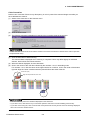
Color Correction
Perform color correction if there is any discrepancy in color in parts of the scanned image even after you
have calibrated the scanner.
(1) Select Color Correction on the Scanner menu.
(2) Click the Scan button.
(3) The following message is displayed. Insert the color correction sheet in the scanner.
Position the color correction sheet so that the red bar in the center of the sheet is centered in the scanner (but with
the printed side down).
(4) Click the OK button to start scanning.
The scanned data is displayed when scanning is complete. Colors may differ slightly for individual
sensors, but this does not indicate a defect.
(5) When the data is displayed, click the Get button.
(6) Click in the center of the color tile indicated by the numbers 1 to 6, in ascending order.
For numbers 1 to 5, click the center of the upper left tile; for number 6, click in the center of the bottom
right tile. Align the cursor crosshairs with the printed lines at the sides of the tile.
Cursor lines (red)
Align with the printed lines, then click.
• The next reference point to be checked is displayed on the Status bar.
• If you click in error, click the Esc. key to cancel the operation and return to the immediately previous step.
• If you click on the wrong tile, color correction will not be performed correctly and the colors of the image displayed
after color correction will be incorrect.
CS300/400-UM-251-9370
5-9
5. DAILY MAINTENANCE
(7) After you have clicked tile number 6, click the Set button.
Click the OK button.
(8) To check the color correction results, click the Confirm button.
(9) The following message is displayed. Insert the color correction sheet in the scanner as instructed.
Position the color correction sheet so that the red bar in the center of the sheet is centered in the scanner (but with
the printed side down).
(10) Click the OK button to start scanning.
After scanning has been completed, an enlarged view of the color-corrected data is displayed.
(11) Click the Fit icon to display the entire image, and check whether there is any discrepancy in color. If
there is no discrepancy, color correction is complete. Click the Close button.
If there is still some color discrepancy after performing Color Correction, repeat steps (6) through (11).
CS300/400-UM-251-9370
5-10
6. RECOMMENDED PARTS LIST
6.
No.
1
2
3
4
5
6
7
8
9
10
11
12
13
14
15
16
17
18
19
20
21
22
23
24
25
26
27
28
29
30
31
32
33
34
35
36
RECOMMENDED PARTS LIST
Part No.
774015500
774015501
774015502
774015503
774015504
774015505
694500780
694500790
694500800
694500811
694500830
694500840
694500850
694500860
694500870
694500880
500051795
500051794
308004002
641300000
500051793
502112009
502210002
502211000
694450052
500051630
314690020
341511001
378020021
774015027
641300130
641300633
641300100
641300110
641300050
641400050
Part Name
Data Controller Board
CIS Controller Board
Data Power Board
CIS Power Board
Motor Drive, 3-phase
IEEE 1394 Board
CIS Power Board Cable
Data Controller Board Power Cable
Motor Controller Board Power Cable
Motor (3-phase) Cable
Motor Controller Cable
Switching Power Board to Power Board Cable
Primary Power Cable
CIS Board to Data Board Cable
Sensor Cable
Inlet to Power Switch Cable
CIS Sensor
Motor
Motor Damper
Control Panel
Inlet
Power Switch
Paper Sensor
Cover Sensor
Fan
Switching Power Board
Bearing
O Ring
Drive Belt
Contact Glass 3mm
Drive Roller
Paper Hold-down Plate
Pinch Roller
Pinch Roller Shaft
Front Guide CS400
Front Guide CS300
CS300/400-UM-251-9370
6-1
Description
Q'ty
Remarks
1
5
1
1
1
1
3SB-2C-1
5
3SB-2C-2
1
3SB-2C-3
1
3SB-2C-4A
1
3SB-2C-6
1
3SB-2C-7
1
3SB-2C-8
1
3SB-2C-9
5
3SB-2C-10
1
3SB-2C-11
1
CIPS218CF601
5
KT60KM06-551
1
MOTOR MOUNT RF2600-A5 1
3SB CONTROL PANEL
1
FN-9222R-3-06
1
AJ7201B
1
PS-R50L-A
2
GP1A05A
1
CS2000C-6A
1
ZWS75AF-24/J
1
6900ZZNXR
4 SAME AS CS2000
1AP12
12 SAME AS CS2000
BELT 60S2M400
1
CONTACT GLASS 3mm
1
DRIVE ROLLER
2
CS-JEC
1 SAME AS CS2000
PINCH ROLLER G
4
SHAFT
1
FRONT GUIDE FOR CS400
1
FRONT GUIDE FOR CS300
1
7. LIST OF JIGS AND TOOLS
7.
LIST OF JIGS AND TOOLS
7.1 Jigs
Jigs
argos.X
OPS112 (Ver. 4.40 or later)
Adjustments
•Downloading system program
•Downloading system program
Remarks
Firmware (CS400/300.X)
Software supplied with the scanner
•Shading (white correction)
(Scanning Master 21+)
•Adjusting feed distance
•Aligning sensor images
•Adjusting offset
Calibration sheet
•Color correction
•Shading (white correction)
Color correction sheet
CS1000 adjustment test chart
•Replacing main board
•Color correction
•Adjusting feed distance
Standard accessory
1050 mm x 200 mm
Standard accessory
Record measured values between a and
•Adjusting offset
c, b and d, a and b, c and d, a and d, and
•Aligning sensor images
b and c.
Screwdriver
Usage
Disassembly, reassembly, and other
Remarks
Large, medium, and small flat blade
Allen wrench
operations
screwdrivers and Phillips screwdrivers
Needle-nose pliers
Colex gauge
Multimeter
Adjusting belt tension
Checking voltage level
200g / 4 mm displacement
7.2 Tools
Tools
7.3 Other
Item
Water-diluted neutral detergent or Cleaning
Usage
absolute ethanol wiper (cloth)
PC
Used to determine whether the problem
USB cable
is caused by the scanner or any other
equipment.
CS300/400-UM-251-9370
7-1
Remarks
8. DISASSEMBLING AND ADJUSTING THE MECHANICAL PARTS
8.
DISASSEMBLING AND ADJUSTING THE MECHANICAL PARTS
8.1 Right Side Cover
Detaching the right side cover
(1) Remove the three M4L6 binding head screws on the right side of the scanner unit.
(2) Detach the right side cover as shown below.
M4L6 Binding
Head Screw
J3
Right Side Cover
(3) Disconnect the connector J3 from the data power board.
Reattaching the right side cover
(1) Reattach the right side cover in the reverse order in which it was detached.
8.2 Left Side Cover
Detaching the left side cover
(1) Remove the three M4L6 binding head screws on the left side of the scanner unit.
(2) Detach the left side cover as shown below.
M4L6 Binding
Head Screw
Left Side Cover
Reattaching the left side cover
(1) Reattach the left side cover in the reverse order in which it was detached.
CS300/400-UM-251-9370
8-1
8. DISASSEMBLING AND ADJUSTING THE MECHANICAL PARTS
8.3 Center Cover Assembly
Detaching the center cover
(1) Detach the right and left side covers (see Sections 8.1 and 8.2).
(2) Remove the four M3L10 cap screws and the two M3L14 cap screws on both sides of the plate.
(3) Detach the center cover assembly from the scanner unit as shown below.
Center Cover
Assembly
M3L10 Cap
Screw
M3L10 Cap
Screw
M3L14 Cap
Screw
M3L14 Cap
Screw
Reattaching the top cover
(1) Reattach the top cover in the reverse order in which it was detached.
8.4 Front Guide Assembly
Detaching the front guide assembly
(1) Detach the right and left side covers (see Sections 8.1 and 8.2).
(2) Remove the four M3L6 binding head screws holding the front guide assembly from each side.
(3) Detach the front center guide assembly as shown below.
M3L6 Binding
Head Screw
M3L6 Binding
Head Screw
Front Guide Assembly
CS300 does not have this paper guide.
Reattaching the front guide assembly
(1) Reattach the front guide assembly in the reverse order in which it was detached.
When reattaching the front guide assembly, make sure that the front guide assembly does not touch the front drive
roller.
CS300/400-UM-251-9370
8-2
8. DISASSEMBLING AND ADJUSTING THE MECHANICAL PARTS
8.5 Rear Cover
Detaching the rear cover
(1) Remove the four M3L6 binding head screws at the back of the scanner unit.
M3L6 Binding Head Screw
(2) Detach the rear cover.
Reattaching the rear cover
(1) Reattach the rear cover in the reverse order in which it was detached.
When reattaching the rear cover, make sure that the rear cover does not touch the rear drive roller.
CS300/400-UM-251-9370
8-3
8. DISASSEMBLING AND ADJUSTING THE MECHANICAL PARTS
8.6 CIS Unit
Detaching the CIS unit
(1) Detach the right and left side covers (see Sections 8.1 and 8.2).
(2) Remove the four M4L12 binding head screws and the two bushes at the left side of the scanner unit as
shown below.
(3) Lift up the left side of the CIS unit and slide the CIS unit out to the left of the scanner unit.
(4) Disconnect the connectors from each CIS board.
(5) Detach the CIS unit.
Lift up this side first.
M4L12 Binding
Head Screw
Bush
4L6.5
Reattaching the bottom plates
(1) Reattach the CIS unit by reversing the sequence of steps in which it was detached.
Align the CIS unit with the side of the main unit when attaching the CIS unit.
Align the CIS unit with the rear of the
main unit when attaching the CIS unit
Front
CS300/400-UM-251-9370
8-4
8. DISASSEMBLING AND ADJUSTING THE MECHANICAL PARTS
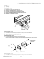
8.7 Motor
Detaching the motor
(1)
(2)
(3)
(4)
(5)
Detach the left side cover (see Section 8.2).
Detach the front guide assembly (see Section 8.4).
Disconnect the J4 connector from the data power board.
Remove the two M4L6 binding head screws holding the motor.
Detach the drive belt from the pulleys.
Belt
M4L6 binding
head screws
Reattaching the motor
(1) Reattach the motor by reversing the sequence of steps in which it was detached.
(2) Adjust the drive belt tension (see Section 8.10)
Disassembling the motor
(1) Loosen the M3L6WP set screws to detach the motor pulley.
Remove the two silver M4L12 binding head screws holding together the motor and motor mount.
M4L12 binding
head screw
M3L6WP set screw
Motor
Pulley
Motor mount
Reattaching the motor
(1) Reattach the motor by reversing the sequence of steps in which it was detached.
CS300/400-UM-251-9370
8-5
8. DISASSEMBLING AND ADJUSTING THE MECHANICAL PARTS
8.8 Drive Roller Pulley
Detaching the drive roller pulleys
(1) Detach the left side cover (see Section 8.2).
(2) Loosen the two M4L6 binding head screws holding the motor.
Belt
M4L6 binding
head screws
(3) Detach the drive belt from the pulleys.
(4) Loosen the M3L6WP set screw to detach the drive roller pulley
Drive roller pulley
Drive roller belt
M4L6WP set screw
Reattaching the drive roller pulleys
(1) Reattach the drive roller pulleys by reversing the sequence of steps in which they were detached.
(2) Adjust the belt tension (see Section 8.10)
CS300/400-UM-251-9370
8-6
8. DISASSEMBLING AND ADJUSTING THE MECHANICAL PARTS
8.9 Drive Rollers
Detaching the front drive roller
(1)
(2)
(3)
(4)
(5)
(6)
(7)
Detach the right and left side covers (see Sections 8.1 and 8.2).
Detach the front guide assembly (see Section 8.4).
Detach the drive roller belt and the pulley from the drive roller (see Section 8.8).
Detach the E-ring holding the drive roller.
Detach the two bearings holding both ends of the drive roller.
Remove the two M3L6 binding head screws holding the left side center cover sensor bracket.
Disconnect the left side center cover sensor cable from the connector and then detach the left side
center cover sensor together with the bracket.
(8) Slide the drive roller to the left, lift up the drive roller from the right side, and then detach it.
Front drive roller
Rear drive roller
Bearing
E-ring
Left side center
cover sensor bracket
M4L6 binding
head screw
Detaching the rear drive roller
(1)
(2)
(3)
(4)
(5)
(6)
Detach the right and left side covers (see Sections 8.1 and 8.2).
Detach the rear guide (see Section 8.5).
Detach the drive roller belt and the pulley from the drive roller (see Section 8.8).
Detach the E-ring holding the drive roller.
Detach the two bearings holding both ends of the drive roller.
Slide the drive roller to the left, lift up the drive roller from the right side, and then detach it.
Reattaching the drive rollers
(1) Reattach the drive rollers by reversing the sequence of steps in which they were detached.
(2) Adjust the drive belt tension (see Section 8.10)
CS300/400-UM-251-9370
8-7
8. DISASSEMBLING AND ADJUSTING THE MECHANICAL PARTS
8.10 Drive Belt
Detaching the drive belt
(1) Detach the left side cover (see Section 8.2).
(2) Loosen the two M4L6 binding head screws holding the motor.
(3) Detach the drive belt from the pulleys.
Belt
M4L6 binding
head screws
Reattaching the drive belt
(1) Reattach the drive belt by reversing the sequence of steps in which it was detached.
(2) Adjust the drive belt tension.
Adjusting the drive belt tension
(1) Loosen the two M4L6 binding head screws holding the motor.
(2) Pull the motor in the "A" direction as shown below.
(3) Use the Colex gauge to adjust the belt tension so that the belt displacement is approximately 1.6 mm
when pressed with a force of 167 gf.
167 g
1.6 mm
Belt
Drive roller pulley
A
M4L6 binding
head screws
Belt
Motor pulley
(4) Tighten the two M4L6 binding head screws holding the motor.
CS300/400-UM-251-9370
8-8
8. DISASSEMBLING AND ADJUSTING THE MECHANICAL PARTS
8.11 Center Cover Sensor
Detaching the left side center cover sensor
(1)
(2)
(3)
(4)
Detach the right and left side covers (see Sections 8.1 and 8.2).
Detach the front guide assembly (see Section 8.4).
Remove the two M3L6 binding head screws holding the left side center cover sensor bracket.
Disconnect the left side center cover sensor cable from the connector then detach the left side center
cover sensor together with the bracket.
(5) Remove the M4L6 binding head screw holding the left side center cover sensor.
M4L10 binding
head screw
Right side center
cover sensor
M3L6 binding
head screw
Right side center
cover sensor bracket
Rear paper
detection sensor
M3L10 binding
head screw
M4L6 binding
head screw
Left side center
cover sensor bracket
M3L10 binding
head screw
Left side center
cover sensor
Front paper
detection sensor
M3L6 binding
head screw
Detaching the right side center cover sensor
(1)
(2)
(3)
(4)
(5)
(6)
Detach the right and left side covers (see Sections 8.1 and 8.2).
Detach the front guide assembly (see Section 8.4).
Disconnect the right side center cover sensor cable from the connector.
Remove the M3L6 binding head screw holding the right side center cover sensor bracket.
Detach the right side center cover sensor together with the bracket.
Remove the M4L10 binding head screw holding the right side center cover sensor.
Reattaching the center cover sensors
(1) Reattach the center cover sensors by reversing the sequence of steps in which they were detached.
CS300/400-UM-251-9370
8-9
8. DISASSEMBLING AND ADJUSTING THE MECHANICAL PARTS
8.12 Front and Rear Paper Detection Sensors
Detaching the front paper detection sensor
(1)
(2)
(3)
(4)
Detach the right and left side covers (see Sections 8.1 and 8.2).
Detach the front guide assembly (see Section 8.4).
Remove the M3L10 binding head screws holding the front paper detection sensor.
Disconnect the front paper detection sensor cable from the connector and then detach the front paper
detection sensor.
M4L10 binding
head screw
Right side center
cover sensor
M3L6 binding
head screw
Right side center
cover sensor bracket
Rear paper
detection sensor
M3L10 binding
head screw
M4L6 binding
head screw
Left side center
cover sensor bracket
M3L10 binding
head screw
Left side center
cover sensor
Front paper
detection sensor
M3L6 binding
head screw
Detaching the rear paper detection sensor
(1) Detach the rear guide (see Section 8.5).
(2) Remove the M3L10 binding head screws holding the rear paper detection sensor.
(3) Disconnect the rear paper detection sensor cable from the connector and then detach the rear paper
detection sensor.
Reattaching the paper detection sensors
(1) Reattach the paper detection sensors by reversing the sequence of steps in which they were detached.
CS300/400-UM-251-9370
8-10
8. DISASSEMBLING AND ADJUSTING THE MECHANICAL PARTS
8.13 Control Panel Sheet Switch
Detaching the control panel sheet switch
(1) Detach the right cover (see Section 8.1).
(2) Disconnect the flexible cable from the control panel relay board and then pull off the control panel sheet
switch from the right side cover.
Flexible Cable
Reattaching the control panel sheet switch
(1) Reattach the new control panel switch in the reverse order in which it was detached.
CS300/400-UM-251-9370
8-11
8. DISASSEMBLING AND ADJUSTING THE MECHANICAL PARTS
8.14 Contact Glass Assembly
Detaching the contact glass assembly
(1) Open the center cover.
(2) Remove the six M2L5 binding head screws holding the front contact glass stopper plate.
M2L5 binding head screw
M2L5 binding head screw
(3)
(4)
(5)
(6)
Detach the front contact glass stopper plate from the unit.
Remove the six M2L5 binding head screws holding the rear contact glass stopper plate.
Detach the rear contact glass stopper plate from the unit.
Slide the contact glass assembly to the right side, lift up the contact glass from the left side, and then
detach the contact glass assembly from the unit.
Reattaching the contact glass assembly
(1) Reattach the contact glass in the reverse order in which it was detached.
(2) Make sure that each of the CIS assembly surfaces lies flat against the inside of the contact glass
assembly when you reattach the contact glass assembly.
(3) Perform the software adjustment.
When replacing the contact glass assembly, be sure to clean the interior of the image sensor unit and the inside of
the contact glass assembly. A soiled or dusty unit can affect scanning performance.
CS300/400-UM-251-9370
8-12
8. DISASSEMBLING AND ADJUSTING THE MECHANICAL PARTS
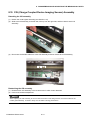
8.15 CIS (Charge Coupled Device Imaging Sensor) Assembly
Detaching the CIS assembly
(1) Detach the contact glass assembly (see Section 8.14).
(2) Slide each CIS assembly to the left side, lift it up from the right side, and then detach each CIS
assembly.
(3) Disconnect the flexible cable from each CIS assembly and then detach each CIS assembly.
Flexible cable
Reattaching the CIS assembly
(1) Reattach each CIS assembly in the reverse order in which it was detached.
(2) Perform the software adjustment.
When replacing the CIS assembly, be sure to clean the interior of the image sensor unit and the inside of the
contact glass assembly. A soiled or dusty unit can affect scanning performance.
CS300/400-UM-251-9370
8-13
8. DISASSEMBLING AND ADJUSTING THE MECHANICAL PARTS
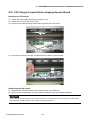
8.16 CIS (Charge Coupled Device Imaging Sensor) Board
Detaching the CIS boards
(1) Detach the contact glass assembly (see Section 8.14).
(2) Detach the each CIS (see Section 8.15).
(3) Remove the two M2L5 binding head screws supporting each CIS board.
CIS board
M2L5 binding head screw
(4) Disconnect the cables from each CIS board and then detach each CIS board.
Cable
Reattaching the CIS boards
(1) Reattach each CIS board in the reverse order in which it was detached.
(2) When you have replaced the CIS board, perform calibration using the software adjustment.
When replacing the CIS board, be sure to clean the interior of the image sensor unit and the inside of the contact
glass assembly. A soiled or dusty unit can affect scanning performance.
CS300/400-UM-251-9370
8-14
8. DISASSEMBLING AND ADJUSTING THE MECHANICAL PARTS
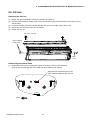
8.17 Document Hold-down Plate
Detaching the document hold-down plate
(1) Remove the two M3L6 binding head screws holding the front pinch roller cover.
M3L6 binding head screw
(2) Detach the front pinch roller cover from the center cover assembly.
(3) Remove the two M3L6 binding head screws holding the document hold-down assembly.
M3L6 binding head screw
M3L6 binding head screw
(4) Detach the document hold-down assembly from the center cover assembly.
CS300/400-UM-251-9370
8-15
8. DISASSEMBLING AND ADJUSTING THE MECHANICAL PARTS
(5) Remove the five M3L8 flat head screws holding the document hold-down plate and gently detach the
document hold-down plate to prevent the springs inside from coming out.
M3L6 binding head screw
Reattaching the document hold-down plate
(1) Reattach the document hold-down plate in the reverse order in which it was detached.
CS300/400-UM-251-9370
8-16
8. DISASSEMBLING AND ADJUSTING THE MECHANICAL PARTS
8.18 Pinch Roller Units
Detaching the front pinch roller units
(1) Remove the two M3L6 binding head screws holding both sides of the front pinch roller cover.
M3L6 binding head screw
(2) Detach the front pinch roller cover from the center cover assembly.
(3) Remove the two M3L6 binding head screws holding the four pinch rollers unit assembly.
M3L6 binding
head screw
M3L6 binding
head screw
M3L6 binding
head screw
(4) Remove the four M3L6 binding head screws holding the five pinch rollers unit assembly.
Detaching the rear pinch roller units
(1) Remove the four M3L6 binding head screws holding the rear of the rear pinch roller cover.
M3L6 binding
head screw
CS300/400-UM-251-9370
8-17
8. DISASSEMBLING AND ADJUSTING THE MECHANICAL PARTS
(2) Remove the two M3L6 binding head screws holding both sides of the rear pinch roller cover.
M3L6 binding head screw
(3) Detach the rear pinch roller cover from the center cover assembly.
(4) Remove the two M3L6 binding head screws holding the four pinch rollers unit assembly.
M3L6 binding
head screw
M3L6 binding
head screw
M3L6 binding
head screw
(5) Remove the four M3L6 binding head screws holding the five pinch rollers unit assembly.
Reattaching the pinch roller units
(1) Reattach the pinch roller units in the reverse order in which they were detached.
CS300/400-UM-251-9370
8-18
8. DISASSEMBLING AND ADJUSTING THE MECHANICAL PARTS
8.19 IEEE 1394 Board
Detaching the IEEE 1394 board
(1) Detach the right and left side covers (see Sections 8.1 and 8.2).
(2) Detach the front guide assembly (see Section 8.4).
(3) Remove the two M3L6 binding head screws and the one M2L6 binding head screw holding the IEEE
1394 board.
Switching power supply board
IEEE1394 board
CIS power board
Data controller board
Data power board
M3L6 binding head screw
M2L6 binding head screw
(4) Detach the IEEE 1394 board from the data controller board.
Reattaching the IEEE 1394 board
(1) Reattach the IEEE 1394 board in the reverse order in which it was detached.
(2) When replacing the IEEE 1394 board, perform the software adjustment to input the MAC address for
the IEEE 1394 board (See "Replacing the IEEE 1394 board" in Section 9.3).
CS300/400-UM-251-9370
8-19
8. DISASSEMBLING AND ADJUSTING THE MECHANICAL PARTS
8.20 Data Controller Board
When replacing the data controller board, perform the software adjustment to obtain the former setting values from
the data controller board.
Detaching the data controller board
(1)
(2)
(3)
(4)
Detach the right and left side covers (see Sections 8.1 and 8.2).
Detach the front guide assembly (see Section 8.4).
Detach the IEEE 1394 board (see Section 8.19).
Remove the two M3L6 flat head screws holding the USB cover and then detach the USB cover from the
unit.
M3L6 Flat head screw
(5) Disconnect all the connectors on the data controller board and remove the two M3L6 binding head
screws, the one M2 spacer and the two M3 spacers holding the data control board.
USB cover
M3L6
binding head
screw
M3 Spacer
M2 Spacer
(6) Detach the data controller board from the unit.
CS300/400-UM-251-9370
8-20
8. DISASSEMBLING AND ADJUSTING THE MECHANICAL PARTS
Reattaching the data controller board
(1) Reattach the data controller board in the reverse order in which it was detached.
(2) Set the DIP switch setting for each model (See "Replacing the Data Controller Board" in Section 9.2).
(3) Perform the software adjustment to input the former setting values or adjust the scanner by software
adjustment. (See "Preparations before Making Adjustment" in Section 10.2)
(4) When replacing the data controller board, write down the MAC address that is shown on the old data
controller board on the new data controller board.
When replacing the data controller board, perform the software adjustment to obtain the former setting values from
data controller board. (See "Preparations before Making Adjustment" in Section 10.2)
CS300/400-UM-251-9370
8-21
8. DISASSEMBLING AND ADJUSTING THE MECHANICAL PARTS
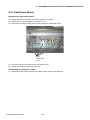
8.21 Data Power Board
Detaching the data power board
(1) Detach the right and left side covers (see Sections 8.1 and 8.2).
(2) Detach the front guide assembly (see Section 8.4).
(3) Remove the six M3L6 binding head screws holding the data power board.
M3L6
binding head
screw
(4) Disconnect all the connectors on the data power board.
(5) Detach the data power board from the unit.
Reattaching the data power board
(1) Reattach the data power board in the reverse order in which it was detached.
CS300/400-UM-251-9370
8-22
8. DISASSEMBLING AND ADJUSTING THE MECHANICAL PARTS
8.22 CIS Power Board
Detaching the CIS power board
(1) Detach the right and left side covers (see Sections 8.1 and 8.2).
(2) Detach the front guide assembly (see Section 8.4).
(3) Remove the four M3L6 binding head screws holding the CIS power board.
M3L6 binding head screw
(4) Disconnect all the connectors on the CIS power board.
(5) Detach the CIS power board from the unit.
Reattaching the CIS power board
(1) Reattach the CIS power board in the reverse order in which it was detached.
(2) Adjust the output voltage to 5.45V ±0.02V between pins 3 and 4 of J10 using VR1 on the CIS power
board when you replace any of the boards.
CS300/400-UM-251-9370
8-23
8. DISASSEMBLING AND ADJUSTING THE MECHANICAL PARTS
8.23 Switching Power Supply Board
Detaching the switching power supply board
(1) Detach the right and left side covers (see Sections 8.1 and 8.2).
(2) Detach the front guide assembly (see Section 8.4).
(3) Remove the four M3L6 binding head screws holding the switching power supply board.
M3L6 binding head screw
(4) Disconnect all the connectors on the switching power supply board.
(5) Detach the switching power supply board from the unit.
Reattaching the data power board
(1) Reattach the switching power supply board in the reverse order in which it was detached.
CS300/400-UM-251-9370
8-24
9. BOARDS AND ELECTRICAL COMPONENTS
9.
BOARDS AND ELECTRICAL COMPONENTS
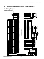
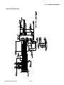
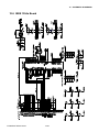
9.1 Wiring Diagrams
OPERATION PANEL
J31
52610-1090
3SB-2OPR
DF13B-11P-1.25V
USB2.0
TO PC
1
2
3
U 1
V 2
M 3
J4
1
2
3
4
J3
DF13-10P-1.25V
J6
B4P-VH
24V
24V
GND
GND
J5
DF13B-2P-1.25V
1 PD3
2 GND/G
3SB-2C-13
PD3
GND/G
PD3
GND/G
DATA POWER BOARD
3SB-2C-2
J2
B10B-PH-SM3-TB
1 5V
2 3.3V
3 3.3V
4 3.3V
5 3.3V
6 GND
7 GND
8 GND
9 GND
10 GND
1
2
3
4
J15
DF13B-4P-1.25V
1
2
3
4
CIS POWER BOARD
J1
B4P-VH
24V
24V
GND
GND
PD3 1
GND/G 2
3SB-2C-1C
J2
DF13B-2P-1.25V
3SB-2CPB
12V
GND
5V
GND
12V
GND
5V
GND
12V
GND
5V
GND
1
2
3
4
1
2
3
4
3SB-2C-9A
1
2
3
4
J10
J11
J13
J14
J12
DF13-4P-1.25V DF13-4P-1.25V DF13-4P-1.25V DF13-4P-1.25V DF13-4P-1.25V
12V
GND
5V
GND
1 +3.3V
2 +3.3V
3 GND
4 GND
5 MAIN CLOCK+
6 SHIFT CLOCK+
7 MAIN CLOCK8 SHIFT CLOCK9 SERIAL DATA+
10 DATA LATCH+
11 SERIAL DATA12 DATA LATCH13 LINK CLK O/P+
14 0CH DATA+
15 LINK CLK O/P16 0CH DATA17 1CH DATA+
18 1CH DATA19 RESET
20 GND
3SB-2C-6A
1
2
3
4
3SB-2CCB
+3.3V 1
+3.3V 2
GND 3
GND 4
MAIN CLOCK+ 5
SHIFT CLOCK+ 6
MAIN CLOCK- 7
SHIFT CLOCK- 8
SERIAL DATA+ 9
DATA LATCH+ 10
SERIAL DATA- 11
DATA LATCH- 12
LINK CLK O/P+ 13
0CH DATA+ 14
LINK CLK O/P- 15
0CH DATA- 16
1CH DATA+ 17
1CH DATA- 18
RESET 19
GND 20
J20
DF20F-20DP-1V(59)
J3
DF13B-4P-1.25V(21)
1 LEDG
2 LEDR
3 LEDB
4 LEDCA
5 GND
6 RS
7 GND
8 M
9 TR
10 VCC
11 GND
12 OS1
13 GND
14 OS2
15 GND
DF20F-20DP-1V(59)
1
2
3
4
5
6
7
8
9
10
11
12
13
14
15
J2
LEDG
LEDR
LEDB
LEDCA
GND
RS
GND
M
TR
VCC
GND
OS1
GND
OS2
GND
12V
GND
5V
GND
J1 FH10A-15S-1SH(02)
CIS SENSOR
1
2
3
4
CIS CONTROLLER BOARD
3SB-2C-9A
1 MTR PULS
2 MTR RESET
3 0
4 1
5 2
6 3
7 4
8 5
9 6
10 GND
12V
GND
5V
GND
1 +3.3V
2 +3.3V
3 GND
4 GND
5 MAIN CLOCK+
6 SHIFT CLOCK+
7 MAIN CLOCK8 SHIFT CLOCK9 SERIAL DATA+
10 DATA LATCH+
11 SERIAL DATA12 DATA LATCH13 LINK CLK O/P+
14 0CH DATA+
15 LINK CLK O/P16 0CH DATA17 1CH DATA+
18 1CH DATA19 RESET
20 GND
1
2
3
4
3SB-2CCB
1
2
3
4
5
6
7
8
9
10
11
12
13
14
15
16
17
1CH DATA- 18
RESET 19
GND 20
+3.3V
+3.3V
GND
GND
MAIN CLOCK+
SHIFT CLOCK+
MAIN CLOCKSHIFT CLOCKSERIAL DATA+
DATA LATCH+
SERIAL DATADATA LATCHLINK CLK O/P+
0CH DATA+
LINK CLK O/P0CH DATA1CH DATA+
J21
DF20F-20DP-1V(59)
J3
DF13B-4P-1.25V(21)
DF20F-20DP-1V(59)
1 LEDG
2 LEDR
3 LEDB
4 LEDCA
5 GND
6 RS
7 GND
8 M
9 TR
10 VCC
11 GND
12 OS1
13 GND
14 OS2
15 GND
J2
1
2
3
4
5
6
7
8
9
10
11
12
13
14
15
J1 FH10A-15S-1SH(02)
CIS SENSOR
LEDG
LEDR
LEDB
LEDCA
GND
RS
GND
M
TR
VCC
GND
OS1
GND
OS2
GND
12V
GND
5V
GND
CIS CONTROLLER BOARD
3SB-2C-9A
1
2
3
4
3SB-2C-1B
3SB-2C-1B
3SB-2C-1B
3SB-2C-1B
3SB-2C-1B
CS300/400-UM-251-9370
B3B-XH-A
24V
24V
GND
GND
J1
B4P-VH
1
2
3
4
3SB-2C-8
3SB-2C-4A
1
2
3
4
5
6
24V
24V
24V
GND
GND
GND
BRUSHLESS MOTOR
3SB-2C-8
STEPPING MOTOR
FG 1
2
AC 3
4
GND 5
AC100∼240V
IEEE1394
SWITCHING POWER SUPPLY
1
2
3
4
5
6
7
8
9
10
1
2
3
4
5
6
3SB-2IEEE
5V
3.3V
3.3V
3.3V
3.3V
GND
GND
GND
GND
GND
J2
53462
1
2
3
4
5
6
7
8
9
10
NC
NC
TPB*
TPB
TPA*
TPA
IEEE1394 BOARD
MTR_PULSE
MTR_RESET
0
1
2
3
4
5
6
GND
J10
FX8C-60S-SV5(22)
RELAY BOARD
J32
1 +3.3V
2 +3.3V
3 GND
4 GND
5 MAIN CLOCK+
6 SHIFT CLOCK+
7 MAIN CLOCK8 SHIFT CLOCK9 SERIAL DATA+
10 DATA LATCH+
11 SERIAL DATA12 DATA LATCH13 LINK CLK O/P+
14 0CH DATA+
15 LINK CLK O/P16 0CH DATA17 1CH DATA+
18 1CH DATA19 RESET
20 GND
STOP SW 1
REV SW 2
SW_GND 3
SCAN SW 4
FWD SW 5
LED_GND 6
ER_LD(RED) 7
PP_LD(GR) 8
PW_LD(OR) 9
PW_LD(GR) 10
3SB-2DPB
3SB-2CCB
+3.3V 1
+3.3V 2
GND 3
GND 4
MAIN CLOCK+ 5
SHIFT CLOCK+ 6
MAIN CLOCK- 7
SHIFT CLOCK- 8
SERIAL DATA+ 9
DATA LATCH+ 10
SERIAL DATA- 11
DATA LATCH- 12
LINK CLK O/P+ 13
0CH DATA+ 14
LINK CLK O/P- 15
0CH DATA- 16
1CH DATA+ 17
1CH DATA- 18
RESET 19
GND 20
J22
DF20F-20DP-1V(59)
J3
DF13B-4P-1.25V(21)
DF20F-20DP-1V(59)
1 LEDG
2 LEDR
3 LEDB
4 LEDCA
5 GND
6 RS
7 GND
8 M
9 TR
10 VCC
11 GND
12 OS1
13 GND
14 OS2
15 GND
J2
1
2
3
4
5
6
7
8
9
10
11
12
13
14
15
J1 FH10A-15S-1SH(02)
CIS SENSOR
LEDG
LEDR
LEDB
LEDCA
GND
RS
GND
M
TR
VCC
GND
OS1
GND
OS2
GND
12V
GND
5V
GND
CIS CONTROLLER BOARD
3SB-2C-9A
1
2
3
4
1 VCC/G
2 VCC/G
3 GND/G
4 GND/G
5 D<15>
6 D<14>
7 D<13>
8 D<12>
9 D<11>
10 D<10>
11 D<9>
12 D<8>
13 D<7>
14 D<6>
15 D<5>
16 D<4>
17 D<3>
18 D<2>
19 D<1>
20 D<0>
21 A<8>
22 A<7>
23 A<6>
24 A<5>
25 A<4>
26 A<3>
27 A<2>
28 A<1>
29 CS
30 WR<0>
31 RD
32 RESET
33 DACK
34 END_P
35 RESERVE0
36 RESERVE1
37 DREQ
38 INT
39 NC
40 IFSEL<0>
41 IFSEL<1>
42 IFSEL<2>
43 RESERVE2
44 NC
45 RESERVE3
46 NC
47 VCC/G
48 VCC/G
49 GND/G
50 GND/G
51 NC
52 NC
53 NC
54 NC
55 NC
56 NC
57 NC
58 NC
59 NC
60 NC
J1
FX8C-60P-SV6(22)
J3
DF13B-11P-1.25V
J11
UBR44-4N5C10
1
2
3
4
5
6
7
8
9
10
11
12
13
14
15
16
17
18
19
20
21
22
23
24
25
26
27
28
29
30
31
32
33
34
35
36
37
38
39
40
41
42
43
44
45
46
47
48
49
50
51
52
53
54
55
56
57
58
59
60
3SB-2DCB
1 +3.3V
2 +3.3V
3 GND
4 GND
5 MAIN CLOCK+
6 SHIFT CLOCK+
7 MAIN CLOCK8 SHIFT CLOCK9 SERIAL DATA+
10 DATA LATCH+
11 SERIAL DATA12 DATA LATCH13 LINK CLK O/P+
14 0CH DATA+
15 LINK CLK O/P16 0CH DATA17 1CH DATA+
18 1CH DATA19 RESET
20 GND
DATA CONTROLLER BOARD
3SB-2CCB
+3.3V 1
+3.3V 2
GND 3
GND 4
MAIN CLOCK+ 5
SHIFT CLOCK+ 6
MAIN CLOCK- 7
SHIFT CLOCK- 8
SERIAL DATA+ 9
DATA LATCH+ 10
SERIAL DATA- 11
DATA LATCH- 12
LINK CLK O/P+ 13
0CH DATA+ 14
LINK CLK O/P- 15
0CH DATA- 16
1CH DATA+ 17
1CH DATA- 18
RESET 19
GND 20
J23
DF20F-20DP-1V(59)
J3
DF13B-4P-1.25V(21)
DF20F-20DP-1V(59)
J2
FH10A-15S-1SH(02)
1 LEDG
2 LEDR
3 LEDB
4 LEDCA
5 GND
6 RS
7 GND
8 M
9 TR
10 VCC
11 GND
12 OS1
13 GND
14 OS2
15 GND
J1
M
TR
VCC
GND
OS1
GND
OS2
GND
1
2
3
4
5
6
7
8
9
10
11
12
13
14
15
CIS CONTROLLER BOARD
CIS SENSOR
LEDG
LEDR
LEDB
LEDCA
GND
RS
GND
12V
GND
5V
GND
1
2
3
4
VCC/G
VCC/G
GND/G
GND/G
D<15>
D<14>
D<13>
D<12>
D<11>
D<10>
D<9>
D<8>
D<7>
D<6>
D<5>
D<4>
D<3>
D<2>
D<1>
D<0>
A<8>
A<7>
A<6>
A<5>
A<4>
A<3>
A<2>
A<1>
CS
WR<0>
RD
RESET
DACK
END_P
RESERVE0
RESERVE1
DREQ
INT
NC
IFSEL<0>
IFSEL<1>
IFSEL<2>
RESERVE2
NC
RESERVE3
NC
VCC/G
VCC/G
GND/G
GND/G
NC
NC
NC
NC
NC
NC
NC
NC
NC
NC
3SB-2C-9A
1
2
3
4
1 STOP SW
2 REV SW
3 SW_GND
4 SCAN SW
5 FWD SW
6 LED_GND
7 ER_LD(RED)
8 PP_LD(GR)
9 PW_LD(OR)
10 PW_LD(GR)
11 NC
3SB-2C-6A
BOARD TO BOARD CONNECTOR
1 +3.3V
2 +3.3V
3 GND
4 GND
5 MAIN CLOCK+
6 SHIFT CLOCK+
7 MAIN CLOCK8 SHIFT CLOCK9 SERIAL DATA+
10 DATA LATCH+
11 SERIAL DATA12 DATA LATCH13 LINK CLK O/P+
14 0CH DATA+
15 LINK CLK O/P16 0CH DATA17 1CH DATA+
18 1CH DATA19 RESET
20 GND
VBUS
DD+
GND
1
2
3
4
5
6
7
8
9
10
11
J13
DF13-10P-1.25V
3SB-2CCB
+3.3V 1
+3.3V 2
GND 3
GND 4
MAIN CLOCK+ 5
SHIFT CLOCK+ 6
MAIN CLOCK- 7
SHIFT CLOCK- 8
SERIAL DATA+ 9
DATA LATCH+ 10
SERIAL DATA- 11
DATA LATCH- 12
LINK CLK O/P+ 13
0CH DATA+ 14
LINK CLK O/P- 15
0CH DATA- 16
1CH DATA+ 17
1CH DATA- 18
RESET 19
GND 20
STOP SW
REV SW
SW_GND
SCAN SW
FWD SW
LED_GND
ER_LD(RED)
PP_LD(GR)
PW_LD(OR)
PW_LD(GR)
NC
J12
B10B-PH-SM3-TB
DF20F-20DP-1V(59)
J2
1 LEDG
2 LEDR
3 LEDB
4 LEDCA
5 GND
6 RS
7 GND
8 M
9 TR
10 VCC
11 GND
12 OS1
13 GND
14 OS2
15 GND
FH10A-15S-1SH(02)
1
2
3
4
5
6
7
8
9
10
11
12
13
14
15
J1
LEDG
LEDR
LEDB
LEDCA
GND
RS
GND
M
TR
VCC
GND
OS1
GND
OS2
GND
12V
GND
5V
GND
1 5V
2 GND
3 UNIT_SNSR
CIS CONTROLLER BOARD
CIS SENSOR
1
2
3
4
J3
DF13B-4P-1.25V(21)
UNIT SENSOR
3SB-2C-16
J16
DF13B-3P-1.25V
FRONT
PAPER
SENSOR
REAR PAPER
SENSOR
1 UNIT _SNSR
2 GND
3 5V
4 REAR P_SNSR
5 GND
6 5V
7 FRNT P_SNSR
8 GND
9 5V
10 NC
J4
DE20F-10DP-1V(59)
3SB-2C-10A
J24
DF20F-20DP-1V(59)
UNIT SENSOR
Overall Configuration
9-1
9. BOARDS AND ELECTRICAL COMPONENTS
Component Layout on the Data Controller Board
J11
USB 2.0 port
J4
J1
J21
J9
J22
J16
DIP switch
J23
J20
J24
J13
CS300/400-UM-251-9370
J12
9-2
9. BOARDS AND ELECTRICAL COMPONENTS
Component Layout on the CIS Controller Board
J3
J1
J4
J2
CS300/400-UM-251-9370
9-3
9. BOARDS AND ELECTRICAL COMPONENTS
Component Layout on the Data Power Board
J10 J11 J12
J2
J1
J13 J14
CS300/400-UM-251-9370
J15
9-4
9. BOARDS AND ELECTRICAL COMPONENTS
Component Layout on the IEEE 1394 Board
Upper side
J2
Reverse side
J1
CS300/400-UM-251-9370
9-5
9. BOARDS AND ELECTRICAL COMPONENTS
9.2 Replacing the Data Controller Board
1. Precautions for replacing the data controller board
(1) Before replacing the data controller board, note the feed correction value, X overlap and Y offset values
currently selected for the scanner, if these values can be checked. (To check these values, follow the
procedure given in "Preparations before Making Adjustments" in Section 10.2.)
(2) Use Scanning Master 21+ to make adjustments.
2. Replacing the data controller board
(1) Before replacing the data controller board, note the feed correction value, X overlap and Y offset values
currently selected for the scanner, if these values can be checked. (To check these values, follow the
steps given in "Preparations before Making Adjustments" in Section 10.2.
(2) Detach the data controller board (See "Data Controller Board" in Section 8.20).
(3) Write down the MAC address that is shown on the old data controller board on the new data controller
board.
(4) Attach the new data controller board by reversing the sequence of steps in which the old board was
removed.
(5) Set the DIP switch for each model as shown in the table below.
Bit No.
Function
1
Not used
2
3
Debug Mode (Not used for servicing purposes)
4
Not used
5
6
7
Model setting
8
(6)
(7)
(8)
(9)
(10)
(11)
Model
Bit 6
Bit 7
Bit 8
CS400-10
OFF
OFF
OFF
CS400-06
OFF
OFF
ON
CS300-10
OFF
ON
OFF
N/A
OFF
ON
ON
N/A
ON
OFF
OFF
N/A
ON
OFF
ON
N/A
ON
ON
OFF
N/A
ON
ON
ON
Initialize all adjustments by turning ON the power while pressing down and holding the STOP and SCAN
keys.
Perform Calibration (white correction). (See "Calibration (white correction)" on p. 10-5.)
Adjust the feed distance. (See "Adjusting feed distance" on p. 10-7.)
Adjust the offset (origin). (See "Adjusting offset (origin)" on p. 10-9.)
Align the sensor images (X overlap, Y offset). (See "Sensor joint alignment" on p. 10-12.)
Perform Color correction (using a color correction sheet). (See "Color correction" on p. 10-15.)
CS300/400-UM-251-9370
9-6
9. BOARDS AND ELECTRICAL COMPONENTS
9.3 Replacing the IEEE 1394 Board
(1) After replacing the IEEE 1394 board, you need to input the MAC address to the IEEE 1394 board.
(2) Use Scanning Master 21+ to input the MAC address.
Input the MAC address to the IEEE 1394 board
(1) Use the IEEE 1394 cable to connect the CS400/300 and PC. (Disconnect the USB cable from the
scanner at this time.)
(2) Turn on the power for your PC and start OPS112.
(3) When OPS112 starts, follow the steps given below to input the MAC address.
1. Access the "Help" menu and select "About." At this time, a dialog box will appear.
2. Point to the icon in the window and click while pressing and holding the "Ctrl" key.
3. Click the "OK" button while pressing and holding down the "Shift" key. This makes the status
available for adjustment.
4. Select "Setup ID" from the "Adjust" menu to display the Adjust Scanner window.
5. The following dialog box appears. Input the 10-digit MAC address shown on the data controller
board.
6. Click the "Set" button to register the MAC address.
7. Click the "Close" button to end the adjustment mode.
CS300/400-UM-251-9370
9-7
9. BOARDS AND ELECTRICAL COMPONENTS
9.4 Downloading Firmware
This section describes how to download firmware (system programs) via the USB interface to the flash
memory provided on the data controller board, to which the boot program has been downloaded.
1. Items required to download firmware
• argos.X file (Firmware)
• CS400/300 scanner
• PC (Windows 2000/XP and an operating environment that provides USB 2.0 compatibility)
• OPS112 (Scanning Master 21+ Ver 4.40 or later)
• USB interface cable
2. Procedure
(1) Use the USB cable to connect the CS400/300 and PC.
(2) Turn on the power while pressing and holding down the STOP key, the REVERSE key and the
FORWARD key until the green and orange LED come on the power LED.
(3) Turn on the power for your PC and start OPS112.
(4) When OPS112 starts, follow the steps given below to download the firmware.
1. Access the "Help" menu and select "About." At this time, a dialog box will appear.
2. Point to the icon in the window and click while pressing and holding down the "Ctrl" key.
3. Click the "OK" button while pressing and holding down the "Shift" key.
This makes the status available for adjustment.
4. Select "Adjust Scanner" from the "Tools" menu to display the Adjust Scanner window.
5. Select "Update Scanner/Firmware" from the "Scan" menu to display the Download dialog box.
(5) Insert the floppy disk containing the firmware (filename: argos.X) into the floppy disk drive, click the
"View" button on the Download dialog box, select the floppy disk, and click the "OK" button.
(6) Click the "Start" button to begin downloading.
(7) After the download is complete, a message will appear. At this time, the paper and error LEDs on the
scanner should start flashing simultaneously.
After confirming this, turn off the power.
CS300/400-UM-251-9370
9-8
10. ADJUSTMENTS USING THE SOFTWARE
10. ADJUSTMENTS USING THE SOFTWARE
10.1 Starting the Software
• Ensure that OPS112 (Scanning Master 21+ Ver 4.40 or later) is installed.
(1) Connect the scanner to the PC using a USB cable and switch on the scanner.
(2) Start Windows (OS).
(3) Start OPS112 (SCANNING MASTER 21+).
(4) Select "About" from the "Help" menu.
(5) Click the scanner icon while pressing and holding the "Ctrl" key.
Next, click the "OK" button while pressing and holding the "Shift" key.
Icon
(6) Select "Adjust Scanner" from the "Tools" menu.
(7) Select "Yes".
CS300/400-UM-251-9370
10-1
10. ADJUSTMENTS USING THE SOFTWARE
(8) When you click the "OK" button in the following windows, the Adjust Scanner window will appear with
the Adjust menu.
CS300/400-UM-251-9370
10-2
10. ADJUSTMENTS USING THE SOFTWARE
10.2 Preparations before Making Adjustments
Note the current feed distance adjustment and position adjustment values while making adjustments.
This enables the values to be entered directly from the keyboard to restore the scanner to its previous status
if adjustment fails.
In main board replacement, the time required for adjustment can be reduced by setting the previously noted
feed distance adjustment and position adjustment values. However, for image sensor unit replacement, all
settings must be adjusted, eliminating the need to record the previous values.
Adjustment Procedure
(1) Start Scanning Master 21+. (See p. 10-1.)
(2) Select "Adjust Feed Distance" from the "Adjust" menu.
(3) Click the "Current Value" button and note the value shown in the Feed box. After finishing, click the
"Close" button.
(4) Similarly, select "Adjust Position" from the "Adjust" menu and click the "Current Value" button. Note the
values shown in the X Overlap and Y Offset boxes and click the "Close" button.
CS300/400-UM-251-9370
10-3
10. ADJUSTMENTS USING THE SOFTWARE
10.3 Preparing a Test Chart
(1) Prepare a CS1000 adjustment test chart.
(2) Make sure that the distances (measured with a glass scale) between the two points in all pairs are
included in the chart in advance. (See the chart shown above.)
<<Tip 1>> Test chart is made of Mylar paper.
For use in normal office environments (normal temperatures and humidity levels), you should
only need to measure each distance once.
Make sure that each distance is measured with the utmost accuracy.
<<Tip 2>> Make sure that all staff members using this test chart select the same measurement points.
This chart has been designed with the assumption that the point shown below is used for
measurement.
<<Tip 3>>
If the user-specified paper must be used for adjustments, you should make the measurements
over as long a period of time as possible to obtain good results.
CS300/400-UM-251-9370
10-4
10. ADJUSTMENTS USING THE SOFTWARE
10.4 Making Adjustments
Always follow the sequence given below when making adjustments.
1. Calibration (white correction)
2. Feed distance adjustment
3. Position adjustment
Offset adjustment
Sensor joint alignment
4. Color correction
Scanner Calibration
Before beginning calibration, clean the scanner glass and scanner table surface. Any dust or dirt on this
surface may affect calibration results and resulting image quality.
Check that the calibration sheet is free of any dust or dirt.
1. Calibration (white correction)
(1) Connect the scanner to the computer. Switch on the scanner, then switch on the PC.
(2) Start Scanning Master 21+. (See p. 10-1.)
(3) Remove the white calibration sheet (200 x 1050 mm) from its special storage box.
Clean the sensor glass surface and the document hold-down unit.
Set the document hold-down unit force setting to "High".
1020 mm
200 mm
Calibration sheet
(4) Select "Calibration" from the "Adjust" menu.
CS300/400-UM-251-9370
10-5
10. ADJUSTMENTS USING THE SOFTWARE
(5) Select All in Calibration and click the Execute button.
(6) The following message is displayed. Insert the calibration sheet into the scanner as instructed.
(7) Click the OK button to start scanning.
The scanned data is displayed when scanning is complete. Colors may differ slightly for individual
sensors to make it easier to identify problem areas in calibration. This does not indicate a defect.
Check that there are no vertical streaks, such as white patches, in the scanned data.
(Streaks occur when calibration is not performed correctly due to contamination by dust or dirt.)
(8) If the data is normal, calibration is complete.
Click the Close button and exit calibration mode.
(9) If any abnormal data is observed, specify the problem areas as follows:
Select Specified Part in Calibration.
(10) The mouse arrow cursor changes to a cross cursor when moved over the data. Click the left mouse
button with the mouse positioned over the streak data. The selected area is shown in blue. Repeat this
procedure for any additional streaks.
Areas that have been selected (shown in blue) can be deselected by clicking the left mouse button
again. To deselect all selected areas, click the Clear button.
(11) Once all required areas have been specified, remove the calibration sheet and clean the glass and table
surfaces. Check the calibration sheet for dust and dirt, then click the Execute button.
(12) Return to step (5) and verify the calibration results.
CS300/400-UM-251-9370
10-6
10. ADJUSTMENTS USING THE SOFTWARE
2. Feed distance adjustment
(1) Start the software. (See p. 10-1)
(2) Select "Adjust Feed Distance" from the "Adjust" menu.
(3) The following dialog box will appear: Correctly position the CS1000 test chart on the scanner and click
the "Scan" button.
(4) The following dialog box will appear: Click the "Scan" button.
Select the following for "Document Info" and "Scan Settings":
"Document Info"
Paper Size: User Size, Width: 1016, Length 1100, Resolution: 600 dpi
Document Type: Black and White
"Scan Settings"
Output: Bilevel, Intensity: 115, Intensity Correction: 0, Edge Adjustment: 0
CS300/400-UM-251-9370
10-7
10. ADJUSTMENTS USING THE SOFTWARE
The following dialog box appears, together with the scanned image.
Measures the distance,
based on the scanned image
Type in the measured
distance here.
When actual and theoretical values appear
in their respective boxes, you can click the
Calculate button to calculate the feed.
The calculated feed will appear in this box.
Click this button to specify
the correction value for the scanner.
Click this button to display
Click this button to
display the default value. the value stored in the scanner.
(5) Type the distance between a and c measured with a glass scale in the "Actual" box.
(6) Click anywhere within the "Theoretical" box and use the crosshairs cursor to click the white corner
indicated by arrow "a" on the scanned image.
(7) Scroll the scanned image to click the white corner indicated by arrow "c" with the crosshairs cursor.
(8) The measured distance appears in the "Theoretical" box. Click the "Calculate" button.
(9) The correction value appears in the "Feed" box.
Click the "Set" button to allow the scanner to store the correction value.
(10) Place the test chart on the scanner again and click the "Scan" button.
(11) Repeat Steps 5 through 7 to perform the following calculations, based on the figures displayed in the
dialog box.
[ (Theoretical value - Actual value) / Actual value ] x 100%
<< Factory setting >> Confirm that this value is within ±0.05.
<< During servicing >> Confirm that this value is within ±0.07.
The scanner may be defective if the calculated values do not fall within the above ranges.
CS300/400-UM-251-9370
10-8
10. ADJUSTMENTS USING THE SOFTWARE
3. Position adjustment
Adjusting offset (origin)
(1) Start the software. (See p. 10-1)
(2) Select "Adjust Position" from the "Adjust" menu.
(3) The following dialog box will appear: Correctly position the offset target chart on the scanner and click
the "Scan" button.
Offset target chart
Use the cursor or keys to enter a value to
adjust level differences between the image sensors.
Use the cursor or keys to enter
the position of the origin.
Values actually used for adjustment
Press the Calculate button to calculate these values.
CS300/400-UM-251-9370
10-9
10. ADJUSTMENTS USING THE SOFTWARE
(4) The following dialog box will appear: Click the "Scan" button.
Scan conditions:
"Document Info" Paper Size: User Size, Width: 1016, Length 200, Resolution: 600 dpi
Document Type: Black and White
"Scan Settings"
Output: Bilevel, Intensity: 115, Intensity Correction: 0, Edge Adjustment: 0
(5) A dialog box appears together with the Scanner window, as shown below.
Click anywhere within the Origin box. When the crosshair cursor appears in the Adjust Scanner window,
click on the dark rectangle at the top left of the Adjust Scanner window with the crosshair cursor.
Click anywhere within the Origin box and enter the coordinates displayed after subtracting 8.
CS300/400-UM-251-9370
10-10
10. ADJUSTMENTS USING THE SOFTWARE
(6) Click the "Check" button, then click the "Set" button. The following dialog box will appear.
Click the "OK" button, then press the " " button while pressing the "Stop" button. Reposition the
CS1000 test chart on the scanner.
(7) Click the "Scan" button to redisplay the scanned image. Confirm that the dark rectangle is between 6
and 11 pixels from the window edge.
6 to 11 pixels
X
Y
(8) When the scanned image is between 6 and 11 pixels, you may proceed with sensor joint alignment.
CS300/400-UM-251-9370
10-11
10. ADJUSTMENTS USING THE SOFTWARE
Sensor joint alignment (X overlap, Y offset)
(1) When continuing with sensor joint alignment after offset adjustment, scroll the adjusted image to display
the portion shown below.
If you start with sensor joint alignment, follow Steps (1) through (4) in "Adjusting offset (origin)" on p.
10-8 to display the scanned image, and scroll to display the portion shown below.
Click here first.
Click here next.
(2) The image appears as shown above, with the left-hand portion of the image misaligned with the righthand portion. Click anywhere in the X Overlap box under "2-3." The crosshairs cursor will appear. First
click a position on the left-hand portion, then click the position of the right-hand portion that corresponds
to the position you selected first.
(3) Click the "Check" button first, then click the "Set" button. Follow the on-screen instruction to place the
CS1000 test chart on the scanner again.
(4) Repeat these steps until the left-hand portion is properly aligned with the right-hand portion.
In this task, you need to adjust the X overlap and Y offset at the same time.
See "Tips for Making Fine Adjustments" on the next page if you encounter difficulties making fine
adjustments.
(5) Similarly, make adjustments for 3-4, 1-2, and 4-5 in this order.
After finishing, close all adjustment menu windows. Use the CS1000 test chart to perform a normal
scan, and confirm that the image appears properly.
Image after adjustments
CS300/400-UM-251-9370
10-12
10. ADJUSTMENTS USING THE SOFTWARE
Tips for Making Fine Adjustments
• Two portions of the aligned image become misaligned during adjustments using the crosshairs cursor.
• You wish to move a portion of the image by one pixel.
• You find it difficult to find whether any portions of the image are misaligned.
• You feel that some portions of the image remain misaligned, despite efforts to correct the alignment.
In these cases, simply type in numbers to make adjustments.
In this section, we will give you a rough idea of what the numbers in the dialog box mean.
Once you become familiar with the meanings of these numbers and know which numbers to type in, you can
make adjustments more accurately and quickly than by using the crosshairs cursor.
Description of the Dialog Box
(5)
(3)
(6)
(4)
(1)
(8)
(7)
(2)
(10)
(12)
(9)
(11)
(1) (2): Origin (Upper left corner of the document)
The upper left corner of the scanner image currently being displayed is always set to (0, 0).
The coordinates increase as you move across and down from this point.
(3) (4): X Overlap
These boxes show the numbers of pixels by which sensor 1 and 2 (2 and 3, 3 and 4, 4 and 5) images
overlap. For more overlap, increase these numbers. Reduce these numbers if some portions of images are
missing due to excessive overlap to enable accurate fine adjustments.
<<Handy Tip>> Theoretically, distance accuracy in the direction of sensors (in the X direction) cannot
be corrected, since it is determined based on the calibration and quality of the individual
sensors. However, using the overlaps will make the image appear to be corrected.
In general, use the size change function of the application software to make this adjustment.
If your customer requests extreme accuracy and if the size change function does not
produce satisfactory results, you may resort to this technique.
In contrast, if the overlaps are not properly adjusted, the product specifications may not
be satisfied. Check these values if you receive complaints regarding accuracy in the X
direction.
CS300/400-UM-251-9370
10-13
10. ADJUSTMENTS USING THE SOFTWARE
(5) (6): Y Offset
Sensors 1, 3, and 5 are attached 24.5 mm behind sensors 2 and 4 in the direction of the feed.
For this reason, there is always a 24.5 mm difference in the level of the scanned image.
Thus, 24.5 mm/0.0423 mm (1 pixel) = 579 (approx.) appears in these boxes.
In practice, values slightly greater or smaller than the above number will appear due to variations in sensor
position and feed.
Keep in mind that with larger values, sensor 1, 3 and 5 images will move farther up.
<<Handy Tip>> Basically, the physical positions of sensors remain unchanged, and sensors are mounted
with high accuracy. Therefore, if you find that a Y offset is significantly different from "579",
you may conclude that feed accuracy requires adjustment.
Conversely, if you know that the feed accuracy is correct, you may conclude that the sensor
physical position is incorrect.
You can use the correction value "579" to adjust the feed so that there is no misalignment in
the Y direction. This makes it possible to determine the feed, although this is not completely
accurate. You may use this technique for users who do not demand high accuracy.
(7) (9) (11): Starting Line
The distances (numbers of pixels) from the document sensor to each of the image sensors in the direction of
document feed are displayed in these boxes.
Subtracting value (9) from values (7) and (11) produces values (5) and (6), respectively.
If you change values (5) and (6) and press the "Check" button, values (9) and (11) will be calculated and
changed automatically.
(8) (10) (12): Starting Bit
The image sensors themselves scan areas narrower than the area that can be physically scanned in order to
provide a correction range.
The numbers in these boxes represent the numbers of dots from the positions at which the sensors can start
their scan to those where the sensors actually start the scan.
CS300/400-UM-251-9370
10-14
10. ADJUSTMENTS USING THE SOFTWARE
4. Color correction (using a color correction sheet)
(1) Set the document hold-down unit force setting to "High".
(2) Prepare the color correction sheet.
(3) Select “Color correction” from the “Adjust” menu.
(4) Click the Scan button.
(5) The following message is displayed. Insert the color correction sheet in the scanner.
Position the color correction sheet so that the red bar in the center of the sheet is centered in the scanner (but with
the printed side down).
(6) Click the OK button to start scanning.
The scanned data is displayed when scanning is complete. Colors may differ slightly for individual
sensors, but this does not indicate a defect.
(7) When the data is displayed, click the Get button.
CS300/400-UM-251-9370
10-15
10. ADJUSTMENTS USING THE SOFTWARE
(8) Click in the center of the color tile indicated by the numbers 1 to 6, in ascending order.
For numbers 1 to 5, click the center of the upper left tile; for number 6, click in the center of the bottom
right tile. Align the cursor crosshairs with the printed lines at the sides of the tile.
• The next reference point to be checked is displayed on the Status bar.
• If you click in error, click the Esc. key to cancel the operation and return to the immediately previous step.
• If you click on the wrong tile, color correction will not be performed correctly and the colors of the image displayed
after color correction will be incorrect.
(9) After you have clicked tile number 6, click the Set button.
Click the OK button.
(10) To check the color correction results, click the Confirm button.
(11) The following message is displayed. Insert the color correction sheet in the scanner as instructed.
Position the color correction sheet so that the red bar in the center of the sheet is centered in the scanner (but with
the printed side down).
CS300/400-UM-251-9370
10-16
10. ADJUSTMENTS USING THE SOFTWARE
(12) Click the OK button to start scanning.
After scanning has been completed, an enlarged view of the color-corrected data is displayed.
(13) Click the Fit icon to display the entire image, and check whether there is any discrepancy in color. If
there is no discrepancy, color correction is complete. Click the Close button.
If there is still some color discrepancy after performing Color Correction, repeat steps (8) through (13).
CS300/400-UM-251-9370
10-17
11. TROUBLESHOOTING
11. TROUBLESHOOTING
Cause
Checkpoint
Lamps on the control Confirm that the power switch has been
panel remain unlit.
switched on.
Confirm that the power cable is properly
Remedy
Switch on the power switch.
Connect the cable properly.
connected.
Confirm that the cable is properly connected Connect the cable properly.
to the control device.
Confirm that the power outputs (+24 V, +5 V, Check the power supplies and replace if
+3.3 V) are appropriate.
Other
necessary.
Replace the control panel.
The document is not Confirm that the PAPER LED is lit.
Confirm that the USB cable is properly
scanned, although
it is moved to the
scanning position.
Replace the data controller board.
Check the document detection photosensor.
Connect the cable properly.
connected.
Confirm that the model setting on the data
Set correct DIP switch setting for the model.
controller board is set properly.
Confirm that the USB cable is properly
Connect the cable properly.
connected within the scanner.
Confirm that the appropriate model has been Use Scanning Master 21+ to specify the
specified.
Other
The document is not Check for foreign objects in the document
correct scanner model.
Replace the main control board.
Open the center cover and remove foreign
transported properly. scanning section.
objects.
Confirm that the roller rotates when you
Check for anomalies around the control
press a control key.
Confirm that the feed motor is running.
Confirm that +24 V is output.
boards.
Check for anomalies around the motor.
Check the power supply and replace if
Other
necessary.
Replace the control boards.
The document is
Confirm that “Front” is selected for “Paper
Replace the main control board.
Select “Front” for “Auto Eject.”
not automatically
Control” in Scanning Master 21+.
Confirm that the document is properly fed
Check for anomalies around the paper feed
returned when the
back.
section and the motor.
scan is complete.
The scanned data is Confirm that an appropriate white correction Perform Calibration (white correction).
completely black.
value has been specified.
Confirm that the image sensor cables are
Confirm that the image sensor cables are
properly connected.
Confirm that the image sensor LEDs are lit.
properly connected, with no broken wires.
Check the +5 V power supply and replace it
if it is faulty.
Replace the data controller board.
Replace the image sensors.
Confirm that an appropriate value is specified Adjust “Intensity (Brightness)” in Scanning
for “Intensity (Brightness)” in Scanning
Master 21+.
CS300/400-UM-251-9370
11-1
Master 21+.
11. TROUBLESHOOTING
Cause
Checkpoint
The scanned drawing Clean the scanning glass and replace if
Remedy
Clean the scanning glass and replace if
has undesired black necessary.
necessary.
lines.
Confirm that calibration (white correction)
Clean the image sensors.
Perform calibration from the beginning (white
has been properly performed.
Check the document hold-down plate for
correction).
Clean the document hold-down plate.
stains.
Check whether the problem persists after
Replace the image sensors.
cleaning and adjustments.
The scanned drawing Check the scanning glass for dust and
Clean the scanning glass and replace if
has undesired white damage.
Confirm that calibration (white correction)
lines.
necessary.
Perform calibration from the beginning (white
Part of the scanned
has been properly performed.
Confirm that the sensor X overlaps and Y
drawing is missing
offsets are appropriate.
correction).
Align the sensor joints.
(the scanned drawing
is horizontally
compressed).
Part of the
Confirm that the sensor X overlaps and Y
scanned drawing is
offsets are appropriate.
Align the sensor joints.
overlapped.
The image quality is Check whether the scanning glass is dirty.
Use purified water or alcohol to clean the
poor.
scanning glass. (Do not use chemical
The PC does not
detect the scanner.
Confirm that the image resolution is
solvents.)
Select an appropriate resolution.
appropriate.
Confirm that the scanner has been turned
Turn on the scanner.
on.
Confirm that the PC has detected the USB or Reattach the USB or IEEE 1394 card, set
IEEE 1394 card properly.
it up, and reinstall the USB or IEEE 1394
Check the cable for broken wires, shorting,
driver.
Replace the cable.
and bent connector pins.
Confirm that the power supply for the
Check the supply voltage and replace the
scanner unit functions properly.
Use a PC that correctly detects other
power supply as necessary.
Replace the data controller board or IEEE
scanners to determine whether the problem
1394 board.
is with the PC itself.
(Reinstall the boot program.)
When placed on the The paper sensor does not function properly. Clean the paper sensor.
scanner, the paper
Check the sensor cable for contact with other
is moved beyond the
cables.
scanning section and
Replace the paper sensor.
drops to the back of
the scanner.
CS300/400-UM-251-9370
11-2
11. TROUBLESHOOTING
Cause
Checkpoint
Remedy
Paper jam occurs.
Check the transfer section for foreign objects. Remove foreign objects.
There is a difference The sensor color density has not been
Adjust color density.
in color density
properly corrected.
between the rightand left-hand
portions of the
document scanned in
grayscale.
CS300/400-UM-251-9370
11-3
12. SCHEMATIC DIAGRAMS
12. SCHEMATIC DIAGRAMS
12.1 Data Controller Board
Data Controller Board (1/15)
CS300/400-UM-251-9370
12-1
12. SCHEMATIC DIAGRAMS
Data Controller Board (2/15)
CS300/400-UM-251-9370
12-2
12. SCHEMATIC DIAGRAMS
Data Controller Board (3/15)
CS300/400-UM-251-9370
12-3
12. SCHEMATIC DIAGRAMS
Data Controller Board (4/15)
CS300/400-UM-251-9370
12-4
12. SCHEMATIC DIAGRAMS
Data Controller Board (5/15)
CS300/400-UM-251-9370
12-5
12. SCHEMATIC DIAGRAMS
Data Controller Board (6/15)
CS300/400-UM-251-9370
12-6
12. SCHEMATIC DIAGRAMS
Data Controller Board (7/15)
CS300/400-UM-251-9370
12-7
12. SCHEMATIC DIAGRAMS
Data Controller Board (8/15)
CS300/400-UM-251-9370
12-8
12. SCHEMATIC DIAGRAMS
Data Controller Board (9/15)
CS300/400-UM-251-9370
12-9
12. SCHEMATIC DIAGRAMS
Data Controller Board (10/15)
CS300/400-UM-251-9370
12-10
12. SCHEMATIC DIAGRAMS
Data Controller Board (11/15)
CS300/400-UM-251-9370
12-11
12. SCHEMATIC DIAGRAMS
Data Controller Board (12/15)
CS300/400-UM-251-9370
12-12
12. SCHEMATIC DIAGRAMS
Data Controller Board (13/15)
CS300/400-UM-251-9370
12-13
12. SCHEMATIC DIAGRAMS
Data Controller Board (14/15)
CS300/400-UM-251-9370
12-14
12. SCHEMATIC DIAGRAMS
Data Controller Board (15/15)
CS300/400-UM-251-9370
12-15
12. SCHEMATIC DIAGRAMS
12.2 CIS Controller Board
CIS Controller Board (1/4)
CS300/400-UM-251-9370
12-16
12. SCHEMATIC DIAGRAMS
CIS Controller Board (2/4)
CS300/400-UM-251-9370
12-17
12. SCHEMATIC DIAGRAMS
CIS Controller Board (3/4)
CS300/400-UM-251-9370
12-18
12. SCHEMATIC DIAGRAMS
CIS Controller Board (4/4)
CS300/400-UM-251-9370
12-19
12. SCHEMATIC DIAGRAMS
12.3 Data Power Board
Data Power Board (1/2)
CS300/400-UM-251-9370
12-20
12. SCHEMATIC DIAGRAMS
Data Power Board (2/2)
CS300/400-UM-251-9370
12-21
12. SCHEMATIC DIAGRAMS
12.4 CIS Power Board
CS300/400-UM-251-9370
12-22
12. SCHEMATIC DIAGRAMS
12.5 Relay Board
CS300/400-UM-251-9370
12-23
12. SCHEMATIC DIAGRAMS
12.6 IEEE 1394a Board
CS300/400-UM-251-9370
12-24
13. OPTION
13. OPTION
13.1 Optional Items
Code
OPS115-KIT-E
Item Name
Software to upgrade OPS112 Scanning Master 21+ to OPS115 Scanning Master Pro
Color
13.2 Consumables
Code
IS0907
IS0908
IS0913
EM-CP
Item Name
Carrier Sheet (A0)
Carrier Sheet (A1)
Calibration Sheet (A0)
Cleaning paper (50 sheets)
CS300/400-UM-251-9370
13-1
14. PARTS LIST
14. PARTS LIST
14.1 Outer Casing
No.
1
2
3
4
5
6
7
8
9
10
11
Part No.
641300000
480003061
480004061
641300070
641300030
641300610
641300660
640310450
641300620
391526069
774015507
641300020
Part name
Description
Control Panel 3SB
M3L6 Binding Head Screw
M4L6 Binding Head Screw
Rear Cover
Left Side Cover
Model Name Label CS300-10
Model Name Label CS400-10
Document Guide
Document Guide IS31
USB Label
M2.6L6 Self Tapping Screw
Relay Board
Right Side Cover
Q'ty
Remarks
1
4
6
1
1
1 CS300-10
1 CS400-10
3
1
2
1
1
Outer Casing
6
7
4
2
3
9
5
CS300/400-UM-251-9370
10
1
14-1
11
12
8
14. PARTS LIST
14.2 Main Frame
No.
1
2
3
4
5
6
7
8
9
10
11
12
13
14
15
16
17
Part No.
480063103
480063143
393230160
774015500
480002051
480004121
480003061
480004121
641300080
641300560
641300250
774015503
774015535
363028182
363030192
774015502
361504001
Part name
M3L10 Cap Screw
M3L14 Cap Screw
Spacer
Data Controller Board
M2L5 Binding Head Screw
M2L5 Flat Head Screw
M3L6 Binding Head Screw
M4L12 Binding Head Screw
Front Under Cover
USB Cover
Rubber Plate
CIS Power Board
Switching Power Supply Board
Rubber Foot
Rubber Foot
Data Power Board
Cable Stopper
18
19
393010160
774015505
Spacer
IEEE 1394a Board
CS300/400-UM-251-9370
Description
BSB-316
BWC24SX-U
C30RK28UL
C30RK30UL
SG-130-V0
ABS-2016
14-2
Q'ty
4
2
2
1
1
2
25
5
1
1
5
1
1
2
3
1
5
1
1
Remarks
CS300/400-UM-251-9370
14-3
11
16
7
2
15
13
8
14
12
4
19
19
5
9
11
Front Guide Assembly (See Section 14.2)
15
17
Drive Roller Assembly
(See Section 14.4)
Center Cover Assembly
(See Section 14.6)
14
3
15
6
10
1
14. PARTS LIST
Main Frame
14. PARTS LIST
14.3 Front Guide
No.
1
2
3
4
5
6
7
8
9
10
11
12
13
14
15
16
Part No.
480003161
480033081
641300050
641400050
774016500
641301200
361204001
641300290
350195011
641300200
641300210
641300220
641301230
480003061
641300390
641300380
360600661
Part name
M3L16 Binding Head Screw
M3L8 Flat Head Screw
Front Guide CS400-10
Front Guide CS300-10
Collar 5-7.5
Pulley Bracket
Edging Plate
Wire
Pulley
Right Guide
Left Guide
Sheet A
Sheet B
M3L6 Binding Head Screw
Felt 10
Felt 100
Spring E661
17
392060070 Collar 3L3.5
CS300/400-UM-251-9370
Description
VDC-277/57
Q'ty
2
4
1
1
2
2
1
1
2
1
1
1
1
2
2
2
2
2
14-4
Remarks
CS400-10
CS400-10
CS400-10
CS300-10
CS400-10
CS400-10
CS400-10
CS400-10
CS400-10
CS400-10
CS400-10
CS400-10
CS400-10
CS400-10
CS400-10
CS400-10
CS400-10
CS400-10
CS400 only
CS300/400-UM-251-9370
14-5
14
10
16
12
15
13
17
Reverse view of the front
guide assembly
3
9
11
2
13
CS400 only
5
6
4
15
10
1
17
7
16
14
14. PARTS LIST
Front Guide
14. PARTS LIST
14.4 Drive Roller
No.
1
2
3
4
5
6
7
8
9
10
11
12
13
14
15
16
17
Part No.
314690020
331608019
481003063
480004121
480004061
481004063
641300170
641300180
641300130
480033081
308004002
378020021
500051794
500051897
641300280
480003061
480004101
Part name
Bearing
E-ring C8
M3L6 WP Set Screw
M4L12 Binding Head Screw
M4L6 Binding Head Screw
M4L6 WP Set Screw
Pulley
Pulley
Drive Roller 43
M3L8 Flat Head Screw
Motor Mount
Belt
Motor
Cover Sensor
Right Cover Sensor Bracket
M3L6 Binding Head Screw
M4L10 Binding Head Screw
18
19
20
21
22
641300260
641300190
309011003
480003061
484003001
Left Cover Sensor Bracket
Roller Holder Bracket
Roller Bearing
M3L6 Binding Head Screw
Washer C3
CS300/400-UM-251-9370
Description
6900ZZNXR
Pulley 22Z
Pulley 66Z
RF2600-A5
S2M-400
KT60M06-551
TLP1201A
10SRF41Z
14-6
Q'ty
4
2
2
2
2
2
1
2
2
1
1
1
1
2
1
3
1
1
1
2
1
2
Remarks
14. PARTS LIST
Drive Roller
10
20
3
21
17
22
16
19
14
15
9
1
5
18
6
9
8
14
13
12
CS300/400-UM-251-9370
7
5
14-7
3
11
1
2
14. PARTS LIST
14.5 CIS Unit
No.
1
2
3
4
5
6
7
8
9
10
11
12
13
14
Part No.
774015501
480002051
480003061
641300400
641300400
641300440
641300680
641300690
774015027
774015026
641300531
641300550
480004121
392060070
Part name
CIS Controller Board
M2L5 Binding Head Screw
M3L6 Binding Head Screw
Unit Base 43
Glass Guide Plate
Glass Guide Rubber
Rubber Sponge 1
Rubber Sponge 2
Glass 43 Assembly
CIS Sensor Assembly
Glass Holding Plate
Glass Rubber Stopper
M4L12 Binding Head Screw
Collar 4L6.5
CS300/400-UM-251-9370
Description
14-8
Q'ty
5
22
12
1
6
12
10
4
1
5
2
12
4
2
Remarks
14. PARTS LIST
CIS Unit
9
10
11
12
7
1
8
2
5
13
6
3
4
14
CS300/400-UM-251-9370
14-9
14. PARTS LIST
14.6 Center Cover
No.
1
2
3
4
5
6
7
8
9
10
11
12
13
14
15
16
17
Part No.
480003061
480004061
641300360
641300370
641301060
774015023
641300010
394000010
641300230
641300240
641300650
641300300
641300310
641300320
641300330
631230071
305703007
Part name
M3L6 Binding Head Screw
M4L6 Binding Head Screw
Front Pinch Roller Cover
Rear Pinch Roller Cover
Cam Shaft
Paper Hold-down Assembly
Center Cover 43
Spacer
Center Cover Right Plate
Center Cover Left Plate
Label HI-LOW
Latch Right Assembly
Latch Left Assembly
Spring Right Latch
Spring Left Latch
Hinge Block
Hexagon Torque Shaft
18
19
20
21
22
23
24
25
26
27
28
29
30
31
641300340
641300640
480063143
481003063
331608019
641300120
641300350
379000168
330703006
641300100
641300110
341511001
484004001
324050311
Collar Hinge
Label Push
M3L6 Cap Screw
M3L6 WP Set Screw
E-ring C5
Roller Bar 4B Assembly
Roller Bar 5B Assembly
Coil Spring
E-ring C3
Pinch Roller G
Pinch Roller Shaft
O-ring
Washer C4
Oilless Bearing 80F-0503
CS300/400-UM-251-9370
Description
CC-0410-20
A085-02
1AP12
14-10
Q'ty
23
7
1
1
1
1
1
1
1
1
1
12
4
1
1
2
2
2
2
4
4
2
4
2
26
26
52
26
208
26
26
Remarks
14. PARTS LIST
Center Cover
28
30
27 29 26
24
31
23
25
25
31
9
3
1
8
6
2
4
5
33
1
17
16
9
10
18
17
18
16
9
14
11
20
21
CS300/400-UM-251-9370
22
13
12
19
14-11
22
20
21
32 31
14. PARTS LIST
14.7 Hold-down Unit
No.
1
2
3
4
5
6
7
8
9
10
11
12
13
14
15
16
17
Part No.
393730150
480003161
480003061
480033081
641301010
641301000
641000663
641000470
641301020
308004007
302200141
392060070
484004001
483013011
641301040
641301051
641301030
Part name
Spacer
M3L16 Binding Head Screw
M3L6 Binding Head Screw
M3L8 Flat Head Screw
Hold-down Weight
Paper Hold-down Base
Paper Hold-down Plate
Spring C-124G
Cam Shaft Holder
Collar HPF-0808
Spring C-152
Collar 3L14
Washer C4
M3 Nut
Action Plate
Cam 1
Cam Shaft
18
641301150
Collar 5-16
CS300/400-UM-251-9370
Description
AR-316
CS-JEC
Q'ty
1
5
9
5
1
1
1
5
3
3
5
5
5
5
2
1
1
4
14-12
Remarks
14. PARTS LIST
CS300/400-UM-251-9370
7
6
5
18
17
18
1
15
18
2
12
11
9
18
16
8
14
10
3
18
13
4
Hold-down Unit
14-13
14. PARTS LIST
14.8 Cables
No.
1
2
3
4
5
6
7
8
9
10
11
12
13
Part No.
694500792
694500833
694500841
694500921
694500901
694450110
694500784
694500864
694500942
694500952
694500962
694500972
694500910
Part name
3SB-2C-2B
3SB-2C-6C
3SB-2C-7A
3SB-2C-15A
3SB-2C-13A
FPC Cable CS20
3SB-2C-1D
3SB-2C-9D
3SB-2C-17B
3SB-2C-18B
3SB-2C-19B
3SB-2C-20B
3SB-2C-14
Description
DCB to DPB
DCB to MD3P
Switching Power Supply
DPB to CPB Power Supply
Low Consumption Power Supply
CIS Flexible Cable
CIS Board Power Supply
CIS Board to DCB Cable (J20)
CIS Board to DCB Cable (J21)
CIS Board to DCB Cable (J22)
CIS Board to DCB Cable (J23)
CIS Board to DCB Cable (J24)
Control Panel Relay Cable
Q'ty
1
1
1
1
1
1
5
1
1
1
1
1
1
Remarks
14.9 Other Parts
Standard Accessories
No.
1
2
3
4
5
6
Part No.
640310450
641200270
641300791
641200201
641300724
641001850
Part name
Document Guide Wire
Document Guide 20
CS400-UM-152
Calibration Sheet Assembly
CS400-CDM04M
IS0907
Description
Manual
Shade Assy-RMD
CD-ROM
Carrier Sheet (A0)
Q'ty
Remarks
3
2 CS300-10
1
1
1
1
Stand Assembly
No.
1
2
3
4
5
6
7
8
9
10
11
12
13
14
15
Part No.
641300801
641300811
641300822
641300835
641300850
619001060
641300860
301112009
390914101
480165161
480035161
641300881
Part name
Stand Assembly
Center Bar
Top Plate
Post
Foot
End Cap
Frame A
Caster
M4L10 Coin Screw
M5L16 Flange Socket
M5L16 Flat Head Screw
M5 Shoulder Screw
M5 Wrench
M3L9 Self Tapping Screw
Basket Cloth
Description
Q'ty
1
1
2
2
2
4
3
4
4
12
8
4
1
4
Remarks
Description
Q'ty
1
Remarks
Box
No.
1
Part No.
Part name
641300900 CS400/300 Box Assembly
CS300/400-UM-251-9370
14-14