1
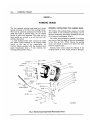
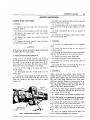
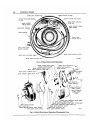
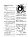
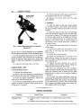
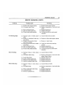
PARKING BRAKE
4-1
GftOUP 4
PARKING BHAKE
CONTENTS
Page
Data and S p e c i f i c a t i o n s . . . . . . . . . . . . . . . . . . . . . . . . . . . . . . . . . . . . . . . . . . . . .
1
External Contracting Type Parking Brake
2
................
....
Parking Brake Band Lining
3
Parking Brake Internal Expanding Type
5
Parking Brake Cable
6
Service Diagnosis
6
DATA AND SPECIFICATIONS
Type
Location . .
................
f c
......................
Internal Expanding
External Contracting
(Manual Transmission)
Propeller Shaft at Rear of Transmission
Drum Diameter
7 inches
Lining Type
Internal—Moulded Asbestos
Width
2 inches
Thickness
% inches
2
Clearance . . . \ . . . . . . . . . . . . . . . . . . . . . . . . . . . . . . . . . . . . . . . . . . . . .
.015 to .020 Inches
TIGHTENING REFERENCE
Foot-Pounds
Parking Brake Cable Bracket Clamp Bolt
20
Parking Brake Lever to Instrument Panel
20
Parking Brake Adjusting Bolt Cover Bolt
Transmission Shaft Flange Bolt Nut % . . . . . .
....................
%..............................
...........................
Inch-Pounds
130
95
6
35
50
4-2
PARKING BRAKE
GROUP 4
PARKING BRAKE
The foot operated parking brake pedal and release
handle is located to the left of the steering column.
The brake is applied by pressing down firmly on the
pedal The brake is released when the "T" shaped
handle is pulled and depressed. The pedal and release handle are serviced as a unit and need only
periodic lubrication.
A steel enclosed brake cable connects the pedal
and release handle assembly to the parking brake
located on the rear of the transmission. A l l
Chrysler Models equipped with the standard three
speed transmission have a 7 inch external contracting parking brake (Fig. 1).
EXTERNAL CONTRACTING TYPE PARKING BRAKE
The external type parking brake consists of a brake
drum bolted to the universal joint flange and an
external contracting type band, mounted at the rear
of the manual transmission (Fig. 1).
The brake lining should be replaced i f the lining
has worn so that the depth of the rivet counterbore.
is less than V32 inch. When relining the parking
brake, care should be taken not to distort the band
from its original shape.
Parking brake drums should be replaced i f the
braking surface is worn, rough, scored or damaged.
Fig. 1—External Contracting Brake (Disassembled View)
PARKING BRAKE
4-3
S E l f l C E PBOCEDUHES
PARKING BRAKE BAND LINING
(4) Drill and counterbore the end rivet holes and
rivet the ends of the lining.
a. Removal
(1) Eemove the cotter pin, pivot pin and lever
assembly (Fig. 1).
(2) Remove the adjusting nut, bolt and springs.
(3) "Remove the guide screw lock nuts, guide
screw and springs.
(4) Remove the anchor screw locking wire and
anchor screw.
(5) 'Remove the band assembly from the drum
and off of the.propeller shaft.
CAUTION
'
Take care not to lose the anchor spring as the band
is pulled off of the brake anchor.
b. Reining Broke Band (Band Removed)
If the lining is not already tailored to fit the band,
the lining must be cut to Insure tight adherence to
the band. Cut the lining % inch longer than the inside contour of the band. The rivet hole counterbores must be % of thickness of the lining.
(1) Cut off the lining- rivet heads and remove
the old lining.
(2) Thoroughly clean the inside surface of the
brake band.
(3) Place the lining within the brake band with
the ends of the lining flush with the ends of the
band (the center of the lining will have a slight
hump in i t ) .
(5) Compress the hump in the center of the lining and force the lining snugly against the brake
hand.
(6) Drill, counterbore and rivet the balance of
the lining.
(T) Chamfer the two ends of the lining to reduce
noise and- grabbing effect.
c. Installation
(1) Position the brake band over the propeller
shaft.
(2) Install the anchor spring into the recess of
the brake anchor.
(3) Holding the brake anchor spring compressed,
slide the brake band over the drum and anchor.
(4) Install the anchor screw finger tight.
(5) Install the guide bolt and locking bolts.
(6) Install the adjusting bolt, springs, and adjusting nut.
(7) Install the pivot pin through the lever assembly and spacer. Install a new cotter pin.
d. Adjustments
Before adjusting the parking brake, inspect the
vertical free play between the brake anchor bracket
and the brake anchor (Fig. 2). I f free play exceeds
.005 inch brake band distortion may occur when
brakes are applied. Excessive clearance may be reduced by compressing the anchor bracket in a vise.
(1) Place the parking brake pedal and lever assembly in the fully released position.
(2) Using a feeler gauge, adjust the anchor bolt
so that the clearance between the lining and the
drum is from .015 to .020 inch.
(3) Install locking wire through the anchor screw.
NOTE: The locking wire should not be drawn tight
as it may distort the position of the brake band.
Fig. 2—Parking Brake Adjustment
(4) Adjust the guide screw so there is a slight
drag from the bottom half of the brake band.
(5) Tighten the adjusting nut so that there is
only a slight drag from the top half of the brake
band.
(8) Apply the parking brake several times and
test for excessive dragging when released.
44
PARKING BRAKE
BRAKE ANCHOR WASHER
BRAKE SHOE ANCHOR PIN
BRAKE ANCHOR SHOE GUIDE
OUTPUT SHAFT REAR BEARING
OIL SEAI
BRAKE SHOE OPERATING
LEVER LINK
BRAKE SUPPORT
GREASE SHIELD
BRAKE SUPPORT GREASE
SHIELD SPRING
BRAKE SHOE ASSEMBLY
BRAKE SUPPORT
BRAKE SHOE
RETURN SPRING
CABLE GUIDE CLAMP
BRACKET ASSEMBLY
BRAKE SHOE ADJUSTING SCREW
BRAKE SHOE ADJUSTING SLEEVE
BRAKE SHOE ADJUSTING
NUT
53x58
fig. 3—Parking Brake Internal Expanding
BRAKE ANCHOR SHOE GUIDE
BRAKE ANCHOR WASHER
BRAKE SUPPORT GREASE SHIELD
BRAKE SHOE OPERATING LEVER LINK
BRAKE SHOE ANCHOR PIN
BRAKE SHOE ANCHOR
BRAKE SUPPORT
BRAKE SHOE & LINING ASSY
BRAKE SUPPORT
SPACER
SHAFT FLANGE & BRAKE DRUM ASSY
BRAKE ADJUSTING /
SCREW COVER /
BRAKE ADJUSTING
SCREW COVER
SCREW
SHAFT FLANGE WASHER
SHAFT FLANGE NUT
BRAKE SUPPORT GREASE SHIELD SPRING
BRAKE SHOE RETURN SPRING
BRAKE SHOE OPERATING LEVER SCREW
BRAKE SHOE OPERATING LEVER
BRAKE SHOE OPERATING LEVER SCREW LOCKWASHER
BRAKE SHOE OPERATING LEVER SCREW NUT
BRAKE SHOE ADJUSTING SCREW
BRAKE SHOE ADJUSTING NUT
BRAKE SHOE ADJUSTING SLEEVE
53x3A
Fig. 4—Parking Brake Internal Expanding (Disassembled View)
PARKING BRAKE
PARKING I R A K (Internal Expanding Type)
4-5
OPERATING*?
LEVER
^CONTROL CABLE
UIDE CLAMP
CLAMP BOLT,
NUT AND
LOCK
WASHER
(Figures 3 and 4)
All Models equipped with the automatic transmission have a 7 inch internal expanding two shoe parking brake Fig. 3).
a. Disassembly
(1) Disconnect the propeller shaft,at the transmission.
^ .
(2) Engage the holding Tool C-3281 with the
J ^ j f C O N T R O L CABLE •
companion flange, loosen and remove the companion
ty^gftMUlBfltf*^
CABLE SPRING
flange nut, lockwasher and flatwasher.
SHOE ADJUST SCREW, NUT AND SLEEVE
• BALL END 0\ CONTROL CABLE
50x137B
(3) Install'the puller Tool C-452 on the companion flange, removing flange and brake drum.
Fig. 5—Rear View of Internal Parking Brake
(4) Disengage the ball end of cable from the operating lever (Fig. 5).
stalled in the reverse position, adjustment would
(5) Separate the shoes at the bottom, allowingbe difficult.
the brake.shoe adjusting nut, screw and sleeve to
(6) Place the outer anchor guide over the anchor,
drop out, then release the shoes.
then attach the shoes with the retaining washer.
(6) Pry the brake shoe return spring up and over
(7) Turn the brake shoe adjusting nut until the
the right brake shoe pin, then work the spring out
shoes are in the fully released position, then install
of the assembly.
the brake drum.
(7) Pry out the brake shoe retaining washer and
NOTE: Be sure the brake shoes are centered on the
remove outer guide.
backing plate and are free to move.
(8) Slide each shoe out from under the guide
spring. (As the shoes are removed, the operating
(8) Adjust the brake shoes and control cable as
outlined below.
lever strut will drop out of place.)
(9) Separate the operating lever from the right
c. Adjustment
brake shoe by removing nut, lockwasher and bolt.
The brake has now been disassembled as far as
(1) Remove the adjusting screw cover plate.
necessary for replacement of worn or damaged parts.
(2) Turn the brake shoe adjusting nut, as shown
in Figure 5, to decrease shoe-to-drum clearance until
a slight drag is felt on the drum. Back off the adb. Assembly (Figure 3)
justing nut at least one full notch (using spanner
(1) Assemble the operating lever to the right
wrench Tool C-3723) or until brake drum is free.
brake shoe.
PARKING BRAKE
WASHER
(2) Slide the right and left hand brake shoes unCABLE
SEAL
der the guide spring and up on top of the inner
anchor guide.
(3) Spread the shoes and insert the operating
lever strut with the wide slot toward the operating
lever, and stamped "top" facing up.
(4) Work the shoe return spring under the grease
shield spring and secure ends in proper holes in webs
of shoes, as shown-in Figure 3.
(5) Spread the bottom of both shoes apart and install the brake shoe adjusting nut screw and sleeve.
NOTE: Install the adjusting nut> screw and sleeve
in the proper position, as shown in Figure 3. If in-
ADJUSTING
NUT
PARKING BRAKE
LEVER ASSEMBLY
62X85
Fig. 6—Parking Brake PedaL Lever and Cable Assembly
(Models SOL SC-2, SC-3)
4-6
PARKING BRAKE
(5) Pry the ball end of the cable up and out of
the operating lever slot with a screwdriver.
(6) Remove the control cable from the guide
clamp bracket.
b. Installation
(1) Slide the cable into the guide clamp bracket
at the brake support. Insert Tool C-3015 between
the spring retainer washer and the ball on the end
of cable.
(2) Hook the cable into the slot in the operating
lever, with the lever between the ball and the washer, as shown in Figure 5. The cable must be installed
so that the cable conduit is not pulled taut between
any of the fastening points. To provide free cable
operation, care must be used to prevent kinking of
the housing, also, all bends must have a radius of
6 inches or more.
Fig. ?—Parking Brake Pedal and Lever Assembly
(Models SY-1)
Be sure the two raised shoulders on the adjusting
nut are seated in the groove on the adjusting sleeve.
(3) Test the parking brake lever for travel When
properly adjusted, there should not be more than 31/4
Inches of parking brake pedal travel Never substitute a brake shoe adjustment by adjusting the
cable.
(4) Install the adjusting screw cover plate.
PARKING BRAKE CABLE
a. Removal (Figures 6 and 7)
(1) Release the parking brake.
(2) Remove the cable adjusting nut from the end
of the cable at the upper end of parking brake lever.
(3) From the engine compartment, remove the
upper end of cable from dash panel
(4) Loosen the guide clamping bolt at the brake
support, as shown in Figure 5, then remove the adjusting screw cover plate.
(3) Route cable from transmission up the front
of dash panel
(4) Install the plastic seal and washer on the
cable (Fig. 4) and insert the cable through dash
panel opening.
(5) Install the housing retainer.
(6) Insert the threaded end of the cable in the
pedal trunnion, depress the foot pedal to do so, return foot pedal to released position, and install the
cable adjusting nut.
(7) Tighten the cable adjusting nut so that the
nut is seated on the trunnion without pulling any
additional cable through the dash panel.
(8) After the adjustment has been completed,
apply and release the foot pedal several times. Then,
when fully released check to insure that the cable
adjusting nut is seated on the trunnion. Readjust
if necessary.
(9) To check for correct adjustment, apply approximately 60 pounds-foot pressure on the pad and
measure pedal travel The travel at the pad should
not be more than 3 ^ inches. With the foot pedal
fully released, the parking brake must release and
the propeller shaft revolve freely.
SERVICE DIAGNOSIS
Condition
Dragging Brake
Possible Cause
Correction
(a) Improper cable or brake adjust- (a) Adjust brake shoes and cable.
ment.
(b) Broken brake shoe return spring. (b) Replace brake shoe return spring.
PARKING BRAKE
4-7
SERVICE DIAGNOSIS—CONT'D.
Condition
Possible Cause
(c) Broken brake support spring.
(d) Oil soaked brake lining.
(e) Bent or distorted drum.
(f) Bent or broken brake shoe.
(f) Frozen brake pedal assembly.
Overheating Brake
(a) Improper cable or brake adjustment.
Broken
or misaligned brake sup(b)
port spring.
(c) Broken or disconnected brake
shoe return spring.
(d) Missing brake shoe anchor retaining washer.
(e) Bent or distorted drum.
(f) Bent or broken brake shoe.
(«r) Frozen brake pedal assembly.
Correction
(c) Eeplace brake support spring.
(d) Replace transmission oil seal and brake
shoes.
(e) Replace brake drum.
(f) Replace brake shoe.
(S) Lubricate and free up brake pedal
assembly.
(a) Adjust brake shoes and cable.
(b) Replace or align brake support spring.
(c) Replace or align brake.
(d) Install new brake shoe retaining
washer.
(e) Replace brake drum.
(f) Replace broken brake shoe.
(g) Lubricate and free up brake pedal
assembly.
Brake Grabbing
(a) Improper brake or cable adjust- (a) Adjust brake and cable.
ment.
(b) Oil soaked brake lining.
(b) Replace transmission oil seal and brake
shoes. Clean off drum.
(c) Loose brake drum.
(c) Tighten brake drum.
(d) Loose or broken anchor pin.
(d) Replace anchor pin.
(e) Warped or bent brake drum.
(e) Replace brake drum.
(f) Scored or cracked brake drum.
(f) Replace brake drum.
Brake Chattering
(a) Improper brake or cable adjust- (a) Adjust brake and cable.
ment.
(b) Oil soaked lining.
(b) Replace transmission oil seal and brake
shoes.
Replace
brake shoes.
(c) Worn or distorted brake lining.
(c)
(d) Loose anchor pin.
(d) Replace anchor pin.
(e) Replace brake drum.
(e). Scored or cracked drum.


![Cover [IP7361]_Outline](http://vs1.manualzilla.com/store/data/006290601_1-2c5dec26af4e44ba77ecb21269762c6c-150x150.png)