1
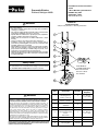
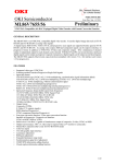
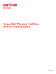
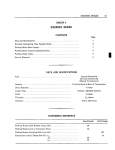
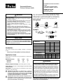
Installation & Service Instructions:
V675P
Pneumatic Division
Richland, Michigan 49083
“XM” Series Air Control Valves
1/8" Inline & Subbase, 3/2 & 4/2
ISSUED: March, 2007
Supersedes: None
DOC.# V675P, EN# 061246
! WARNING
To avoid unpredictable system behavior that can cause personal injury
and property damage:
• Disconnect electrical supply (when necessary) before installation,
servicing, or conversion.
• Disconnect air supply and depressurize all air lines connected to this
product before installation, servicing, or conversion.
• Operate within the manufacturer’s specified pressure, temperature,
and other conditions listed in these instructions.
• Medium must be moisture-free if ambient temperature is below
freezing.
• Service according to procedures listed in these instructions.
• Installation, service, and conversion of these products must be
performed by knowledgeable personnel who understand how
pneumatic products are to be applied.
• After installation, servicing, or conversion, air and electrical supplies
(when necessary) should be connected and the product tested for
proper function and leakage. If audible leakage is present, or the
product does not operate properly, do not put into use.
• Warnings and specifications on the product should not be covered by
paint, etc. If masking is not possible, contact your local representative
for replacement labels.
If this solenoid operated valve is used in a circuit with other inductive
loads, the solenoid should be electrically protected with a voltage
suppression device (e.g. transient voltage suppressor or varistor) that has
a minimum rating of 1.6 times the rated voltage of the solenoid valve and
sufficient capacity to dissipate the energy of other inductive loads.
Wiring Detail
1/2” -14 NPT
Conduit Thread
Conduit Option
Grommet Option
Symbols
2
#12
Operator
End
3/2
1 3
2 4
#14
Operator
End
4/2
1 3
2
#14
Operator
End
Safety Guide
For more complete information on recommended application
guidelines, see the Safety Guide section of Pneumatic Division
catalogs or you can download the Pneumatic Division Safety
Guide at: www.parker.com/safety
Ground
15MM 3-Pin DIN
Option
1
#12
Operator
End
4
3
#12
Operator
End
4/2
With Flow Control
3-Way Options
Port No.
1
2
3
Inlet
Cyl
Exh
3-Way, Normally Open
Exh
Cyl
Inlet
2-Way, Normally Closed
Inlet
Cyl
Plug
Introduction
2-Way, Normally Open
Plug
Cyl
Inlet
Follow these instructions when installing, operating or servicing the
product.
Selector
Inlet
Cyl
Inlet
VALVE IS NOT DESIGNED FOR FIELD SERVICE
Application Limits
These products are intended for use in general purpose compressed air
systems only.
Operating Pressure: kPa PSIG bar
Maximum Minimum 850 125 8.5
-30 -14.7 -1
Ambient Temperature Range: 0°C to 50°C (32°F to 125°F)
Voltage Range: 85-110% of rated voltage. These limits should
not be exceeded.
EXCEPTION: The 45 and 49 voltage code rated Valves may be operated
at 70-125% of the rated voltage.
!
CAUTION: An interruption of 10 milliseconds or greater to
the power supplied to the solenoid of a solenoid operated
valve may cause the valve to shift. Provision must be made
to prevent power interruption of this duration to avoid
unintended, potentially hazardous, consequences.
!
CAUTION: This valve contains solid state components that can
be damaged by transient voltage spikes, over-voltage or high
temperature. To protect against premature solenoid failure,
please read and adhere to the following:
3-Way, Normally Closed
Diverter
4-Way Options
Normal Function
Cyl
Inlet
Port No.
1
2 3
Cyl
4
Inlet CylinderExhaust Cylinder
4-Way used as 3-Way, NC
Inlet
4-Way used as 3-Way, NO
Inlet CylinderExhaust
PlugExhaust Cylinder
Plug
! WARNING
FAILURE OR IMPROPER SELECTION OR IMPROPER USE OF THE
PRODUCTS AND/OR SYSTEMS DESCRIBED HEREIN OR RELATED ITEMS
CAN CAUSE DEATH, PERSONAL INJURY AND PROPERTY DAMAGE.
This document and other information from Parker Hannifin Corporation, its
subsidiaries and authorized distributors provide product and/or system options
for further investigation by users having technical expertise. It is important
that you analyze all aspects of your application, including consequences of
any failure and review the information concerning the product or systems
in the current product catalog. Due to the variety of operating conditions
and applications for these products or systems, the user, through its own
analysis and testing, is solely responsible for making the final selection of the
products and systems and assuring that all performance, safety and warning
requirements of the application are met.
The products described herein, including without limitation, product features,
specifications, designs, availability and pricing, are subject to change by Parker
Hannifin Corporation and its subsidiaries at any time without notice.
EXTRA COPIES OF THESE INSTRUCTIONS ARE AVAILABLE FOR INCLUSION
IN EQUIPMENT / MAINTENANCE MANUALS THAT UTILIZE THESE PRODUCTS.
CONTACT YOUR LOCAL REPRESENTATIVE.
“XM” Series Air Control Valves 1/8" Inline & Subbase, 3/2 & 4/2
Inline Valve Accessories
V675P
Inline Valve on Inlet / Exhaust Manifold
Assembly
Part Number
Description
PSXM8288P
Mounting Bracket
1. Install the O-rings (Item 1) in the counterbores on top of the Manifold
(Item 2).
Electrical Connectors (9.4mm)
Indication
Voltage
Unwired
Plug
Plug with
6' Lead
None
N/A
PESC10
PESC12
LED &
Suppression
12/24VDC
PESC2020B
PESC2220B
120VAC
PESC2001F
PESC2201F
Subbase Valve and Manifold Assembly
1.Place o-ring seals (Item 2) into End Cap possessing o-ring grooves
(Item 1), and thread spacers (Item 5) into this End Cap.
2. Place the Valve on the Manifold. For 3-Way N.C. Valve operation (Item
4), line up the Solenoid end of the Valve with Port 1 on the Manifold.
For 3-Way N.O. operation (Item 5), line up the Solenoid end of the
Valve with Port 3 on the manifold. For 4-Way Valve operation (Item
6), line up the Solenoid end of the Valve with Port 1 on the Manifold.
Install the two Socket Head Cap Screws (Item 3) provided and tighten
to 6 to 10 in-lb. (.7 to 1.1 Nm) torque using a 5/64 inch hex wrench.
3. When DIN Rail Mounting Bracket is provided, install Screws through
the Manifold and secure the DIN Rail Connecting Bracket on both
ends of the Manifold.
4. Test valve for functional operation and for internal and external
leakage. If leakage is audible (most likely indicating improper
assembly) do not operate – conduct assembly again.
2.Assemble subbase (Item 3) with O-rings (Item 2) onto spacers using
subbase through-holes. Repeat for remaining manifold stations.
3
3.Place the End Cap (Item 6) without o-ring grooves on last subbase with
O-rings.
3
4.Secure entire assembly with #6-32 x.50-inch screws (Item 7) (supplied
with End Cap) and tighten with 7/64 –inch hex drive wrench (not
supplied).
6
10
4
3
5
2
4
2
10
2
4
3-Way N.C.
2
7.Test valve for functional operation and for internal and external leakage.
If leakage is audible (most likely indicating improper assembly) do not
operate – conduct assembly again.
4-Way
4-Way
3-Way N.O.
5.To assemble valves, place o-rings (Item 8) (four per subbase, supplied
with valve, Item 9)) onto the valve mounting surface on the subbase.
(Light weight grease assists in maintaining o-ring position during
assembly.)
6.Mount Valves to subbase assembly with #3-48 x 1.25 socket head
cap screws (Item 10) supplied with valve. Use 6 to 10 in-lb. (.7 to 1.1
Nm) of torque. 4-Way and 3-Way valves are mounted with Solenoids
Coils facing away from subbase delivery ports 2 and 4. For 3-Way N.O.
Functions, valves must be isolated from the other 3-Way N.C. and 4-Way
valves on the manifold. This is achieved by placing port isolator discs
(Item 4) in between the subbase of the first 3-Way N.O. Valve and the
subbase of the last 3-Way N.C. or 4-Way valve in the Subbase Manifold.
Inlet pressure is connected to Port 3 of the manifold for the 3-Way N.O.
valves. Inlet pressure is connected to the Port 1 of the manifold for the
3-Way N.C. and 4-Way valves.
6
3
1
2
1
3
Instructions for Converting NC to NO 3-Way Valves on Existing IEM Manifolds
Remove the 3-Way Valve from the Base. Replace the Valve 180° from
the original position for N.C. function. Line up the Solenoid end of the
Valve with Port 3 on the manifold. Reinstall the two Screws (Item 3)
and tighten 6 to 10 in-lb. (.7 to 1.1 Nm) torque. Turn on air pressure
and electrical power source. Test valve for proper functional operation
and for internal and external leakage.
IEM Manifold Accessories
Kit No.
4
9
2
8
9
PSXM2186P (Item 1, 3)............ Valve to IEM Mounting Kit (10 O-rings &
10 Bolts / Kit)
8
PS2190P (Not Shown)............... DIN Rail Mounting Kit, Subbase & IEM
2
4
3
2
4
1
7
6
2
3
5
4
2
3
5
2
1
Subbase Valve Accessories
Description
PSXM2194P (Not Shown).................................... IEM Blanking Plate Kit
Kit No.
Description
PSXM8100P (Item 10, 8)........................... Valve to Subbase Bolt Kit
PSXM8310P (Not Shown)...................... Subbase Blanking Plate Kit
PSXM4900P (Item 4).................................................. Isolation Plugs
PSXM31010P (Item 1, 2, 6, 7)............................ End Plate Kit (NPT)
PSXM530CP (Item 2, 3, 5).................... Manifold Subbase Kit (NPT)
Valves can be mounted in any position in most environments, in keeping
with specifications. XM valves feature a Class B insulation system and
molded coil. Valves should be mounted using the .16, (4.0mm) diameter
side mounting holes and #6 (M3.5) mounting screws. The optional
mounting bracket consists of a bracket, two #8-32 screws and two captive
lockwasher nuts. Mounting bracket adapts to any 3-Way or 4-Way valve
on either side of the valve.
Recommended Lubricant
If in-service lubricant is used, Parker F442 oil is recommended. Parker
F442 is specially formulated to promote maximum service life of air
operated equipment. Other compatible lubricants should be of straight
paraffin base mineral oil having a viscosity of 100-200 SSU @ 100°F and
an Aniline Point greater than 200°F.
!
CAUTION: Do not use synthetic, reconstituted, or oils with
alcohol content or detergent additives.
Installation & Service Instructions:
V676P
Pneumatic Division
Richland, Michigan 49083
“XM” to MicroKing Transition Kits
ISSUED: May, 2007
Supersedes: None
DOC.# V676P, EN# 070400
PSXM2190P
Transition Plate Kit
! WARNING
To avoid unpredictable system behavior that can cause personal injury
and property damage:
• Disconnect electrical supply (when necessary) before installation,
servicing, or conversion.
• Disconnect air supply and depressurize all air lines connected to this
product before installation, servicing, or conversion.
• Operate within the manufacturer’s specified pressure, temperature,
and other conditions listed in these instructions.
• Medium must be moisture-free if ambient temperature is below
freezing.
• Service according to procedures listed in these instructions.
• Installation, service, and conversion of these products must be
performed by knowledgeable personnel who understand how
pneumatic products are to be applied.
• After installation, servicing, or conversion, air and electrical supplies
(when necessary) should be connected and the product tested for
proper function and leakage. If audible leakage is present, or the
product does not operate properly, do not put into use.
• Warnings and specifications on the product should not be covered by
paint, etc. If masking is not possible, contact your local representative
for replacement labels.
Safety Guide
For more complete information on recommended application guidelines, see
the Safety Guide section of Pneumatic Division catalogs or you can download
the Pneumatic Division Safety Guide at: www.parker.com/safety
3-Way & 4-Way XM Valves to MicroKing IE Manifold
1
2
3
4
5
0.58
(15mm)
6
7
Plate MUST be
assembled with these
two holes towards
the Port 1 side of
the manifold.
3
8
! WARNING
FAILURE OR IMPROPER SELECTION OR IMPROPER USE OF THE
PRODUCTS AND/OR SYSTEMS DESCRIBED HEREIN OR RELATED ITEMS
CAN CAUSE DEATH, PERSONAL INJURY AND PROPERTY DAMAGE.
This document and other information from Parker Hannifin Corporation, its
subsidiaries and authorized distributors provide product and/or system options
for further investigation by users having technical expertise. It is important
that you analyze all aspects of your application, including consequences of
any failure and review the information concerning the product or systems
in the current product catalog. Due to the variety of operating conditions
and applications for these products or systems, the user, through its own
analysis and testing, is solely responsible for making the final selection of the
products and systems and assuring that all performance, safety and warning
requirements of the application are met.
The products described herein, including without limitation, product features,
specifications, designs, availability and pricing, are subject to change by Parker
Hannifin Corporation and its subsidiaries at any time without notice.
EXTRA COPIES OF THESE INSTRUCTIONS ARE AVAILABLE FOR INCLUSION
IN EQUIPMENT / MAINTENANCE MANUALS THAT UTILIZE THESE PRODUCTS.
CONTACT YOUR LOCAL REPRESENTATIVE.
3
1
Item
Description
Quantity
Torque
Required
1
Special Valve to Base
Mounting Screws,
#3-48 x 1-1/2 Long
2
6 to 10 In.Lb.
(.7 to 1.1 Nm)
2
XM 3/2 or 4/2 Valve
Not Included
in this Kit
3
O-rings, Transition Plate
& Manifold
4
4
Transition Plate, Top
1
5
Mounting Screws,
Bottom Transition Plate
to Base,
M3 x 12mm
2
6
O-rings, Transition Plate
2
7
Transition Plate, Bottom
1
MicroKing IEM
Not Included
in this Kit
8
6 to 10 In. Lb.
(.7 to 1.1 Nm)
“XM” to MicroKing Transition Kit
V676P
PSXM2191P
Transition Plate Kit
PSXM2192P
Transition Plate Kit
3-Way Subbase XM Valves to MicroKing 3-Way Subbase
4-Way XM Subbase Valves to MicroKing 4-Way Subbase
1
1
2
2
3
3
4
2
4
0.39
10 mm)
0.39
10 mm)
4
5
6
5
7
6
7
8
4
2
9
8
2
1
3
3
1
4
Item
Description
Quantity
Torque
Required
6 to 10 In.Lb.
(.7 to 1.1 Nm)
Item
Description
Quantity
Torque
Required
1
2
1
Standard Valve to Base
Mounting Screws,
#3-48 x 1-1/4 Long
2
6 to 10 In.Lb.
(.7 to 1.1 Nm)
Standard Valve to Base
Mounting Screws,
#3-48 x 1-1/4 Long
2
XM 4/2 Subbase Valve
Not Included
in this Kit
2
XM 3/2 Subbase Valve
Not Included
in this Kit
3
Special Male / Female
Stud
1
3
Special Male / Female
Stud
2
4
O-rings, Transition Plate
to Valve, Small
3
4
O-rings, Transition Plate
3
5
Transition Plate
1
5
O-rings, Transition Plate
to Valve, Large
1
6
Transition Plate
1
6
MicroKing Selector Plate
NC (Use if replacing NC
Valve)
1
7
1
7
MicroKing Selector Plate
NO (Use if replacing NO
Valve)
Standard Mounting
Screws,
M3 x 10mm
1
8
MicroKing 4-Way
Selector Plate
1
8
MicroKing 3-Way
Subbase
Not Included
in this Kit
9
MicroKing 3-Way
Subbase
Not Included
in this Kit
6 to 10 In. Lb.
(.7 to 1.1 Nm)
6 to 10 In. Lb.
(.7 to 1.1 Nm)
6 to 10 In. Lb.
(.7 to 1.1 Nm)