1
Page 2 of 3
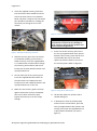
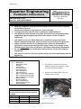
3. Insert the supplied recovery point boss
into the furthest hole towards the driver
side of the front chassis cross member.
NOTE: This boss is tapered. The narrowest
part should be inserted first, making the
narrowest part facing the rear of the
vehicle.
Figure 3: Correctly Fitted Recovery Point
WARNING
Make sure all captive nuts and any
components are free from any damage or
wear. If there is, do not fit this product and
contact Superior Engineering.
Figure 2: Fitting Of The Recovery Point Boss
4. Slide the recovery point over the chassis
crossmember (making sure the boss is
fitted correctly). Insert the supplied M14
1.5 x 130mm bolt and flat washer though
the recovery point and boss and secure
loosely with another M14 flat washer and
nylock/conelock nut.
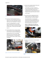
7. At the rear of the recovery point insert
the two (2) supplied 10mm thick spacers
between the recovery point and the rear
crossmember. Be sure to line these
spacers up with the holes in the rear of
the recovery point. (Refer to figure 4).
5. On the other side of the recovery point
insert the supplied M14 flat washer on
the other M14 1.5 x 130mm bolt and
loosely secure with a M14 flat washer and
nylock/conelock nut on the rear.
6. Make sure the recovery point is hard up
against the bottom of the crossmember
(This can be done with a floor jack).
Tighten the bolts up to correct torque
settings.
Figure 4: Fitting Of The 10mm Spacer
8. Lift the bash plate into position with a
suitable lifting aid.
9. In between the front of the bash plate
and the chassis crossmember, place the
two (2) supplied 20mm thick spacers and
loosely secure with the supplied M10 1.5
x 50mm dome head bolts. (As seen in
figure 5).
© Superior Engineering 499 Uhlmann Rd Burpengary QLD 4505 Australia