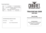
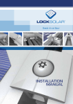
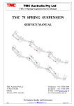
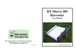
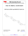
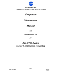
1
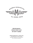
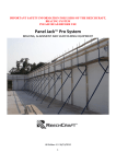
TMC Australia
u t
a Pty
Pt Ltd
td
TMC Trailer Axle Service Manual - Drum Brakes
TMC TRAILER AXLE
SERVICE MANUAL
DRUM BRAKE AXLES
TMC
8 10 15 9
TM
TM
C
T
TMC Australia Pty Ltd
78 Star Crescent
Hallam
Victoria 3803 Australia
R
T
ER
LE
LE
LE
TM
8 101 59
TM
E
IL
A
R
AX
C
IL
RA
AX
C
R
LE
I
A
TR
AX
Telephone: + 61 3 8786 3688
Facsimile: + 61 3 8786 3699
E-Mail: [email protected]
www.tmcaustralia.com.au
We Engineer Quality and Performance
2008
Page 1 of 13
TMC Australia
u t
a Pty
Pt Ltd
td
TMC Trailer Axle Service Manual - Drum Brakes
RECOMMENDED SERVICE SCHEDULE
First Service 500 km or on Delivery:
Check torque settings of all wheel nuts
- On delivery.
- After all wheel changes.
After first 5000 Km:
Check and adjust all wheel bearings.
Every 5,000 km:
Check and adjust the brakes, check brake linings for wear.
Every 25,000 km:
Lubricate slack adjusters and camshaft bushings using an EP2 type grease or equivalent.
With the axle end lifted rotate the wheels and determine if the wheel bearing’s need adjustment.
Re adjust the wheel bearings as necessary.
Every 100,000 km:
Remove the hubcaps and inspect the wheel bearings and lubricant.
Replace the lubricant if it appears badly contaminated.
Re adjust the wheel bearings and re torque the axle lock nut.
Replace the hubcaps and ensure the correct amount of lubricant is in the hub end.
Check that the hubcap gasket is not damaged. Replace as necessary.
Check the axle for brake wear, check the rest of the axle components for wear or damage.
Repair, adjust or replace as necessary.
Every 300,000 km:
Remove wash and inspect the wheel bearings, replace as necessary.
When re assembling the wheel bearings ensure they are correctly lubricated and adjusted.
See TMC Australia’s recommended wheel bearing adjustment procedures.
Note:
These are the minimum recommended service requirements, dependant on service conditions
more frequent service and maintenance schedules may be required for correct operation of the
trailer axle.
TMC
TM
810 159
81 0159
10 Stud x 285 pcd Hub
420 x 180 Brake
8 Stud x 275 pcd Hub
335 x 210 Brake
10 Stud x 335 pcd Hub
420 x 180 Brake
10 Stud x 225 pcd Hub
335 x 210 Brake
5 Spoke Spider Hub
420 x 180 Brake
TMC Australia Pty Ltd policy is one of continuous development we therefore reserve the right to change or modify the
specifications without notification.
2008
Page 2 of 13
TMC Australia
u t
a Pty
Pt Ltd
td
TMC Trailer Axle Service Manual - Drum Brakes
WHEEL BEARING ADJUSTMENT PROCEDURE
Double Axle Lock Nuts and Lock Washer – TN Wheel Bearings.
It is recommended that the wheel bearing in new axles (or whenever the wheel bearings are replaced in
service) are adjusted after the first 5000 km. The wheel bearings should then be adjusted at 100,000 km
intervals for the axle’s service life. These are the minimum recommended service requirements,
dependent on the service conditions more frequent service and maintenance schedules may be required
for correct operation of the trailer axle.
Recommended wheel bearing adjustment procedure:
1.
2.
3.
Ensure that the hub rotates freely in both directions. If any brake drag (binding) is felt temporally
back off the brake adjustment to ensure free rotation of the hub.
Rotate the hub in both directions and at the same time tighten the wheel bearing adjusting nut
until a torque setting of 150/180 Nm is reached.
Then back off the adjusting nut six (6) holes, use the axle lock washer as a guide. Refit the axle
lock washer, taking care that the wheel bearing adjustment is not disturbed. Fit the axle locknut
and tighten to a torque of 290/320 Nm.
Check the bearing end float is 0.08mm to 0.20mm. Finally check that the hub rotates freely. If it
does not rotate freely it may be necessary to redo the wheel bearing adjustment procedure. If
Necessary, now re adjust the brakes.
SPINDLE LOCK NUT
6 HO
LES
SPINDLE ADJUSTING NUT
USE THE LOCK WASHER
AS A GUIDE, SLACKEN
BACK BY 6 HOLES
LOCK WASHER
CHECK WHEEL BEARING END FLOAT IS 0.08mm TO 0.20mm.
RE ADJUST IF NECESSARY.
2008
Page 3 of 13
TMC Australia
u t
a Pty
Pt Ltd
td
TMC Trailer Axle Service Manual - Drum Brakes
WHEEL BEARING ADJUSTMENT CHECKING PROCEDURE
Double Axle Lock Nuts and Lock Washer – TN Preset Wheel Bearings.
It is recommended that the wheel bearing in new axles (or whenever the wheel bearings are replaced in
service) are checked for end float after the first 5000 km. The wheel bearings should then be re checked
for end float at 100,000 km intervals for the axle’s service life. These are the minimum recommended
service requirements, dependent on the service conditions more frequent service and maintenance
schedules may be required for correct operation of the trailer axle.
Recommended wheel bearing end float checking procedure:
1.
2.
3.
4.
Ensure that the hub rotates freely in both directions. If any brake drag (binding) is felt temporally
back off the brake adjustment to ensure free rotation of the hub.
Rotate the hub in both directions and at the same time tighten the wheel bearing adjusting nut
until a torque setting of 390/410 Nm is reached.
Fit the axle lock washer onto the axle.
Fit the axle locknut and tighten to a torque of 290/310 Nm.
Check the bearing end float is 0.08mm to 0.20mm. Finally check that the hub rotates freely. If it
does not rotate freely it may be necessary to redo the wheel bearing tightening procedure.
SPINDLE ADJUSTING NUT
SPINDLE LOCK NUT
LOCK WASHER
Note:
Preset wheel bearings are unique bearings and cannot be mixed with other bearing
types. When being serviced or replaced bearing cups and cones must be kept as
pairs or replaced as full sets. The Preset bearing cups and cones must not be mixed.
2008
Page 4 of 13
TMC Australia
u t
a Pty
Pt Ltd
td
TMC Trailer Axle Service Manual - Drum Brakes
WHEEL BEARING ADJUSTMENT PROCEDURE
Castellated Axle Nut with Split Pin – TP (Parallel) Wheel Bearings.
It is recommended that the wheel bearings in new axles (or whenever the wheel bearings are replaced in
service) are adjusted after the first 5000 km. The wheel bearings should then be adjusted at 100,000 km
intervals for the axle’s service life. These are the minimum recommended service requirements,
dependent on service conditions more frequent service and maintenance schedules may be required for
correct operation of the trailer axle.
Recommended wheel bearing adjustment procedure:
1.
Ensure that the hub rotates freely in both directions. If any brake drag (binding) is felt temporally
back off the brake adjustment to ensure free rotation of the hub.
2.
Rotate the hub in both directions and at the same time tighten the axle adjusting nut (castellated)
until a torque setting of 150/180 Nm is reached.
3.
Then back off the axle adjusting nut approximately one eighth of a turn, using the axle adjusting
nut as a guide. Refit the axle cotter (split) pin and lock in place. Take care that the wheel bearing
adjustment is not disturbed.
Check the bearing end float is 0.08mm to 0.20mm. Finally check that the hub rotates freely. If it
does not rotate freely it may be necessary to redo the wheel bearing adjustment procedure. If
Necessary, now re adjust the brakes.
BA
C
LE
HO
E
N
KO
USE THE AXLE ADJUSTING NUT AS
A GUIDE, SLACKEN BACK TO FIRST
AVAILABLE SPLIT PIN HOLE.
BEARING TAB WASHER
CHECK WHEEL BEARING END FLOAT IS 0.08mm TO 0.20mm.
RE ADJUST IF NECESSARY.
2008
Page 5 of 13
TMC Australia
u t
a Pty
Pt Ltd
td
TMC Trailer Axle Service Manual - Drum Brakes
BRAKE ADJUSTMENT – MANUAL SLACK ADJUSTERS
‘S’ Cam brakes are adjusted by the manual slack adjusters fitted to the camshafts on the axle.
1.
With the brakes released, adjust the slack adjuster until the brake linings contact the brake drum.
This is done by rotating the 19mm hexagonal nut clockwise.
2.
Adjust the 19mm hexagonal nut back one half turn or until the hub rotates freely with no brake
drag evident.
3.
Finally check that with the brakes released and applied that the angle between the brake chamber
push rod and slack adjuster is greater that 90 degrees. The angle can be adjusted by screwing the
push rod clevis backwards or forwards along the push rod thread to achieve the correct angle.
When finished always check that the push rod clevises lock nut is tightened.
Released
Applied
90
°
pl
us
19mm Hex
adjusting nut
BRAKE ADJUSTMENT - MANUAL SLACK ADJUSTER.
BRAKE ADJUSTMENT – AUTOMATIC SLACK ADJUSTERS
‘S’ cam brakes fitted with automatic slack adjusters should require no manual adjustment after the initial
installation on the axle or initial re adjustment of the brakes after brake relines. All automatic slack
adjusters have a specific set up and installation procedure as specified by the automatic slack adjuster
manufacturer. This procedure must be adhered to. If in doubt contact the manufacturer of the automatic
slack adjusters or the manufacturer’s agent for these specific procedures.
Generally, automatic slack adjusters must be re adjusted similarly to the manual slack adjusters on initial
installation or after brake relines.
Caution: Please refer to the manufacturer’s recommendations.
2008
Page 6 of 13
TMC Australia
u t
a Pty
Pt Ltd
td
TMC Trailer Axle Service Manual - Drum Brakes
AXLE HUB LUBRICATION
Grease Filled Hubs:
1.
2.
3.
The wheel bearings must be fully packed with grease, it is recommended that a wheel bearing
packer or suitable equipment is used to correctly pack the wheel bearings with grease.
Fill the hub cavity with grease as shown. The cavity is to be filled to a line running from inner
bearing cup inner diameter to outer bearing cup inner diameter.
Caution: Do not overfill the hub cavity.
After the final assembly of the hub onto the axle end, a smear of grease should be applied to the
inside of the hubcap and over the axle spindle nut/s and lock washer.
FILL THE GREASE
IN HUB CAVITY
TO THIS LINE
BEARING CUP
BEARING CUP
Oil Filled Hubs:
1.
Remove the rubber plug or screwed plug from the hubcap so that the oil can be added to the hub.
2.
Fill the hub with oil to the full level on the sight glass in the hubcap window.
3.
Allow time for the oil to flow through the wheel bearings. Top up the hub with oil to the full
mark. Caution: Do not overfill the hub.
4.
Refit the rubber plug or screwed plug back into the hubcap. Check that the plug seals.
OIL FILLER PLUG
RED RUBBER PLUG
FULL
ADD
OI
L
LE
VE
L
LE
VE
L
L
FULL
ADD
OI
OIL HUBCAP - 6 BOLT TYPE
2008
OIL FILL
LEVEL
OIL HUBCAP - SCREW IN TYPE
Page 7 of 13
TMC Australia
u t
a Pty
Pt Ltd
td
TMC Trailer Axle Service Manual - Drum Brakes
WHEEL BEARING LUBRICANTS
Grease:
Oil:
Mobil HP or an approved equivalent grease.
Mobil 85W/140 or an approved equivalent oil.
WELDING TO TMC AXLE BEAMS
Recommended welding procedures:
1.
2.
3.
4.
Before any welding is conducted on the axle tube, the axle tube must be pre heated to
100 – 1500C locally at the area to which the welding is to be done.
Caution: Do not apply excessive heat to the axle tube.
All welding is to be applied to the axle tube as near as possible to the axle’s neutral axis. Do not
weld circumferentially around the axle tube.
It is recommended that all welds are applied using small multiple fillet weld runs to achieve the
desired finished weld fillet size.
All welds must be conducted using low hydrogen rods or an approved equivalent MIG process.
TORQUE SETTINGS CHART
Wheel nuts:
M22 ISO wheel studs
¾” Unc Spider wheel studs
- 550/600 Nm.
- 200/260 Nm.
Inner Camshaft Bracket Bolts:
M10 bolt and nut
- 30/35 Nm.
Dust Cover Bolts:
M8 studs
- 20/25 Nm.
Hub Cap Bolts:
M8 studs
5/16” Unc studs
- 20/25 Nm.
- 20/25 Nm.
2008
Page 8 of 13
TMC Australia
u t
a Pty
Pt Ltd
td
TMC Trailer Axle Service Manual - Drum Brakes
38
28
37
4
34
33
23
15
3
4
40
42
1
1
2
7
5
6
6
5
9
39
25
39
24
45
24
11
11
10
44
43
26
41
36
27
16
20
31
17
32
35
21
18
22
14
19
12
29
13
30
SPARE PARTS - AXLE MODELS PFRD-225-167 and PFRD-245-167
Axles with 420mm diameter x 180mm wide brakes (16.5” x 7”).
PFRD 225
PFRD 245
PFRD 2002 167
2008
Page 9 of 13
TMC Australia
u t
a Pty
Pt Ltd
td
TMC Trailer Axle Service Manual - Drum Brakes
SPARE PARTS - AXLE MODELS PFRD-225-167 and PFRD-245-167
Axles with 420 diameter x 180 wide brakes (16.5” x 7”).
Item
1
2
3
4
5
6
7
9
10
11
12
13
14
15
16
17
18
19
20
21
22
23
24
25
26
27
28
29
30
31
32
33
34
35
36
37
38
39
40
41
2008
Model PFRD-225-167
Part Number
810146
810176
810147
9HBM08125020
9SWM08
810124
810123
810125
81HM212049
810110
810160
810158
810108
810102
810156
8106395
8103416
810094
800018
810093
800016
800002
800015
800167
810170
810171
800013
800014
810092
800003
9HBM08125025
Refer TMC
810112
810225
810144
81HM212049
81HM218210
810135
800052
800001
9HBM10150030
800005
800032
810122
800034
810117/606L
810117/606R
81HM218248
810122
810121
810113
810145
810206
810201
Model PFRD-245-167
Part Number
804345
800110
800111
800064
810153
810168
810164
810151
810166
810162
810094
800018
810093
800016
800002
800015
800167
810170
810171
800013
800014
810092
800003
9HBM08125025
Refer TMC
810112
810225
810144
800065
800065
800723
800052
800001
9HBM10150030
800005
800032
810122
800034
810117/606L
810117/606R
800064
810122
810121
810113
810145
810206
810201
Description
Hub cap – grease
Hub cap – oil
Hub cap gasket
Hub cap stud M8 x 20 long
Spring washer
Axle spindle adjusting nut
Axle spindle lock washer
Axle spindle lock nut
Outer bearing cone
Brake drum – 5 spoke spider 420x180
Brake drum – 10 stud x 285 pcd 420x180
Brake drum – 10 stud x 335 pcd 420x180
Hub assembly – 5 spoke spider
Hub assembly – 10 x 285 ISO steel
Hub assembly – 10 x 335 ISO steel
Hub assembly – 10 x 285 ISO aluminium
Hub assembly – 10 x 335 ISO aluminium
Cam roller
Cam roller retainer
Cam roller retainer – bolt on
Brake return spring
Anchor pin bush
Brake retainer spring – anchor end
Brake shoe lined – Q brake
Brake shoe lined – P brake
Brake lining set inc. rivets
Brake return spring retainer pin
Anchor pin – Q brake
Anchor pin – P brake bolt on
Dust cover
Dust cover bolt M8 x 25 long
Axle beam assembly
Wheel stud – spider hub
Wheel stud – M22 ISO x 115mm (long)
Wheel stud – M22 ISO x 100mm (short)
Outer bearing cup
Inner bearing cup
Hub seal
Slack adjuster
Inner cam support bushing
Bolt M10 x 30 long
Outer cam bushing
Camshaft seal
Camshaft washer 1 ½”
Circlip 1 ½”
Camshaft 37 spline - left hand
Camshaft 37 spline - right hand
Inner bearing cone
Camshaft washer 1 ¼”
Circlip 1 ¼”
Wheel nut – spider
Wheel nut – M22 ISO
Enclosed cam tube assembly
Enclosed cam tube support plate
Page 10 of 13
TMC Australia
u t
a Pty
Pt Ltd
td
TMC Trailer Axle Service Manual - Drum Brakes
Item
42
43
44
2008
Model PFRD-225-167
Part Number
810208
810207
810114
810169
Model PFRD-245-167
Part Number
810208
810207
810114
810169
Description
Enclosed cam tube seal – outer
Enclosed cam tube seal – inner
Hub drum bolt and conelock nut assy. ¾”UNF x 2¼”
ABS pole wheel – 100 tooth
Page 11 of 13
TMC Australia
u t
a Pty
Pt Ltd
td
TMC Trailer Axle Service Manual - Drum Brakes
38
28
37
29
4
3
4
42
1
1
2
7
5
6
6
5
9
39
25
24
11
40
10
26
43
36
27
41
15
23
20
31
34
17
32
35
21
18
22
14
19
12
30
13
SPARE PARTS - AXLE MODELS PFRD-225-138 and PFRD-245-138
Axles with 335 diameter x 210 wide brakes (13.18” x 8.25”).
PFRD 225
PFRD 245
PFRD 2002 138
2008
Page 12 of 13
TMC Australia Pty Ltd
TMC Trailer Axle Service Manual - Drum Brakes
SPARE PARTS - AXLE MODELS PFRD-225-138 and PFRD-245-138
Axles with 335 diameter x 210 wide brakes (13.18” x 8.25”).
Item
1
2
3
4
5
6
7
9
10
11
12
13
14
15
17
18
19
20
21
22
23
24
25
26
27
28
29
30
31
32
33
35
36
37
38
39
40
41
42
43
2008
Model PFRD-225-138
Part Number
810146
810176
810147
9HBM08125020
9SWM08
810124
810123
810125
81HM212049
810103
810185
810177
810188
8106434
810094
800018
810093
810101
800002
810095
810096/810097
800013
810092
810084
9HBM08125025
Refer TMC
810225
810144
81HM212011
81HM218212
810135
810120
800001
9HBM10150030
800005
800032
810122
810105/616L
810105/616R
81HM218248
810122
810121
810145
810091
810087
810081
810082
810169
Model PFRD-245-138 Description
Part Number
804345
Hub cap – grease
Hub cap – oil
Hub cap gasket
Hub cap stud M8 x 20 long
Spring washer
800110
Axle spindle adjusting nut
800111
Axle spindle lock washer
Axle spindle lock nut
800064
Outer bearing cone
810103
Brake drum – 8 stud x 275 pcd 335x210
Brake drum – 10 stud x 225 pcd 335x210
810179
Hub assembly – 8 x 275 ISO steel
Hub assembly – 10 x 225 ISO steel
Hub assembly – 8 x 275 ISO aluminium
810094
Cam roller
800018
Cam roller retainer
810093
Cam roller retainer – bolt on
810101
Brake return spring
800002
Anchor pin bush
810095
Brake shoe lined – P brake
810096/810097
Brake lining set inc. rivets
800013
Brake return spring retainer pin
810092
Anchor pin – P brake bolt on
810084
Dust cover
9HBM08125025
Dust cover bolt M8 x 25 long
Refer TMC
Axle beam assembly
810225
Wheel stud – M22 ISO x 115mm (long)
810144
Wheel stud – M22 ISO x 100mm (short)
800065
Outer bearing cup
800065
Inner bearing cup
800723
Hub seal
810120
Slack adjuster
800001
Inner cam support bushing
9HBM10150030
Bolt M10 x 30 long
800005
Outer cam bushing
800032
Camshaft seal
810122
Camshaft washer
810105/616L
Camshaft 10 spline - left hand
810105/616R
Camshaft 10 spline - right hand
800064
Inner bearing cone
810122
Camshaft washer
810121
Camshaft circlip
810145
Wheel nut – M22 ISO
810091
Enclosed cam tube assembly
810087
Enclosed cam tube support plate
810081
Enclosed cam tube seal – outer
810082
Enclosed cam tube seal – inner
810169
ABS pole wheel – 100 tooth
Page 13 of 13