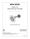
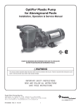
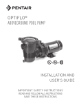
1
OptiFlo® Plastic Pump for Aboveground Pools Installation, Operation & Service Manual Listed Listed PUMP IS DESIGNED AND INTENDED FOR USE TO CIRCULATE WATER IN ABOVEGROUND SWIMMING POOLS. WARNING This manual contains important safety instructions which must be furnished to the end user. Failure to read and follow instructions could result in serious personal injury and/or major property damage. IMPORTANT SAFETY INSTRUCTIONS READ AND FOLLOW ALL INSTRUCTIONS SAVE THESE INSTRUCTIONS Pentair Water Pool and Spa, Inc. 1620 Hawkins Ave., Sanford, NC 27330 • 800-831-7133 or (919) 566-8000 10951 West Los Angeles Ave., Moorpark, CA 93021 • 800-831-7133 or (805) 553-5000 www.pentairpool.com - www.staritepool.com P/N 152012 Rev. A 11-15-10 1 OptiFlo® Engineered Plastic Pump Installation, Operation & Service Manual Table of Contents SECTION I. HOW YOUR PUMP WORKS ................................................................................................ 3 SECTION II. INSTALLATION ................................................................................................................. 3-6 SECTION III. PUMP OPERATION AND MAINTENANCE ....................................................................... 6 SECTION IV. SEAL REPLACEMENT PROCEDURE ............................................................................ 6-7 SECTION V. WINTERIZING PROCEDURE .............................................................................................. 7 SECTION VI. TROUBLESHOOTING GUIDE ............................................................................................. 8 SECTION VII. TECHNICAL DATA ........................................................................................................ 9-12 WARNING To reduce the risk of injury, do not permit children to use this product unless they are closely supervised at all times. WARNING Before installing this product, read and follow all warning notices and instructions accompanying this pump. Failure to follow safety warnings and instructions can result in severe injury, death, or property damage. Call (800) 831-7133 for additional free copies of these instructions. Important Notice Attention Installer. This manual contains important information about the installation, operation and safe use of this product. This information should be given to the owner/operator of this equipment. PUMP SAFETY INSTRUCTIONS When installing and using this electrical equipment, basic safety precautions should always be followed, including the following: WARNING RISK OF ELECTRICAL SHOCK OR ELECTROCUTION This pool pump must be installed by a licensed or certified electrician or a qualified pool serviceman in accordance with the National Electrical Code and all applicable local codes and ordinances. Improper installation will create an electrical hazard which could result in death or serious injury to pool users, installers, or others due to electrical shock, and may also cause damage to property. Always disconnect power to the pool pump at the circuit breaker before servicing the pump. Failure to do so could result in death or serious injury to serviceman, pool users or others due to electric shock. WARNING Risk of Electrical Shock. Connect only to a grounding type receptacle protected by a ground-fault circuit-interrupter (GFCI). Contact a qualified electrician if you cannot verify that the receptacle is protected by a GFCI. WARNING Do not bury the electrical cord. Locate the cord to minimize the abuse from lawn mowers, hedge trimmers, and other equipment. WARNING To reduce the risk of electrical shock, replace damaged cord immediately. P/N 152012 Rev. A 11-15-10 2 WARNING To reduce the risk of electrical shock, do not use an extension cord to connect unit to electric supply; provide a properly located outlet. WARNING For continued protection against possible electrical shock, this unit is to be mounted to the base in accordance with the installation instructions. Important Notice This pump operates with electrical voltage, and can generate both vacuum and pressure in the water system. When properly wired and plumbed, this pump will operate in a safe manner. CAUTION This pump is for use with permanently installed pools and may also be used with hot tubs and spas. Do not use with storable pools unless pump is protected by factory installed double insulated enclosure. A permanently installed pool is constructed in or on the ground or in a building such that it cannot be readily disassembled for storage. A storable pool is constructed so that it may be readily disassembled for storage and reassembled to its original integrity and has a maximum dimension of 18 feet and a maximum wall height of 42 inches. READ AND FOLLOW ALL SAFETY INSTRUCTIONS SECTION I. HOW YOUR PUMP WORKS Your centrifugal pump is designed to operate for years with proper maintenance. The pump housing, seal plate, hair and lint pot and impeller are made from high quality thermoplastic materials. These materials have been selected for their corrosion resistance nature. When installed, operated and maintained in accordance with these instructions, your pump will provide years of service. Your centrifugal pump is driven by an electric motor. The motor is directly attached to the pump impeller. As the electric motor turns it causes the impeller to turn and this causes the water to flow. The water flows into the hair and lint pot inlet and through the basket assembly to pre-strain large particles. The flow then enters the center of the pump housing. If the pump does not contain the hair and lint pot assembly, the flow simply enters the center of the pump housing. The flow goes through the impeller and out the pump discharge port. 2-Speed Pump Models: The performance of this pump will be the same at high speed as the same model single speed pump, hydraulically. At low speed the pump will produce one half the flow and 1/4 the pressure of high speed. However, the pressure required by the filter and pool plumbing at half flow will also be greatly reduced due to much lower system friction. These lower friction losses result in good energy savings. At one half flow (low speed) the electrical energy savings are 60% for equal amounts of circulated water. Turn the motor to low speed for quiet operation and electrical cost savings. Since the pump should be operated mostly at low speed for cost savings, minor adjustments may be required in the automatic chlorine dispenser, the skimmers and the heater due to the lower flow. (See the equipment manufacturer’s operation manuals.) Pool owners should use high speed for vacuuming the pool, quick filtering action, priming the system, and to keep up with heavy bathing loads. SECTION II. INSTALLATION 1. Check carton for any evidence of damage due to rough handling in shipment. If carton or any pump components are damaged, notify freight carrier immediately. 2. After inspection, carefully remove pump from carton. 3. The pump should be secured to a flat solid foundation, high enough to prevent flooding of the motor. A sheltered location is best, being sure to allow for adequate ventilation. P/N 152012 Rev. A 11-15-10 3 4. Provide space and lighting for routine maintenance access. Do not mount electrical controls directly over pump. 5. The pump should be installed as near to the pool or spa as practical. Avoid installing the pump above the water level. Suction lifts of more than 1/2 foot will cause very long priming times, and potentially damage the pump. 6. The location should provide for adequate floor drainage to prevent flooding. 7. When installing your pump, remember to provide valves or other means to disconnect the pump suction and discharge for servicing. 8. Never store pool chemicals within 10 ft. of your pool filter and pump. Pool chemicals are corrosive and should always be stored in a cool, dry, well ventilated area. WARNING Chemical fumes and/or spills can cause severe corrosive attack to the filter and pump structural components. Structurally weakened filter or pump components can cause filter, pump or valve attachments to separate and could cause severe bodily injury or property damage. 9. Assemble piping and pipe fittings to pump and valve. All piping must conform to local and state plumbing and sanitary codes. 10. Use Teflon® tape or pipe sealants on all male connections of pipe and fittings. Use only pipe sealant compounds suited for plastic pipe. Support pipe to prevent strains on filter, pump or valve. DO NOT USE PETROLEUM BASED PRODUCTS. 11. Avoid over tightening the pipe threads when connecting fittings to the pump. Proper procedure is to apply a pipe sealant to the thread and then install hand tight plus 1 1/2 turns. DO NOT OVER TIGHTEN. 12. Long piping runs and elbows restrict flow. For best efficiency use the fewest possible fittings, large diameter pipe (at least 1 1/2”) & locate equipment as close to the pool as possible. The pump suction line should not be smaller than the pipe size on the inlet of the pump. 13. It is essential that the suction line be free of air leaks and air traps. WARNING Blockage of suction fittings can cause severe or fatal injury due to drowning. Small children using pool/spa equipment must always have close adult supervision. 14. Suction fittings must conform to ASME/ANSI A 112.19.8 M Standards. Use double suction fittings. 15. The maximum operating pressure of this unit is 25 pounds per square inch. Never operate this pump above this pressure. This pump is not intended to be operated in series with other pumps. WARNING To reduce the risk of injury, do not permit children to use this product unless they are closely supervised at all times. 16. Wiring of this pump should be performed by a licensed electrician in accordance with the National Electrical Code or your local electrical code. WARNING Never work on pump while it is running or power is still connected; hazardous voltage can cause severe or fatal injury. A suitable ground fault interrupter should always be installed at the power supply source of this unit. P/N 152012 Rev. A 11-15-10 4 17. The pump motor must be wired for the proper voltage in accordance with the wiring diagram supplied with the motor. Wiring the motor with the incorrect supply voltage will cause damage to the motor and void the warranty. 18. The wiring to the motor should be kept as short as possible and large enough NOT to cause an excessive voltage drop. Use the wire size table as a guide in selecting minimum conductor size. RECOMMENDED CIRCUIT BREAKER AND WIRING DATA MOTOR HP BRANCH CIRCUIT VOLTS Hz/PHASE 3/4 15 A 1 DIST. IN FT. OF BRANCH CIRCUIT 0-50 FT. 50-100 FT. 115/60/1 #14 #14 MIN. SERVICE 15 A 115/60/1 #12 #12 WIRE 1-1/2 20 A 115/60/1 #12 #10 SIZE 1-1/2 15 A 230/60/1 #14 #14 TO MOTOR 19. Install, ground and bond wire according to local or National Electrical Code requirements. GROUNDING 20. Permanently ground motor. Use green terminal provided under motor canopy or access plate; use size and type wire required by code. Connect motor ground terminal to electrical service ground. On cord connected circuits, check for proper grounding. BONDING - (for permanently wired pumps) 21. The National Electrical Code Article 680-22 requires that the motor be electrically bonded to appropriate permanently installed pool or spa/hot tub structure by a solid copper conductor no smaller than No. 8 AWG. Bonding wire should be connected from the accessible wire connector on the motor shell to all metal parts of the swimming pool, spa or hot tub structure and to all electrical equipment, metal conduit and metal piping within 5 feet of the inside walls of a swimming pool, spa or hot tub. A grounding lug is provided on the exterior of the motor shell for this purpose. WARNING (For cord and plug-connected units) Do not bury cord. Locate cord to minimize abuse from lawn mowers, hedge trimmers and other equipment. WARNING (For cord and plug-connected units) To reduce the risk of electric shock, replaced damaged cord immediately. WARNING (For cord and plug-connected units) To reduce the risk of electric shock, do not use extension cord to connect unit to electric supply; provide a properly located outlet. CAUTION Do not install within an outer enclosure or beneath the skirt of a hot tub or spa unless so marked. P/N 152012 Rev. A 11-15-10 5 INITIAL START-UP: 1. Relieve all system pressure and open all air bleeders on total hydraulic system prior to starting the pump. See filter owner's manual. 2. Ensure that all fittings, clamps, closures and couplings are tight and in accordance with equipment manufacturer's recommendations. 3. Open suction and discharge valving to allow free flow of water. On flooded suction pumps with strainer pot the water source is higher than the pump. The water will flow into the pump strainer pot and the pot will fill with water. On pumps without strainer pot the water will fill the pump housing. 4. On non-flooded suction systems the pot lid clamp will have to be removed by rotating the lid counter-clockwise to a stop and lifting the clamp. 5. The pump strainer pot should be filled with water up to suction opening on the pump. 6. It is good practice to lubricate the lid o-ring with silicone lubricant each time the lid is removed. The o-ring should be cleaned and inspected every time the strainer pot is opened. 7. The lid should be replaced on the pot by aligning the clamp ears with the slots on the strainer pot. Press the lid and clamp down and twist the clamp clockwise to engage. 8. The pump is now ready to prime. Turn the motor on and the pump will prime. The time to prime will depend on the suction lift and the distance and size of suction piping. Turn off power if the pump does not prime within five minutes and refer to the Troubleshooting Guide section of this manual. NOTICE Never run the pump dry. Running the pump dry may damage the seals and pump housing. This could allow water leakage and flooding. SECTION III. PUMP OPERATION AND MAINTENANCE WARNING DO NOT open the strainer pot if pump fails to prime or if pump has been operating without water in the strainer pot. Pumps operated in these circumstances may experience a build up of vapor pressure and may contain scalding hot water. Opening the pump may cause serious personal injury. In order to avoid the possibility of personal injury, make sure the suction and discharge valves are open and strainer pot temperature is cool to touch, then open with extreme caution. The strainer basket in the pump should be inspected and cleaned twice each week. Remove the clear lid and the basket, and clean debris from basket. Inspect the lid o-ring; if damaged, replace. The pump seal requires no lubrication. Refer to motor service centers for motor servicing. SECTION IV. DISASSEMBLY/ASSEMBLY PROCEDURE FOR SEAL REPLACEMENT WARNING Never work on pump while it is running or power is still connected. Hazardous voltage can cause severe or fatal injury. 1. Stop pump and relieve system pressure. 2. Disconnect motor power at Circuit Breaker. P/N 152012 Rev. A 11-15-10 6 3. Close suction and discharge valves. 4. Use extreme care when handling the mechanical seal. The mating seal surfaces are polished and are easily damaged. 5. The mechanical seal can be changed without disconnecting piping by removing 4 bolts (see item 14 on page 9) and pulling the motor with pump seal plate and impeller assembly away from front pump housing body. 6. Remove impeller and rotating portion of seal by holding motor shaft and rotating the impeller counter-clockwise when facing the shaft extension on the motor. 7. The rotating portion of the seal can now be removed from the impeller. Clean the impeller hub and lubricate with soapy water. Wipe off shining carbon sealing surface of new mechanical seal with a clean tissue to remove oily fingerprints or other foreign materials. The new rotating seal can be pressed back onto the impeller. 8. To remove the stationary ceramic seal seat, first loosen the four motor bolts which run through the entire length of the motor into the seal plate. Remove the seal plate from the motor. Press the ceramic seat and rubber gasket out of the seal plate. 9. Clean the seal plate seal area and lubricate with soapy water. Press the new ceramic seal and gasket into the seal plate, being sure it is fully seated. Wipe off the ceramic sealing surface with a clean tissue to remove oily fingerprints or foreign substances. 10. Place the seal plate on the motor and carefully align the four motor through bolts. Secure the seal plate onto the motor being careful not to overtighten the bolts. Gradually bring bolts up to final tightness by moving across in a crisscross pattern. 11. Check the position of the mechanical seal set in the seal plate and ensure the motor shaft is in the center of the seal set. 12. Screw the impeller with new rotating seal onto the motor shaft. Rotate the motor shaft to make sure the impeller is not touching the seal plate. 13. Clean the seal plate “O” Ring and check to make sure it is in position. Replace the motor and seal plate on the front pump housing body and bolt into position with 4 bolts. Gradually bring bolts up to final tightness by moving across in a criss-cross pattern. 14. Refer to initial start-up procedures to restart the pump. SECTION V. WINTERIZING PROCEDURE NOTICE Allowing the water to freeze in pump will damage the pump and cause potential water damage/flooding and potential property damage. 1. Drain all water from pump housing and piping when freezing temperatures are expected. A drain plug is provided to drain the pump. If the pump has a strainer pot both the strainer drain plug and the housing drain plug should be removed. If pump has no strainer pot then only remove the housing plug. 2. If the pump can be removed and placed in an inside dry location this should be done. 3. For an outdoor unprotected location it is best to protect the equipment in a weatherproof enclosure. 4. Do not wrap the motor with plastic because condensation could form inside the motor. 5. In installations where the pump cannot be drained a 40% propylene glycol 60% water solution will protect to -50° F. NOTICE Do not use anti-freeze solutions except propylene glycol, as other anti-freeze is highly toxic and will damage the pump. P/N 152012 Rev. A 11-15-10 7 SECTION VI. TROUBLESHOOTING GUIDE The following are some common causes of problems that may arise. PROBLEM CAUSE REMEDY Pump will not prime. No water in strainer pot. Add water to pot. Strainer pot lid is not tight. Tighten lid. Damaged lid o-ring. Replace o-ring. Water level is below skimmer. Adjust pool water level. Strainer basket or skimmer basket is clogged. Clear basket. Closed valve in piping system. necessary valves. Check all valves and open all Pump is on low speed (two-speed units only). Adjust to high speed. Air leak in suction line. Find and fix leak. Water level is too low and the pump cannot lift. Adjust pump level and insure it is below water level. Filter is dirty. Clean filter. Restriction in return line. Open return line restriction. Strainer basket or skimmer basket clogged. Clean basket. Clogged impeller. Clean obstruction. Air leak in suction line. Find and fix leak. Restriction in suction line. Find and open restriction. Power switch is off. Check power switch and reset. Circuit breaker has tripped. Check circuit breaker and reset; if retrips contact electrician. Pump is in off-mode of a timer controlled circuit. Check timer mode. Low flow — high filter pressure. Low flow — low filter pressure. Motor does not turn. Motor terminal connections are incorrect.Have terminal connections checked by electrician. Motor over-heating. Motor shaft is locked by bad bearing. Have motor bearings replaced or replace pump. Electrical supply connections are incorrect. Have terminal connections checked by electrician. Wiring to pump is undersized. Consult electrician to rewire pump. Power Company supply voltage is low. Notify Power Company. Ventilation is inadequate for motor. P/N 152012 Rev. A 11-15-10 8 Remove any restrictions to air flow. SECTION VII. TECHNICAL DATA REPLACEMENT PARTS 9 15 7 6 2 3 11 13 10 12 5 8 1 14 4 Item No.Part No. 1 2 3 3 3 4 5 6 7 8 9 10 11 12 13 14 357161 354545 354552 350017 350018 192115 357213 357255 357227 357228 357239 357254 355667 357215 350103 98209000 Description Drain Plug, 3 req. Mechanical Seal Impeller – 3/4 hp, 1 hp SPL Impeller – 1 hp, 1.5 hp SPL Impeller – 1.5 hp O-ring, 3 req. Volute Assembly O-ring 2-357, 2 req. Lid Pot Assembly Clamp Ram & Cam 1/4-20 Square Nut, 4 req. Basket Seal Plate O-ring 1/4-20 x 1.5 Machine Screw, 4 req. FOR MOTOR REPLACEMENT CONSULT FACTORY CUSTOMER SERVICE (800) 831-7133 NOT SHOWN 79137800 Cord – 3 Ft. long, Standard 15 Amp Plug 155234 Cord – 3 Ft. long, Twist Lock 15 Amp Plug P/N 152012 Rev. A 11-15-10 9 REPLACEMENT PARTS (BASE MOUNTED UNITS) For cord and plug connected units, the base should be mounted as shown. 4 3 5 2 6 1 7 8 Item No. Part No. 1 2 10 3 4 5 6 7 8 9 10 9 Description 354621 Enclosure Housing FOR MOTOR REPLACEMENT CONSULT FACTORY CUSTOMER SERVICE (800) 831-7133 354881 Cap, CSA Mtr. Enclsr. w/3 Screws 154716 Screw - Self Tapping HH #10, 3 req. 155371 Cord - 25 ft. 16 Ga. Power Supply 155187 Switch Toggle Double Insulated 155193 Conn. #16 Switch 354658 Insulated Foam w/Adhsve. Back 155109 Nut - T4 Prong 153263 Base CSA 4 in. High DIMENSIONAL DATA Suction 9.33" Vertical Discharge 10.00" 7.26" 7.75" 3.50" 4.09" P/N 152012 Rev. A 11-15-10 10 PUMP CURVES Pentair Pool Products® OptiFlo® Series 50 Hz Pump Curves 35 10 30 6 4 Total Dynamic Head in Ft. of Water METERS OF WATER 8 25 1. 20 5 1 15 3/ 4 10 HP HP HP 2 5 0 0 0 10 20 30 40 50 60 70 80 Flow Rate in US GPM 0 5 10 15 CUBIC METERS PER HOUR Pentair Pool Products® OptiFlo® Series 60 Hz Pump Curves 60 50 10 5 Total Dynamic Head in Ft. of Water METERS OF WATER 15 40 30 20 1.5 HP 1.0 HP 3/4 HP 10 0 0 0 0 P/N 152012 Rev. A 11-15-10 10 20 30 5 40 50 60 Flow Rate in U.S GPM 10 CUBIC METERS PER HOUR 11 70 15 80 90 20 100 © 2010 Pentair Water Pool and Spa, Inc. All rights reserved. 1620 Hawkins Ave., Sanford, NC 27330 • (919) 566-8000 10951 West Los Angeles Ave., Moorpark, CA 93021 • (800) 553-5000 OptiFlo® and Pentair Water Pool and Spa® are registered trademarks of Pentair Water Pool and Spa, Inc. Teflon® is a registered trademark of E.I. Du Pont De Nemours and Company Corporation. Unless noted, names and brands of others that may be used in this document are not used to indicate an affiliation or endorsement between the proprietors of these names and brands and Pentair Water Pool and Spa, Inc. Those names and brands may be the trademarks or registered trademarks of those parties or others. Protected by U.S. Patents Pending and all corresponding foreign counterparts. P/N 152012 Rev. A 11-15-10 12