1
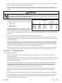
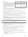
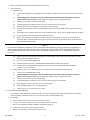
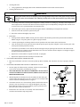
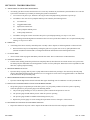
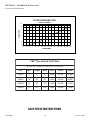
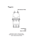
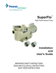
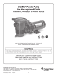
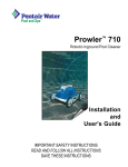
FNS® Plus Vertical Grid D.E. Filter Owner's Manual
IMPORTANT SAFETY INSTRUCTIONS
READ AND FOLLOW ALL INSTRUCTIONS
SAVE THESE INSTRUCTIONS
Table of Contents
SECTION I.
FILTER INSTALLATION. .......................................................................................... 1
SECTION II.
FILTER OPERATION. ................................................................................................ 2
SECTION III. TROUBLE SHOOTING. ............................................................................................. 8
SECTION IV. TECHNICAL DATA. ............................................................................................. 9-10
WARNING
Before installing this product, read and follow all warning notices and instructions accompanying this filter. Failure to follow
safety warnings and instructions can result in severe injury, death, or property damage. Call (800) 831-7133 for additional free
copies of these instructions.
Important Notice
Attention Installer.
This manual contains important information about the installation, operation and safe use of this product.
This information should be given to the owner/operator of this equipment.
SECTION I.
A.
FILTER INSTALLATION
GENERAL INFORMATION.
1.
The filter should be mounted on a level concrete slab. Position
the filter so that instructions, warnings and the pressure gauge
are visible to the operator. It also should be positioned so that
the piping connections, control valve and drain port are
convenient and accessible for servicing and winterizing.
2.
Install electrical controls (e.g., on/off switches, timers, control
systems, etc.) at least five (5) feet from the filter. This will
allow you enough room to stand clear of the filter during
system start up.
3.
Allow sufficient clearance around the filter to permit visual
verification that the clamp is properly installed around the tank
flanges, see Figure 1.
a.
Figure 1.
Tap the clamp with a mallet or similar tool to ensure uniform
loading during clamp tightening.
Pentair Water Pool and Spa, Inc.
1620 Hawkins Ave., Sanford, NC 27330 • (800) 831-7133 • (919) 566-8000
10951 West Los Angeles Ave., Moorpark, CA 93021 • (800) 831-7133 • (805) 553-5000
Visit us on the Internet at: www.pentairpool.com or www.staritepool.com
Rev. H 4-2-08
1
P/N 190033
4.
Allow sufficient space above the filter to remove the filter lid for cleaning and servicing. This distance will vary with the model of
filter you are using. See Table 1 for the required vertical clearance.
5.
Position the filter to safely direct water drainage. Rotate the High Flow™ manual air relief valve to safely direct purged air or
water. Water discharged from an improperly positioned filter or valve can create an electrical hazard as well as damage
property.
WARNING
Risk of electrical shock or electrocution. Position the filter and High Flow™ manual air relief valve to safely direct water drainage
and purged air or water. Water discharged from an improperly positioned filter or valve can create an electrical hazard that can
cause severe personal injury as well as damage property.
6.
Your filter requires one of the following Pentair Water Pool
and Spa® accessories which must be purchased separately.
a.
b.
c.
Push-Pull valve
Multiport valve
Bulkhead union set
Table 1.
Model
FNSP 24
FNSP 36
FNSP 48
FNSP 60
P/N
180006
180007
180008
180009
Vertical
Clearance Req. NSF
Size
24
36
48
60
sq.
sq.
sq.
sq.
ft.
ft.
ft.
ft.
48 in.
62 in.
74 in.
86 in.
no
yes
yes
yes
7.
Make all plumbing connections in accordance with local
plumbing and building codes. Filter plumbing connections
are provided with an O-ring seal. To avoid damage to the
O-rings, use only a silicone base lubricant on the O-rings. Do not use pipe joint compound, glue or solvent on the bulkhead
connections.
8.
Remove the plug from the top of the filter lid and install the pressure gauge before use.
9.
The maximum working pressure of this filter is 50 psi. Never subject this filter to pressure in excess of this amount - even when
conducting hydrostatic pressure tests. Pressures above 50 psi can cause the lid to be blown off, which can result in severe injury,
death or property damage.
When performing hydrostatic pressure tests or when testing for external leaks of the completed filtration and plumbing
system, ensure that the maximum pressure that the filtration system will be subjected to DOES NOT EXCEED THE
MAXIMUM WORKING PRESSURE OF ANY OF THE COMPONENTS CONTAINED WITHIN THE SYSTEM. In most
cases, the maximum working pressure will be stated on each component of the system.
If doubt exists as to the pressure to which the system will be subjected, install an ASME approved automatic Pressure Relief
or Pressure Regulator in the circulation system for the lowest working pressure of any of the components in the system.
SECTION II.
FILTER OPERATION
A. GENERAL INFORMATION.
1.
This filter operates under pressure. When clamped properly and operated without air in the water system, this filter will
operate in a safe manner.
2.
The maximum working pressure of this filter is 50 psi. Never subject this filter to pressure in excess of this amount - even when
conducting hydrostatic pressure tests. Pressures above 50 psi can cause the lid to be blown off, which can result in severe
injury, death or property damage.
When performing hydrostatic pressure tests or when testing for external leaks of the completed filtration and plumbing
system, ensure that the Maximum Pressure that the filtration system will be subjected to DOES NOT EXCEED THE
MAXIMUM WORKING PRESSURE OF ANY OF THE COMPONENTS CONTAINED WITHIN THE SYSTEM. In most
cases, the maximum working pressure will be stated on each component of the system.
If doubt exists as to the pressure to which the system will be subjected, install an ASME approved automatic Pressure
Relief or Pressure Regulator in the circulation system for the lowest working pressure of any of the components in the
system.
3.
The pressure gauge is the primary indicator of how the filter is operating. Maintain your pressure gauge in good working order.
4.
Never operate filter in excess of three (3) minutes without use of diatomaceous earth. Diatomaceous earth is the substance
that filters the water, the filter cloth merely supports the diatomaceous earth. Operating without diatomaceous earth will
damage filter elements and shorten filtering cycles.
P/N 190033
2
Rev. H 4-2-08
WARNING
THIS FILTER OPERATES UNDER HIGH PRESSURE. WHEN ANY PART OF THE CIRCULATING SYSTEM, e.g.,
CLAMP, PUMP, FILTER, VALVE(S), ETC. IS SERVICED, AIR CAN ENTER THE SYSTEM AND BECOME
PRESSURIZED. PRESSURIZED AIR CAN CAUSE THE LID TO BE BLOWN OFF WHICH CAN RESULT IN
SEVERE INJURY, DEATH, OR PROPERTY DAMAGE. TO AVOID THIS POTENTIAL HAZARD, FOLLOW THESE
INSTRUCTIONS.
1.
BEFORE REPOSITIONING VALVE(S) AND BEFORE BEGINNING THE ASSEMBLY, DISASSEMBLY, OR
ADJUSTMENT OF THE CLAMP OR ANY OTHER SERVICE OF THE CIRCULATING SYSTEM: (A) TURN THE
PUMP OFF AND SHUT OFF ANY AUTOMATIC CONTROLS TO ENSURE THE SYSTEM IS NOT
INADVERTENTLY STARTED DURING THE SERVICING; (B) OPEN HIGH FLOW™ MANUAL AIR RELIEF
VALVE; (C) WAIT UNTIL ALL PRESSURE IS RELIEVED.
2.
WHENEVER INSTALLING THE FILTER CLAMP FOLLOW THE FILTER CLAMP INSTALLATION
INSTRUCTIONS EXACTLY.
3.
ONCE SERVICE ON THE CIRCULATING SYSTEM IS COMPLETE FOLLOW SYSTEM RESTART
INSTRUCTIONS EXACTLY.
4.
MAINTAIN CIRCULATION SYSTEM PROPERLY. REPLACE WORN OR DAMAGED PARTS IMMEDIATELY,
e.g., clamp, pressure gauge, valve(s), O-rings, etc.
5.
BE SURE THAT THE FILTER IS PROPERLY MOUNTED AND POSITIONED ACCORDING TO
INSTRUCTIONS PROVIDED.
B. CLAMP INSTALLATION INSTRUCTIONS.
These instructions MUST BE FOLLOWED EXACTLY to prevent the lid from blowing off during system restart or later
operation.
1.
Perform the following steps before working on any part of the circulating system, e.g., clamp, pump, filter, valve(s), etc.
a.
Turn the pump off and shut off any automatic controls to ensure that the system is not inadvertently started during
servicing.
b.
Open the High Flow™ manual air relief valve until it snaps into the full open position (this only requires a quarter turn
counter clockwise).
c.
Wait until all pressure is relieved. Never attempt to assemble, disassemble or adjust the filter clamp while there is
any pressure in the filter.
2.
Be certain the O-ring is in position in the lower tank half. Press the filter lid over the lower tank half sandwiching the O-ring
in between.
3.
Holding the ends of the filter clamp apart, position the center segment of the filter clamp over both upper and lower tank
flanges. Bring the ends of the filter clamp together, while inserting the T-Bolt into the trunnion; see Figure 2.
4.
Using Figure 2 as a guide - place washer (large I.D.) and the tension-indicating spring on the barrel nut. Place the second
washer (small I.D.) on the T-Bolt. Hand-tighten nut. Recheck filter
clamp for proper seating on tank flanges.
5.
Begin to tighten nut using a 7/8 in. wrench. Then tap around the
outside of the filter clamp with a mallet (or similar tool) to ensure
uniform loading and proper seating of the clamp. Continue tapping
and tightening until the spring coils touch each other. Do not
tighten beyond this point.
6.
Follow the instructions in Section C, SYSTEM RESTART
INSTRUCTIONS, which follows.
7.
The spring coils should be checked at least once per month to
ensure that they continue to touch each other, indicating that the
clamp is under sufficient tension. If coils fail to touch repeat step B.5 above.
Rev. H 4-2-08
3
Figure 2.
P/N 190033
C. SYSTEM RESTART INSTRUCTIONS.
WARNING
THIS FILTER OPERATES UNDER HIGH PRESSURE. WHEN ANY PART OF THE CIRCULATING SYSTEM, e.g.,
CLAMP, PUMP, FILTER, VALVE(S), ETC. IS SERVICED, AIR CAN ENTER THE SYSTEM AND BECOME
PRESSURIZED. PRESSURIZED AIR CAN CAUSE THE LID TO BE BLOWN OFF WHICH CAN RESULT IN SEVERE
INJURY, DEATH, OR PROPERTY DAMAGE. TO AVOID THIS POTENTIAL HAZARD, FOLLOW THESE
INSTRUCTIONS.
1.
Open the High Flow™ manual air relief valve until it snaps into the full open position (this only requires a quarter
turn counter clockwise). Opening this valve rapidly releases air trapped in the filter.
2.
Stand clear of the filter tank, then start the pump.
3.
Close the High Flow™ manual air relief valve after a steady stream of water appears.
4.
The system is not working properly if:
a.
A solid stream of water does not appear within 30 seconds after the pump's inlet basket fills with water.
b. The pressure gauge indicates pressure before water out-flow appears.
If either condition exists, shut off the pump immediately, open valves in the water return line to relieve pressure,
and clean the air relief valve; see Section II, FILTER OPERATION. If the problem persists, call Customer Service at
(800) 831-7133.
D. COATING THE FILTER ELEMENTS WITH DIATOMACEOUS EARTH.
CAUTION
The following information should be read carefully since it outlines the proper manner of care and operation for your filter system. You can
expect maximum efficiency and life from your filtration system by following these instructions and taking the necessary preventative care.
1.
Push-Pull Valve.
a.
2.
Push handle on valve down with slight twisting motion as far as it will go. Lock upper pin in cap. Open High Flow™
manual air relief valve on the filter. Proceed with steps 2.b to 2.g, below.
Multiport Rotary Valve.
a.
Position valve to FILTER OR VACUUM TO POOL setting. This is your normal flow from the pump through the filter to
the pool. Open the High Flow™ manual air relief valve on the filter. Proceed with steps 2.b to 2.g, below.
b.
Prepare recommended amount of diatomaceous earth by mixing it with water in a bucket until it is the consistency of milk;
see Section E, PREPARING DIATOMITE.
c.
On initial start-up the pump must be primed by filling the hair and lint strainer pot with water. You may have to do this
several times.
d.
Follow the steps outlined in Section C, SYSTEM RESTART INSTRUCTIONS for system start-up.
e.
Introduce the slurry of diatomite from the bucket directly into the top of the skimmer. With the pump running and the
pool skimmer valve open, pour the mixture directly into the skimmer. The slurry will be drawn into the filter.
f.
Your filter is now operational. Note the original starting pressure on the gauge and record it below.
g.
Clean your filter when pressure reads between 10 to 12 psi higher than the original starting pressure. Your filter pressure
reading will increase as it removes dirt from your pool. However, this build-up of pressure will vary due to different
bathing loads, temperature, weather conditions, etc.
h.
MY ORIGINAL STARTING PRESSURE IS ___________ psi (pounds per square inch). I SHOULD BACKWASH AT
__________ psi.
NOTE
If the starting pressure after backwashing the filter or cleaning the elements indicates 4 to 5 psi higher than the normal
starting pressure, the filter elements must be cleaned. Refer to step 1, Section H, CLEANING FILTER ELEMENTS for
instructions.
P/N 190033
4
Rev. H 4-2-08
E. PREPARING DIATOMITE.
Table 2
Your filter requires diatomaceous earth (D.E. or diatomite) for
proper filtration and operation. Your filter elements must be
precoated with this material in order to protect their surfaces
and provide the most efficient filtering action. Refer to Table 2
for the proper quantity to use with your filter. We recommend
the use of D.E. which is sold and labeled for use with
swimming pools and spas. These grades of D.E. typically
have a median particle size of 34 microns, which is ideal for
most applications.
Weight of
D.E.
No. of 1 lb.
Coffee Cans
24
2.4 lbs.
6
36
3.6 lbs.
8
48
4.8 lbs.
10
60
6.0 lbs.
12
Filter Area (sq. ft.)
1.
The FNS® Plus Vertical Grid Series filters are listed with the appropriate amounts of diatomite to be used to precoat the filter
elements. A one (1) pound coffee can filled (level) with diatomite is equal to one half pound weight of diatomaceous earth.
Do not "pack" or compress diatomite into the coffee can.
2.
Mix the required amount of diatomite with sufficient water in a bucket to make a thin, milky mixture.
3.
Follow the instructions in Section D, COATING THE FILTER ELEMENTS to introduce the slurry of diatomite into the filter.
F. CLEANING THE FILTER MANUALLY.
1.
Turn the pump off, shut off any automatic controls to ensure that the system is not inadvertently started during servicing.
2.
Automatic skimmer should have Vari-Flo trimmer valve set to 100% skimmer. This will close off the main drain line. If there is
a separate skimmer line and main drain line plumbed to the pump, close the main drain valve.
3.
Open the filter High Flow™ manual air relief valve, and the waste drain valve or plug if your system has one.
4.
Remove the pump’s hair and lint strainer pot lid and clean the basket. Replace basket and secure lid. Follow the instructions
provided with your pump.
5.
Never attempt to assemble, disassemble or adjust the filter clamp while there is pressure in the filter. Release the tank clamp
assembly and remove tank lid. Lift out the complete element for washing. Care should be taken not to lose or damage the
internal air relief, located on top of the manifold.
6.
Using your garden hose, thoroughly flush off all contaminated diatomite from the filter element surfaces.
NOTE
To clean individual grids, see Step 1, Section H, CLEANING FILTER ELEMENT.
7.
After coating the stand-pipe O-ring generously with a silicone base lubricant, replace the element assembly in the filter tank,
seating it firmly in place. Ensure the internal air bleed assembly is in place and free of diatomite or debris, see Section II,
CLEANING THE INTERNAL AIR BLEED TUBE.
8.
Ensure the O-ring is in position in the lower tank half. Place and press the filter lid over the lower tank half sandwiching the
O-ring in between.
9.
Replace tank top and carefully follow instructions in Section B, CLAMP INSTALLATION INSTRUCTIONS.
10.
Reset skimmer Vari-Flow Trimmer Valve or main drain line to pump; close waste drain valve or plug, and then follow the
procedure as outlined in Section D, COATING THE FILTER ELEMENTS.
G. CLEANING YOUR FILTER USING A SYSTEM WITH A SEPARATION TANK.
1.
2.
Before working on any part of the circulating system, clamp, pump, filter, valve(s), etc., perform the following steps.
a.
Turn the entire pool/spa system off to ensure that the system is not inadvertently started during servicing.
b.
Open the High Flow™ manual air relief valve.
c.
Wait until all pressure is relieved. Never attempt to assemble, disassemble or adjust the filter clamp while there is
pressure in the filter.
Turn skimmer to full skim position and close main drain line.
Rev. H 4-2-08
5
P/N 190033
3.
Remove pump lid and clean basket. Replace basket and secure lid.
4.
Valve Procedures.
a.
Push-Pull Valve.
(1)
Twist to unlock plunger, then raise handle as far as it will go. Turn handle clockwise to lock lower pin in underside of
cap.
(2)
Open the High Flow™ manual air relief valve until it snaps into the full open position (this only requires a
quarter turn counter-clockwise). Opening this valve rapidly releases air trapped in the filter.
(3)
Stand clear of the filter tank, then start the pump.
(4)
Close the High Flow™ manual air relief valve after a steady stream of water appears.
(5)
When water flows clear in sight glass or discharge line, shut off pump.
(6)
Position the Push-Pull valve to the normal FILTER setting by lowering the handle and twisting it to the locked
position.
(7)
Open High Flow™ manual air relief valve on top of separation tank, wait for water to stop draining from Air Relief.
(8)
Loosen Separation Tank clamp and lift off Separation Tank lid.
(9)
Remove bag and dispose of diatomite in trash can. Replace clean bag and set bag in seat (curved portion of
Separation Tank). Put plastic hold-down in place to prevent earth from going back into pool, one double bag is
furnished with Separation Tank.
NOTE
Filter waste and diatomite are trapped by the heavy-duty double lined Separation Tank bag. Contents are to be placed in a
waste or trash container, clean the bag and re-insert in the Separation Tank. DO NOT LEAVE THE SEPARATION TANK
BAG EXPOSED IN THE SUN. The manufacturer cannot assume any responsibility for torn, or damaged bags, if left in the
sun to dry.
b.
(10)
Replace Separation Tank lid and secure Separation Tank lid clamp. Follow instructions in Section B, CLAMP
INSTALLATION INSTRUCTIONS.
(11)
Leave valve in normal FILTER position.
(12)
Follow instructions in Section C, SYSTEM RESTART INSTRUCTIONS to start up filter.
(13)
Introduce the recommended amount of diatomite per Section D, COATING THE FILTER ELEMENTS.
Your filter is now in operation.
Multiport Rotary Valve. After completing steps 1 to 3 of this section, (G), perform the following steps:
(1)
Position valve to BACKWASH setting.
(2)
Open the High Flow™ manual air relief valve until it snaps into the full open position (this only requires a
quarter turn counter-clockwise). Opening this valve rapidly releases air trapped in the filter.
(3)
Stand clear of the filter tank, then start the pump.
(4)
Close the High Flow™ manual air relief valve after a steady stream of water appears.
(5)
When sight glass shows a clear flow of water, shut off pump.
(6)
Position Multiport Rotary valve to CLOSED setting.
(7)
Follow steps 4.a (7-13) in this section, (G), above.
H. CLEANING FILTER ELEMENTS.
To completely disassemble the filter element assembly for a more thorough cleaning of the individual elements, stand the
element assembly on the deck exactly as it comes out of the filter with the manifold on top.
1.
Disassembly:
a.
Remove plastic stand-offs from tie rod ends (on some models).
b.
Using a 1/2 in. wrench or deep socket, remove both nuts from the manifold.
c.
Remove top manifold by holding lift handles and pulling straight up.
d.
Gently remove the plastic template from the elements.
e.
Remove elements one at a time from the bottom spreader.
P/N 190033
6
Rev. H 4-2-08
2.
Cleaning with water:
a.
3.
Using a garden hose, thoroughly flush off all contaminated diatomite from the filter element surfaces.
Cleaning with muriatic acid:
WARNING
Working with muriatic acid can be dangerous. When cleaning elements always wear rubber gloves and eye protection.
Add acid to water, do not add water to acid. Splashing or spilling acid can cause severe personal injury and/or property
damage.
4.
I.
a.
A stiffening of the fabric caused by mineral deposits is usually referred to as "liming up". It usually is due to deposits of
either magnesium or calcium or both. Removal of these deposits may be accomplished by soaking the filter elements in six
(6) parts water to one (1) part hydrochloric acid (muriatic acid).
b.
Wear rubber gloves and eye protection when mixing the solution, and handling or rinsing the filter elements.
c.
Soak for at least four (4) hours in a plastic tub or pail.
d.
Rinse filter elements thoroughly in tap water.
Reassemble:
a.
Starting with the "SMALL GRID" element, place the element on the bottom spreader in the position marked "SMALL
GRID" using the "foot print" pattern as a guide for proper location.
b.
Continue positioning the remaining elements onto the spreader in the same manner as the small element.
c.
After all elements have been positioned on the bottom spreader, place the plastic template over the element spouts. This
will keep the elements positioned correctly.
d.
Position the top manifold over the elements with the stand pipe inlet port pointing in the direction of the small element.
Using moderate force push down on the manifold to seat it on to the elements. Ensure template is not caught or trapped
between manifold and element spouts.
e.
Replace the two nuts and the two plastic stand-offs, (if equipped).
f.
Replace the completed element assembly into the filter tank.
CLEANING THE INTERNAL AIR BLEED TUBE.
1.
Rinse the air bleed tube with water to clean away built-up debris. Normally, this is all that is necessary to properly clean the
tube.
J. CLEANING THE HIGH FLOW™ MANUAL AIR RELIEF VALVE.
1.
Turn the pump off and shut off any automatic controls to ensure that the
system is not inadvertently started during servicing.
2.
OPEN THE HIGH FLOW™ MANUAL AIR RELIEF VALVE UNTIL IT
SNAPS INTO THE FULL OPEN POSITION, THEN WAIT UNTIL ALL
PRESSURE IS RELIEVED.
3.
With the High Flow™ manual relief valve attached to the filter tank, pull
out the locking tabs and remove the valve stem and cover assembly with a
counter-clockwise and lifting motion, see Figure 3.
4.
Clean debris from the valve stem and body. Ensure that the filter tank's air
passage is open by inserting a 5/16 in. drill bit through the valve body.
Ensure that the O-rings are in good condition, properly positioned, and
lubricated with a silicone base lubricant.
5.
Reinstall the valve stem and cover assembly with a downward and
clockwise motion until it snaps into position.
Figure 3.
Rev. H 4-2-08
7
P/N 190033
SECTION III. TROUBLE SHOOTING
A. AIR ENTERING YOUR FILTER IS DANGEROUS.
1.
Air entering your filter can cause the lid to blow off. Correct any conditions in your filtration system that allow air to enter the
system. Some common ways to identify air entering the system are listed below.
a.
Low water level in pool or spa - skimmer is starving for water with pump running. Add water to pool or spa.
b.
Air bubbles or low water level in pump hair and lint pot are caused by the following factors:
(1)
Low water level.
(2)
Clogged skimmer basket.
(3)
Split suction cleaner hose.
(4)
Leak in pump hair and lint pot lid.
(5)
Leak in pump suction line.
c.
Air bubbles coming out of water return lines into pool or spa with pump running, see steps A.1.a-b, above.
d.
Air is discharged from the High Flow™ manual air relief valve on top of the filter when the valve is opened with the pump
running, see steps A.1a-b above.
B. LIMING-UP.
1.
A stiffening of the fabric caused by mineral deposits. It usually is due to deposits of either magnesium or calcium or both.
a.
Removal of these may be accomplished by soaking the grids in six (6) parts water to one (1) part hydrochloric acid
(muriatic acid). Refer to Section II.H.2, Cleaning Filter Elements with muriatic acid for cleaning instructions.
C. CLOUD OF DIRT.
1.
A brief "cloud" of dirt may appear immediately when the filter starts. This is a characteristic of diatomite filters.
D. SHORT FILTER RUNS.
1.
Until the water initially put into the pool has been completely filtered, short filter runs are normal. In most cases, pool owners
are dismayed by the undesirable color and appearance of water in a newly filled pool. Plaster dust can be responsible for short
filter runs, requiring frequent cleaning.
E. PRESSURE DROPS ON GAUGE.
1.
If pressure drops on gauge, shut off power to pump and turn motor shaft with your fingers. If it turns freely then the pump
must be disassembled and the impeller checked to see if it is clogged. If it is not frozen or clogged then there is an obstruction
in the line between the pool and the pump.
F. PRESSURE REMAINS HIGH AFTER BACKWASH.
1.
If pressure remains high after backwash - backwash filter again. If still high, treat for conditions covered by item B above.
G. MAINTAIN YOUR PRESSURE GAUGE IN GOOD WORKING ORDER.
1.
The pressure gauge is an important part of the filter system. It is your primary indicator of how the system is operating.
Check the operation of your pressure gauge in the following manner.
a.
The pressure gauge should go to zero (0) when the system is turned off and pressure is relieved.
b.
The pressure gauge should indicate pressure when the system is operating.
c.
The pressure gauge should be readable and not damaged in any way.
d.
Replace the pressure gauge if it is not meeting the requirements of items a. through c. of this section.
H. DIATOMITE IS CONTINUOUSLY ENTERING THE POOL.
1.
Inspect the elements for any tears or holes. Inspect the internal air bleed sock for tears and proper installation.
P/N 190033
8
Rev. H 4-2-08
SECTION IV. TECHNICAL DATA
A. FNS ® PLUS TANK ASSY.
Item
No.
1
2
3
4
5
5
5
5
6
7
8
9
9
9
9
10
10
10
10
11
11
11
11
12
13
14
15
16
17
17a
18
18a
19
19
19
19
20
21
22
23
24
25
25
25
25
26
26
26
26
27
28
29
30
Rev. H 4-2-08
9
Part
No.
53003201
98209800
98201200
58001100
59000800
59001500
59002100
59002700
59023700
59023600
98725800
59001100
59001800
59002400
59003000
59001000
59001700
59002300
59002900
59023800
59023500
59023400
59023300
98211400
59000500
58001000
39010200
190003
195610
195611
194997
195612
190034
190035
190036
190037
86006900
271096
190043
51005000
86202000
170015
170016
170017
170018
170019
170020
170021
170022
192320
59000600
194801
195339
Description
Gauge, pressure
High Flow Manual Air Relief Valve (HFMARV)
Hose and retainer clips for HFMARV (Optional accy.)
Nut, knurled brass
Tie Rod, 24 sq. ft. filter
Tie Rod, 36 sq. ft. filter
Tie Rod, 48 sq. ft. filter
Tie Rod, 60 sq. ft. filter
Manifold, top with air bleed
Internal air bleed assembly
Template, filter
Grid, lg. 12 in., 24 sq. ft. filter
Grid, lg. 18 in., 36 sq. ft. filter
Grid, lg. 24 in., 48 sq. ft. filter
Grid, lg. 30 in., 60 sq. ft. filter
Grid, sm. 12 in., 24 sq. ft. filter
Grid, sm. 18 in., 36 sq. ft. filter
Grid, sm. 24 in., 48 sq. ft. filter
Grid, sm. 30 in., 60 sq. ft. filter
Assy., element grid, complete, 24 sq. ft. filter
Assy., element grid, complete, 36 sq. ft. filter
Assy., element grid, complete, 48 sq. ft. filter
Assy., element grid, complete, 60 sq. ft. filter
Nut, 1/4-20, plated brass
Spider, grid locator
Nut, lock, hex, nylon
O-ring, tank clamp (.470 O.D.)
Clamp, kit
Washer, small I.D.
Washer, large I.D.
Nut, machined
Spring
Assy., standpipe, outlet, 24 sq. ft. filter
Assy., standpipe, outlet, 36 sq. ft. filter
Assy., standpipe, outlet, 48 sq. ft. filter
Assy., standpipe, outlet, 60 sq. ft. filter
O-ring, bulkhead
Bulkhead union (set)
Assembly, pipe, inlet
O-ring for drain plug
Plug, 1½ in. drain, with O-ring
Tank, bottom, assy., 24 sq. ft. filter
Tank, bottom, assy., 36 sq. ft. filter
Tank, bottom, assy., 48 sq. ft. filter
Tank, bottom, assy., 60 sq. ft. filter
Lid, assy., 24 sq. ft. filter
Lid, assy., 36 sq. ft. filter
Lid, assy., 48 sq. ft. filter
Lid, assy., 60 sq. ft. filter
O-ring, bulkhead
O-ring 2-137 Buna N 70SH
Bulkhead, 2 in.
Ring, back-up
P/N 190033
SECTION IV. TECHNICAL DATA (cont'd.)
B. FNS® PLUS FLOW RATES
FILTER PRESSURE LOSS
FNS-Plus SERIES
14
12
LOSS (PSI)
10
8
6
4
2
0
0
10
20
30
40
50
60
70
80
90
100
110
120
130
140
150
FLOW (GPM)
FNS® Plus Vertical Grid Filters
This flow rate is based of 2.5 GPM per sq. ft. of filter area.
P/N
sq.ft.
Height
GPM
GPH
6 hour
8 hour
180006
24
37"
60
3,600
21,600
28,800
180007
36
43"
90
5,400
32,400
43,200
180008
48
49"
120
7,200
43,200
57,600
180009
60
55"
150
9,000
54,000
72,000
SAVE THESE INSTRUCTIONS.
P/N 190033
10
Rev. H 4-2-08
NOTES
Rev. H 4-2-08
11
P/N 190033
© 2008 Pentair Water Pool and Spa, Inc. All rights reserved.
1620 Hawkins Ave., Sanford, NC 27330 • (800) 831-7133 • (919) 566-8000
10951 West Los Angeles Ave., Moorpark, CA 93021 • (800) 831-7133 • (805) 553-5000
This document is subject to change without notice.
Trademarks and Disclaimers: Pentair Pool Products®, Because reliability matters most®, FNS®, High Flow™ and Pentair Water Pool and Spa® are trademarks and/or registered
trademarks of Pentair Water Pool and Spa, Inc. and/or its affiliated companies in the United States and/or other counties. Unless noted, names and brands of others that may
be used in this document are not used to indicate an affiliation or endorsement between the proprietors of these names and brands and Pentair Water Pool and Spa, Inc. Those
names and brands may be the trademarks or registered trademarks of those parties or others.
P/N 190033
12
Rev. H 4-2-08