1
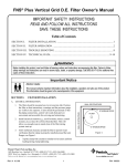
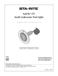
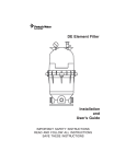
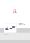
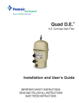
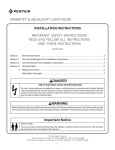
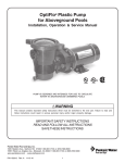
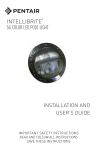
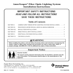
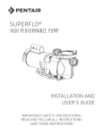
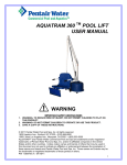
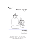
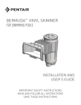
Clean & Clear ® Plus Cartridge Filters Owner's Manual IMPORTANT SAFETY INSTRUCTIONS READ AND FOLLOW ALL INSTRUCTIONS SAVE THESE INSTRUCTIONS Table of Contents SECTION I. FILTER INSTALLATION ................................................................................... 1 SECTION II. FILTER OPERATION AND CLEANING ........................................................... 3 SECTION III. TROUBLE SHOOTING ....................................................................................... 7 SECTION IV. TECHNICAL DATA ........................................................................................... 9 WARNING Before installing this product, read and follow all warning notices and instructions accompanying this filter. Failure to follow safety warnings and instructions can result in severe injury, death, or property damage. Call (800) 831-7133 for additional free copies of this manual. Important Notice Attention Installer. This manual contains important information about the installation, operation and safe use of this product. This information should be given to the owner/operator of this equipment. SECTION I. FILTER INSTALLATION A. GENERAL INFORMATION 1. The filter should be mounted on a level concrete slab. Position the filter so that instructions, warnings and the pressure gauge are visible to the operator. It also should be positioned so that the piping connections, control valve and drain port are convenient and accessible for servicing and winterizing. Pentair Water Pool and Spa, Inc. 1620 Hawkins Ave., Sanford, NC 27330• (800) 831-7133 • (919) 566-8000 10951 West Los Angeles Ave., Moorpark, CA 93021 • (800) 831-7133 • (805) 553-5000 Visit www.pentairpool.com or www.staritepool.com Rev. M 4-18-12 1 P/N 178558 2. Be certain to install electrical controls (e.g., on/off switches, timers, control systems, etc.) at least five (5) feet from the filter. This permits one to stand clear of the filter during system start up. 3. Allow sufficient clearance around the filter to permit visual verification that the clamp is properly installed around the tank flanges, see Figure A. a. 4. 5. Tap the clamp with a mallet or similar tool to ensure uniform loading during clamp tightening. Allow sufficient space above the filter to remove the filter lid for cleaning and servicing. This distance will vary with the model of filter you are using. See Table 1 for the required vertical clearance. Model No. Position the filter to safely direct water drainage. Rotate the High Flow™ manual air relief valve to safely direct purged air or water. Water discharged from an improperly positioned filter or valve can create an electrical hazard as well as damage property. Figure A. Table 1. P/N Size Vert. Clearance Req. CCP240 160310 240 sq. ft. 56 in. CCP320 160340 320 sq. ft. 62 in. CCP420 160301 420 sq. ft. 68 in. CCP520 160332 520 sq. ft. 74 in. WARNING Risk of electrical shock or electrocution. Position the filter and High Flow™ manual air relief valve to safely direct water drainage and purged air or water. Water discharged from an improperly positioned filter or valve can create an electrical hazard that can cause severe personal injury as well as damage property. 6. Make all plumbing connections in accordance with local plumbing and building codes. Filter plumbing connections are provided with an O-ring seal. If needed, use only a silicone base lubricant on the O-rings. Do not use pipe joint compound, glue or solvent on the bulkhead connections. NOTE To seal the valve connections, use thread seal tape, thread sealant or plumbing paste (non-petroleum base). 7. Remove the plug from the top of the filter lid and install the pressure gauge before use. 8. The maximum working pressure of this filter is 50 p.s.i. Never subject this filter to pressure in excess of this amount, even when conducting hydrostatic pressure tests. Pressures above 50 p.s.i. can cause the lid to be blown off, which can result in severe injury, death or property damage. When performing hydrostatic pressure tests or when testing for external leaks of the completed filtration and plumbing system, insure that the MAXIMUM PRESSURE that the filtration system will be subjected to DOES NOT EXCEED THE MAXIMUM WORKING PRESSURE OF ANY OF THE COMPONENTS CONTAINED WITHIN THE SYSTEM. In most cases, the maximum pressure will be stated on each component of the system. If doubt exists as to the pressure to which the system will be subjected, install an ASME P/N 178558 2 Rev. M 4-18-12 approved automatic Pressure Relief or Pressure Regulator in the circulation system for the lowest working pressure of any of the components in the system. SECTION II. FILTER OPERATION AND CLEANING WARNING THIS FILTER OPERATES UNDER HIGH PRESSURE. WHEN ANY PART OF THE CIRCULATING SYSTEM (e.g., FILTER LID, PUMP, FILTER, VALVES, ETC.) IS SERVICED, AIR CAN ENTER THE SYSTEM AND BECOME PRESSURIZED. PRESSURIZED AIR CAN CAUSE THE LID TO BLOW OFF WHICH CAN RESULT IN SEVERE INJURY, DEATH, OR PROPERTY DAMAGE. TO AVOID THIS POTENTIAL HAZARD, FOLLOW THESE INSTRUCTIONS. 1. BEFORE REPOSITIONING VALVES AND BEFORE BEGINNING THE ASSEMBLY, DISASSEMBLY, OR ADJUSTMENT OF THE LID OR ANY OTHER SERVICE OF THE CIRCULATING SYSTEM: (A) TURN THE PUMP OFF AND SHUT OFF ANY AUTOMATIC CONTROLS TO ASSURE THE SYSTEM IS NOT INADVERTENTLY STARTED DURING THE SERVICING. (B) OPEN AIR RELIEF VALVE, AND (C) WAIT UNTIL ALL PRESSURE IS RELIEVED - PRESSURE GAUGE MUST READ ZERO (0 psi). 2. WHENEVER INSTALLING THE FILTER LID, FOLLOW THE FILTER LID INSTALLATION INSTRUCTIONS EXACTLY. 3. ONCE SERVICE ON THE CIRCULATING SYSTEM IS COMPLETE, FOLLOW SYSTEM RESTART INSTRUCTIONS EXACTLY. 4. MAINTAIN CIRCULATION SYSTEM PROPERLY. REPLACE WORN OR DAMAGED PARTS IMMEDIATELY (e.g., lid, knob, pressure gauge, relief valve, O-rings, etc.) 5. BE SURE THAT THE FILTER IS PROPERLY MOUNTED AND POSITIONED ACCORDING TO INSTRUCTIONS PROVIDED. A. GENERAL INFORMATION 1. This filter operates under pressure. When clamped properly and operated without air in the circulating system, this filter will operate in a safe manner. 2. The maximum working pressure of this filter is 50 p.s.i. Never subject this filter to pressure in excess of this amount - even when conducting hydrostatic pressure tests. Pressures above 50 p.s.i. can cause the lid to be blown off, which can result in severe injury, death or property damage. When performing hydrostatic pressure tests or when testing for external leaks of the completed filtration and plumbing system, insure that the MAXIMUM PRESSURE that the filtration system will be subjected to DOES NOT EXCEED THE MAXIMUM WORKING PRESSURE OF ANY OF THE COMPONENTS CONTAINED WITHIN THE SYSTEM. In most cases, the maximum pressure will be stated on each component of the system. If doubt exists as to the pressure to which the system will be subjected, install an ASME approved automatic Pressure Relief or Pressure Regulator in the circulation system for the lowest working pressure of any of the components in the system. Rev. M 4-18-12 3 P/N 178558 3. The pressure gauge is the primary indicator of how the filter is operating. Maintain your pressure gauge in good working order. WARNING Your filter is a piece of machinery, do not tamper with it, attempt to disassemble it or otherwise adjust it unless you fully understand it's operation. Serious injury or death can occur if the equipment is improperly handled. Consult a pool service professional for maintenance and service assistance. 4. Clean your filter when pressure reads between 8-10 p.s.i. higher than the original starting pressure. Your filter pressure reading will increase as it removes dirt from your pool. However, this buildup of pressure will vary due to different bathing loads, temperature, weather conditions, etc. a. MY ORIGINAL STARTING PRESSURE IS ___________ psi (pounds per square inch). I SHOULD CLEAN THE FILTER CARTRIDGE ELEMENT AT __________ psi. NOTE For first time operation on new pools introduce into the system .75 pounds of diatomaceous earth per every 100 square feet of filter area (a one-pound coffee can equals .5 pounds of diatomaceous earth). Mix the diatomite with water and pour it into the skimmer after the pump is primed and the system is operating. This will enhance the filtration of your water. B. CLAMP INSTALLATION INSTRUCTIONS These instructions MUST BE FOLLOWED EXACTLY to prevent the lid from blowing off during system restart or later operation: 1. Perform the following procedures before working on any part of the circulating system (e.g., clamp, pump, filter, valves, etc.). a. Turn the pump off and shut off any automatic controls to ensure that the system is not inadvertently started during servicing. b. Open the High Flow™ manual air relief valve. c. Wait until all pressure is relieved. Never attempt to assemble, disassemble or adjust the filter clamp while there is any pressure in the filter. 2. Be certain the O-ring is in position in the lower tank half. Place the filter lid over the lower tank half sandwiching the O-ring in between. 3. Holding the ends of the filter clamp apart, position the center segment of the filter clamp over both upper and lower tank flanges. Bring the ends of the filter clamp together and insert the T-Bolt into the trunnion; see Figure B. 4. Using Figure B as a guide, place washer (large I.D.) and tension-indicating spring on the barrel nut. Place the second washer (small I.D.) on T-Bolt. Hand-tighten nut. Recheck filter clamp for proper seating on tank flanges. P/N 178558 Figure B. 4 Rev. M 4-18-12 5. 6. 7. Begin to tighten nut using a 7/8" wrench. Then tap around the outside of the filter clamp with a mallet (or similar tool) to insure uniform loading and proper seating of the clamp. Continue tapping and tightening until the spring coils touch each other. Do not tighten beyond this point. Follow the procedures in Section C, System Restart Instructions. The spring coils should be checked at least once per month to ensure that they continue to touch each other, indicating that the clamp is under sufficient tension. If coils fail to touch repeat Step B.5 in this section, above. C. SYSTEM RESTART INSTRUCTIONS WARNING THIS FILTER OPERATES UNDER HIGH PRESSURE. WHEN ANY PART OF THE CIRCULATING SYSTEM (e.g., CLAMP, PUMP, FILTER, VALVES, ETC.) IS SERVICED, AIR CAN ENTER THE SYSTEM AND BECOME PRESSURIZED. PRESSURIZED AIR CAN CAUSE THE LID TO BE BLOWN OFF WHICH CAN RESULT IN SEVERE INJURY, DEATH, OR PROPERTY DAMAGE. TO AVOID THIS POTENTIAL HAZARD, FOLLOW THESE INSTRUCTIONS. 1. 2. 3. 4. Open the High Flow™ manual air relief valve until it snaps into the full open position (this only requires a quarter turn counter-clockwise). Opening this valve rapidly releases air trapped in the filter. Stand clear of the filter tank, then start the pump. Close the High Flow™ manual air relief valve after a steady stream of water appears. The system is not working properly if either of the following conditions occur. a. A solid stream of water does not appear within 30 seconds after the pump's inlet basket fills with water. b. The pressure gauge indicates pressure before water outflow appears. If either condition exists, shut off the pump immediately, open valves in the water return line to relieve pressure, and clean the air relief valve, see Section F, Cleaning the High Flow™ manual air relief valve. If the problem persists, call (800) 831-7133 for assistance. D. CLEANING FILTER MANUALLY WARNING Operating the filter system without filter internal components installed can allow air to accumulate within the filter. Pressurized air can cause the lid to blow off which can result in severe injury, death or property damage. Always operate filter system with filter internal components installed. CAUTION The following information should be read carefully since it outlines the proper manner of care and operation for your filter system. As a result of following these instructions and taking the necessary preventative care, you can expect maximum efficiency and life from your filtration system. Rev. M 4-18-12 5 P/N 178558 1. Turn the pump off, shut off any automatic controls to ensure that the system is not inadvertently started during servicing. 2. Open the filter High Flow™ manual air relief valve (and the waste drain valve or plug, if your system has one). 3. Remove hair and lint strainer pot lid and clean basket. Replace basket and secure lid. 4. Disconnect air relief valve drain hose if installed. 5. Release tank clamp assembly and remove tank lid. 6. Remove top manifold and cartridge element separately. 7. Using a garden hose without a nozzle, direct water spray at cartridge element to dislodge and wash away accumulated foreign matter. Flush each cartridge inside and out. WARNING Please heed all manufacturers' posted instructions, warnings and cautions when using Baquacil® or Baqua® Clean. NOTE Special care must be taken when cleaning filter cartridges used in a swimming pool or spa using Baquacil® as a sanitizer. Because of the way Baquacil® works, the filter element must be cleaned more thoroughly and more frequently than in a chlorine system. If extreme care is not taken to completely remove all residue from the filter media a buildup will occur. This buildup will significantly shorten the life of the filter element. Baquacil® is a mild coagulant which combines bacterial cells as well as other small particles contributed by the environment, bathers, etc. into particles large enough to be trapped by the filter. In comparison with all other trapped contaminants in a typical pool or spa the amount of bacterial cells that are deposited on the filter is minimal. The resulting deposit is a gray sticky film which can only be removed with Baqua® Clean. If TSP or any TSP-type cleaner is used prior to stripping the film, the cleaner and the gray film will combine to form a gum-like substance. Once this occurs, the substance cannot be removed from the media and the filter cartridge must be replaced. 8. Lift bottom manifold out of the tank and flush off any debris. 9. Direct water spray to wash out the inside of the tank body. Water and debris will drain out through the open drain port. 10. Check gasket around outer lip of bottom plate. Gasket must be firmly and evenly set in place. Do not use petroleum base lubricants to avoid damage to the gasket. 11. Place bottom manifold, 4 cartridges, top manifold and air relief tube in place. Make sure the spring and standpipe assembly are retained on the top manifold. Ensure the air relief tube stays in an upright position. This is essential for the maximum air removal from inside the tank. 12. Be certain the O-ring is in position in the lower tank half. Press the filter lid over the lower tank half and sandwich the O-ring in between. 13. Replace tank top and carefully follow instructions in Section B, Clamp Installation Instructions. 14. Replace drain plug and reinstall air relief valve drain hose if used. P/N 178558 6 Rev. M 4-18-12 E. REPLACING FILTER CARTRIDGES Filter cartridge element life will vary with pool conditions such as bather load, wind, dust, etc. You can expect an average cartridge life of 3 years under normal conditions. 1. To replace cartridge element follow steps in Section D, Cleaning Filter, eliminating step D.7. F. CLEANING THE HIGH FLOW™ MANUAL AIR RELIEF VALVE 1. Turn the pump off and shut off any automatic controls to ensure that the system is not inadvertently started during servicing. 2. OPEN THE HIGH FLOW™ MANUAL AIR RELIEF VALVE UNTIL IT SNAPS INTO THE FULL OPEN POSITION, THEN WAIT UNTIL ALL PRESSURE IS RELIEVED. 3. With the relief valve attached to the filter tank, pull out the locking tabs and remove the valve stem and cover assembly with a counter-clockwise and lifting motion, see Figure C. 4. Clean debris from the valve stem and body. Verify that the filter tank's air passage is open by inserting a 5/16" drill bit through the valve body. Verify that the O-rings are in good condition, properly positioned, and lubricated with a silicone base lubricant. 5. Reinstall the valve stem and cover assembly with a downward and clockwise motion until it snaps into position. SECTION III. TROUBLE SHOOTING A. Air entering your filter is dangerous and can cause the lid to blow off. Correct any conditions in your filtration system that allow air to enter the system. 1. Some common ways to identify air entering the system: a. Low water level in pool or spa - skimmer is starving for water with pump running. Add water to pool or spa. b. Air bubbles or low water level in pump hair and lint pot are caused by: low water level, clogged skimmer basket, split suction cleaner hose, leak in pump hair and lint pot lid, or leak in pump suction line. c. Air bubbles coming out of water return lines into pool or spa with pump running, see items 1.a and 1.b of this section. d. Air is discharged from the air relief valve on top of the filter when the valve is opened with the pump running, see items 1.a and 1.b of this section, above. Figure C. B. Until the water initially put into the pool has been completely filtered, short filter cycles in between cleanings are normal. In most cases pool owners are dismayed by the undesirable color and appearance of water in a newly filled pool. Plaster dust can be responsible for short filter cycles, requiring frequent cleaning. Rev. M 4-18-12 7 P/N 178558 C. If pressure drops on gauge, check skimmer basket and pump basket first for debris. If the baskets are clean, shut off power to pump and turn off any automatic controls. Then turn motor shaft with your fingers. If it turns freely then the pump must be disassembled and the impeller checked to see if it is clogged. If it is not frozen or clogged then there is an obstruction in the line between the pool and the pump. D. The pressure gauge is an important part of the filter system. It is your primary indicator of how the system is operating. Maintain your pressure gauge in good working order. Check the operation of your pressure gauge in the following manner: 1. The pressure gauge should go to zero (0) when the system is turned off and pressure is relieved. 2. The pressure gauge should indicate pressure when the system is operating. 3. The pressure gauge should be readable and not damaged in any way. 4. Replace the pressure gauge if it is not meeting the requirements of items D.1 through D.2 of this section. P/N 178558 8 Rev. M 4-18-12 SECTION IV. TECHNICAL DATA A. FLOW RATES PRESSURE DROP vs FLOW 12 PRESSURE DROP (psi) 10 8 6 4 2 0 0 20 40 60 80 100 120 140 160 FLOW (gpm) Cle an & Cle ar® Plus Cartridge Filte rs Recommended Flow Rate Product # Model # Flow Rate GPM Turnover Capacity in Gallons Filter Area sq. ft. Vertical* Clearance Res. Comm. 6 hours 8 hours 12 hours 160310 CCP240 240 56 in. 90 90 32,400 43,200 64,800 160340 CCP320 320 62 in. 120 120 43,200 57,600 86,400 160301 CCP420 420 68 in. 150 150 54,000 72,000 108,000 160332 CCP520 520 74 in. 150 150 54,000 72,000 108,000 NOTE: Actual system flow will depend on plumbing size and other system components. * Required Clearance to remove filter elements. Rev. M 4-18-12 9 P/N 178558 B. CLEAN & CLEAR ® PLUS TANK ASSY. 1 2 3 20 4 5 7 6 8 23 9 13 10 8, 17 12 11 14 22 21 16 17 P/N 178558 15 18 19 10 Rev. M 4-18-12 B. CLEAN & CLEAR ® PLUS TANK ASSY., cont'd. Replacement Parts Item No. 1 Part No. Description Item No.Part No. Description Gauge, pressure, ¼ in. 12 195610 Washer, small I.D. 2 98209800 High Flow™ manual air relief valve (HFMARV) 12a 195611 Washer, large I.D. 13 194997 Nut, machined 3 98201200 Hose and retainer clips for HFMARV (Optional accy.) 13a 195612 Spring 4 4 5 190058 14 55035000 Baffle, bulkhead assy. 56636900 Spring, compression Ê 178616 14 Spring, compression 1 1 1 190039 Baffle, bulkhead assy. 15 86006900 O-ring, bulkhead, lower 59071000 Manifold, top assy. 5 170026 Manifold, top assy., 240 sq. ft. 5 170027 Manifold, top assy., 320 & 520 sq. ft. 16 98960311 Bulkhead union, (set) 16 271096 Bulkhead union, 1 ½ in. x 2 in. (set), white 16 270004 Bulkhead union, 1 ½ in. x 2 in. (set), black 6 R173572 Cartridge Element, 240 sq. ft., 4 req. 6 R173573 Cartridge Element, 320 sq. ft., 4 req. 6 R173574 Cartridge Element, 360 sq. ft., 4 req. 17 59019200 Pipe assy., outlet 6 R173575 Cartridge Element, 420 sq. ft., 4 req. aqua end caps 17 170035 Pipe assy., outlet/manifold, bottom 17 170036 Pipe assy., outlet 6 R173576 Cartridge Element, 420 sq. ft., 4 req. 18 51005000 O-ring for drain plug 6 R173577 Cartridge element, 520 sq. ft., 4 req. 19 86202000 Plug, 1-1/2 in. drain with O-ring 6 R173578 Cartridge element, 520 sq. ft., 4 req. 20 170023 Tank, lid assy., 240 sq. ft. 20 170024 Tank, lid assy., 320 sq. ft. 20 178552 Tank, lid assy., 360 sq. ft. 7 7 170030 Air bleed tube assy., 240 sq. ft. 55028500 Air bleed tube assy., 360, 420 sq. ft. 7 170029 Air bleed tube assy., 320 sq. ft. 20 178551 Tank, lid assy., 420 sq. ft. 7 170028 Air bleed tube assy., 420 sq. ft. 20 178581 Tank, lid assy., 420 sq. ft. 55028400 Air bleed tube assy., 500 sq. ft. 20 178550 Tank, lid assy., 500 sq. ft. 20 178582 Tank, lid assy., 520 sq. ft. 21 178559 Tank, bottom assy. 178578 Tank, bottom assy. 7 7 8 178583 Air bleed tube assy., 520 sq. ft. 56626800 Manifold, bottom 8 170035 Manifold, bottom/pipe assy., outlet 21 8 170040 Manifold, bottom 22 86006900 O-ring, bulkhead, upper 57000300 Gasket, bottom manifold 22 192320 O-ring, bulkhead, upper 10 39010200 O-ring, tank clamp (.470 O.D.) 23 195339 Ring, back-up 192019 Drain plug wrench 010126 Filter lid opener tool 9 11 190003 Clamp kit, tension control Rev. M 4-18-12 Before 11/98 After 11/98 Between 11/98 thru 12/00 After 12/00 After 3/03 After 10/04 Between 11/98 thru 10/04 11 P/N 178558 SAVE THESE INSTRUCTIONS © 2012 Pentair Water Pool and Spa, Inc. All rights reserved. 1620 Hawkins Ave., Sanford, NC 27330 • (800) 831-7133 • (919) 566-8000 10951 West Los Angeles Ave., Moorpark, CA 93021 • (800) 831-7133 • (805) 553-5000 This document is subject to change without notice. Trademarks and Disclaimers: Pentair Pool Products®, Because reliability matters most®, Clean & Clear®, and High Flow™, are trademarks and/ or registered trademarks of Pentair Water Pool and Spa, Inc. and/or its affiliated companies in the United States and/or other countries. Baquacil® and Baqua® are registered trademarks of Arch UK Biocides Limited. Unless noted, names and brands of others that may be used in this document are not used to indicate an affiliation or endorsement between the proprietors of these names and brands and Pentair Water Pool and Spa, Inc. Those names and brands may be the trademarks or registered trademarks of those parties or others. P/N 178558 12 Rev. M 4-18-12