1
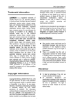
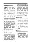
Compact Stagebox Installation and Operating Instructions Disclaimer The information in this document has been carefully checked and is believed to be accurate at the time of publication. However, no responsibility is taken by us for inaccuracies, errors, or omissions, nor is any liability assumed for any loss or damage resulting either directly or indirectly from use of the information contained within it. Prepared and edited by Studer Professional Audio GmbH Technical Documentation Riedthofstrasse 214 CH-8105 Regensdorf - Switzerland http://www.studer.ch Studer is a registered trade mark of Studer Professional Audio GmbH, Regensdorf Copyright by Studer Professional Audio GmbH Order no. 5031902 (0213) Subject to change without prior notice Safety Information For Your Own Safety and to Avoid Invalidation of the Warranty Please Read This Section Carefully • Read these instructions • Keep these instructions • Heed all warnings • Follow all instructions • Do not use this apparatus near water • Clean only with a dry cloth • Do not block any ventilation openings. Install in accordance with the manufacturer's instructions • Do not install near any heat sources such as radiators, heat registers, stoves, or other apparatus (including amplifiers) that produce heat • Do not defeat the safety purpose of a polarised or grounding type plug. A polarised plug has two blades with one wider than the other. A grounding type plug has two blades and a third grounding prong. The wide blade or the third prong are provided for your safety. If the provided plug does not fit into your outlet, consult an electrician for replacement of the obsolete outlet • Protect the power cord from being walked on or pinched particularly at plugs, convenience receptacles and the point where they exit from the apparatus • Only use attachments/accessories specified by the manufacturer • Use only with the cart, stand, tripod, bracket or table specified by the manufacturer, or sold with the apparatus. When a cart is used, use caution when moving the cart/apparatus combination to avoid injury from tip-over • Refer all servicing to qualified service personnel. Servicing is required when the apparatus has been damaged in any way, such as power-supply cord or plug is damaged, liquid has been spilled or objects fallen into the apparatus, the apparatus has been exposed to rain or moisture, does not operate normally, or has been dropped Note: It is recommended that all maintenance and service on the product should be carried out by Studer or its authorised agents. Studer cannot accept any liability whatsoever for any loss or damage caused by service, maintenance or repair by unauthorised personnel • WARNING: To reduce the risk of fire or electric shock, do not expose this apparatus to rain or moisture. Do not expose the apparatus to dripping or splashing and do not place objects filled with liquids, such as vases, on the apparatus • No naked flame sources, such as lighted candles, should be placed on the apparatus • Ventilation should not be impeded by covering the ventilation openings with items such as newspapers, table cloths, curtains etc. Warning: Do not use this apparatus in very dusty atmospheres, or in atmospheres containing flammable gases or chemicals • THIS APPARATUS MUST BE EARTHED. Under no circumstances should the safety earth be disconnected from the mains lead I Safety Information • • If any part of the mains cord set is damaged, the complete cord set should be replaced. The following information is for reference only. The wires in the mains lead are coloured in accordance with the following code: • Protective Earth (Ground): Green/Yellow (US: Green or Green/ Yellow) • Neutral: Blue (US: White) • Live (Hot): Brown (US: Black) As the colours of the wires in the mains lead may not correspond with the coloured markings identifying the terminals in your plug, proceed as follows: • The wire which is coloured Green and Yellow must be connected to the terminal in the plug which is marked with the letter E or by the earth symbol • The wire which is coloured Blue must be connected to the terminal in the plug which is marked with the letter N • The wire which is coloured Brown must be connected to the terminal in the plug which is marked with the letter L Ensure that these colour codes are followed carefully in the event of the plug being changed • The mains supply disconnect device is the mains plug. It must remain accessible so as to be readily operable when the apparatus is in use This unit is capable of operating over a range of mains voltages, as marked on the rear panel Note: This equipment has been tested and found to comply with the limits for a Class A digital device, pursuant to Part 15 of the FCC Rules. These limits are designed to provide reasonable protection against harmful interference when the equipment is operated in a commercial environment. This equipment generates, uses and can radiate radio frequency energy and, if not installed and used in accordance with the instruction manual, may cause harmful interference to radio communications. Operation of this equipment in a residential area is likely to cause harmful interference in which case the user will be required to correct the interference at his own expense. This Class A digital apparatus meets the requirements of the Canadian Interference-Causing Equipment Regulations. Cet appareil numérique de la Classe A respecte toutes les exigences du Règlement sur le matériel brouilleur du Canada. Working Safely With Sound Although your new console will not make any noise until you feed it signals, it has the capability to produce sounds that, when monitored through a monitor system or headphones can damage hearing over time.The table below is taken from the Occupational Safety & Health Administration directive on occupational noise exposure (1926.52): Permissible Noise Exposure: ! II Duration per day [h] 8 6 4 3 2 1.5 1 0.5 <0.25 Sound level [dBA, slow response] 90 92 95 97 100 102 105 110 115 Safety Information A1 Conforming to this directive will minimise the risk of hearing damage caused by long listening periods. A simple rule to follow is: The longer you listen, the lower the average volume should be. Please take care when working with your audio system – if you are manipulating controls which you don’t understand (which we all do when we are learning), make sure your monitoring level is turned down. Remember that your ears are the most important tool of your trade. Look after them, and they will look after you. Most importantly: Don’t be afraid to experiment to find out how each parameter affects the sound; this will extend your creativity and help you to get the best results. Safety Symbol Guide For your own safety and to avoid invalidation of the warranty, all text marked with these symbols should be read carefully. To reduce the risk of electric shock, do not remove covers. No user-serviceable parts inside. Refer servicing to qualified service personnel (i.e., persons having appropriate technical training and experience necessary to be aware of hazards to which they are exposed in performing a repair action, and of measures to minimize the danger of themselves). The lightning flash with arrowhead symbol is intended to alert the user to the presence of un-insulated ‘dangerous voltage’ within the product’s enclosure that may be of sufficient magnitude to constitute a risk of electric shock to persons. The exclamation mark within an equilateral triangle is intended to alert the user to the presence of important operating and maintenance (servicing) instructions in the literature accompanying the appliance. CAUTION RISK OF ELECTRIC SHOCK DO NOT OPEN ATTENTION RISQUE DE CHOC ELECTRIQUE NE PAS OUVRIR ACHTUNG GEFAHR: ELEKTRISCHER SCHLAG NICHT ÖFFNEN ! ! CLASS 1 LED PRODUCT CLASS 1 LASER PRODUCT A2 Headphones safety warnings contain important information and useful tips on headphone outputs and monitoring levels. Assemblies or sub-assemblies of this product can contain opto-electronic devices. As long as these devices comply with Class I of laser or LED products according to EN 60825-1:1994, they will not be expressly marked on the product. If a special design should be covered by a higher class of this standard, the device concerned will be marked directly on the assembly or sub-assembly in accordance with the above standard. First Aid In Case of Electric Shock: Warning! If the Person is Unconscious: Separate the person as quickly as possible from the electric power source: • By switching the equipment off, • By unplugging or disconnecting the mains cable, or • By pushing the person away from the power source, using dry insulating material (such as wood or plastic). • After having suffered an electric shock, always consult a doctor. Do not touch the person or his clothing before the power is turned off, otherwise you stand the risk of suffering an electric shock as well! • • • • • Lay the person down Turn him to one side Check the pulse Reanimate the person if respiration is poor Call for a doctor immediately. III Installation B General Installation Instructions Please consider besides these general instructions also any product-specific instructions in the ‘Installation’ chapter of this manual. B1Unpacking Check the equipment for any transport damage. If the unit is mechanically damaged, if liquids have been spilled or if objects have fallen into the unit, it must not be connected to the AC power outlet, or it must be immediately disconnected by unplugging the power cable. Repair must only be performed by trained personnel in accordance with the applicable regulations. B2 Installation Site Install the unit in a place where the following conditions are met: • The temperature and the relative humidity of the environment must be within the specified limits during operation of the unit. Relevant values are the ones at the air inlets of the unit (refer to Appendix 1). • Condensation must be avoided. If the unit is installed in a location with large variation of ambient temperature (e.g. in an OB-van), appropriate precautions must be taken before and after operation (refer to Appendix 1). • Unobstructed air flow is essential for proper operation. Air vents of the unit are a functional part of the design and must not be blocked in any way during operation (e.g. by objects placed upon them, placement of the unit on a soft surface, or installation of the unit within a rack or piece of furniture). • The unit must not be heated up by external sources of heat radiation (sunlight, spotlights). B3 Earthing and Power Supply Earthing of units with mains supply (class I equipment) is performed via the protective earth (PE) conductor integrated in the mains cable. Units with battery operation (< 60 V, class III equipment) must be earthed separately. Earthing the unit is one of the measures for protection against electrical shock hazard (dangerous body currents). Hazardous voltage may not only be caused by a defective power supply insulation, but may also be introduced by the connected audio or control cables. If the unit is installed with one or several external connections, its earthing must be provided during operation as well as while the unit is not operated. If the earthing connection can be interrupted, for example, by unplugging the mains plug of an external power supply unit, an additional, permanent earthing connection must be installed using the provided earth terminal. Avoid ground loops (hum loops) by keeping the loop surface as small as possible (by consequently guiding the earth conductors in a narrow, parallel way), and reduce the noise current flowing through the loop by inserting an additional impedance (common-mode choke). IV Installation / EMC Class I Equipment (Mains Operation) Should the equipment be delivered without a matching mains cable, the latter has to be prepared by a trained person using the attached female plug (IEC 320 / C13 or IEC 320 / C19) with respect to the applicable regulations in your country. Before connecting the equipment to the AC power outlet, check that the local line voltage matches the equipment rating (voltage, frequency) within the admissible tolerance. The equipment fuses must be rated in accordance with the specifications on the equipment. Equipment supplied with a 3-pole appliance inlet (protection conforming to class I equipment) must be connected to a 3-pole AC power outlet in such a way that the equipment cabinet is connected to the protective earth. For information on mains cable strain relief, please refer to Appendix 2. Female Plugs (IEC320), Front-Side View: L N L PE PE IEC 320 / C13 IEC 320 / C19 European Standard (CENELEC) Brown Blue Green/Yellow N North American Standard (NAS) L (Live) N (Neutral) PE (Protective Earth) Black White Green (or Green/Yellow) Class III Equipment (Battery Operation up to 60 VDC) Equipment of this protection class must be earthed using the provided earth terminal if one or more external signals are connected to the unit (see explanation at the beginning of this paragraph). B4 Electromagnetic Compatibility (EMC) The unit conforms to the protection requirements relevant to electromagnetic phenomena that are listed in guidelines 89/336/EC and FCC, part 15. • The electromagnetic interference generated by the unit is limited in such a way that other equipment and systems can be operated normally. • The unit is adequately protected against electromagnetic interference so that it can operate properly. The unit has been tested and conforms to the EMC standards of the specified electromagnetic environment, as listed in the following declaration. The limits of these standards ensure protection of the environment and corresponding noise immunity of the equipment with appropriate probability. However, a professional installation and integration within the system are imperative prerequisites for operation without EMC problems. For this purpose, the following measures must be followed: • Install the equipment in accordance with the operating instructions. Use the supplied accessories. • In the system and in the vicinity where the equipment is installed, use only components (systems, equipment) that also fulfill the EMC standards for the given environment. V EMC / Maintenance / ESD C • Use a system grounding concept that satisfies the safety requirements (class I equipment must be connected with a protective ground conductor) and that also takes into consideration the EMC requirements. When deciding between radial, surface, or combined grounding, the advantages and disadvantages should be carefully evaluated in each case. • Use shielded cables where shielding is specified. The connection of the shield to the corresponding connector terminal or housing should have a large surface and be corrosion-proof. Please note that a cable shield connected only single-ended can act as a transmitting or receiving antenna within the corresponding frequency range. • Avoid ground loops or reduce their adverse effects by keeping the loop surface as small as possible, and reduce the noise current flowing through the loop by inserting an additional impedance (e.g. common-mode choke). • Reduce electrostatic discharge (ESD) of persons by installing an appropriate floor covering (e.g. a carpet with permanent electrostatic filaments) and by keeping the relative humidity above 30%. Further measures (e.g. conducting floor) are usually unnecessary and only effective if used together with corresponding personal equipment. • When using equipment with touch-sensitive operator controls, please take care that the surrounding building structure allows for sufficient capacitive coupling of the operator. This coupling can be improved by an additional, conducting surface in the operator’s area, connected to the equipment housing (e.g. metal foil underneath the floor covering, carpet with conductive backing). Maintenance All air vents and openings for operating elements (faders, rotary knobs) must be checked on a regular basis, and cleaned in case of dust accumulation. For cleaning, a soft paint-brush or a vacuum cleaner is recommended. Cleaning the surfaces of the unit is performed with a soft, dry cloth or a soft brush. Persistent contamination can be treated with a cloth that is slightly humidified with a mild cleaning solution, such as dishwashing detergent. For cleaning display windows, commercially available computer/TV screen cleaners are suited. Use only a slightly damp (never wet) cloth. Never use any solvents for cleaning the exterior of the unit! Liquids must never be sprayed or poured on directly! For equipment-specific maintenance information please refer to the corresponding chapter in the operating and service manuals. D Electrostatic Discharge during Maintenance and Repair Caution: Observe the precautions for handling devices sensitive to electrostatic discharge! Many semiconductor components are sensitive to electrostatic discharge (ESD). The lifespan of assemblies containing such components can be drastically reduced by improper handling during maintenance and repair. Please observe the following rules when handling ESD sensitive components: • ESD sensitive components should only be stored and transported in the packing material specifically provided for this purpose. VI ESD / Repair • When performing a repair by replacing complete assemblies, the removed assembly must be sent back to the supplier in the same packing material in which the replacement assembly was shipped. If this should not be the case, any claim for a possible refund will be null and void. • Unpacked ESD sensitive components should only be handled in ESD protected areas (EPA, e.g. area for field service, repair or service bench) and only be touched by persons wearing a wristlet connected to the ground potential of the repair or service bench by a series resistor. The equipment to be repaired or serviced as well as all tools and electrically semi-conducting work, storage, and floor mats should also be connected to this ground potential. • The terminals of ESD sensitive components must not come in uncontrolled contact with electrostatically chargeable or metallic surfaces (voltage puncture, discharge shock hazard). • To prevent the components from undefined transient stress and possible damage due to inadmissible voltages or compensation currents, electrical connections should only be established or separated when the equipment is switched off and after any capacitor charges have decayed. E Repair By removing housing parts or shields, energized parts may be exposed. For this reason the following precautions must be observed: • Maintenance may only be performed by trained personnel in accordance with the applicable regulations. • The equipment must be switched off and disconnected from the AC power outlet before any housing parts are removed. • Even if the equipment is disconnected from the power outlet, parts with hazardous charges (e.g. capacitors, picture tubes) must not be touched until they have been properly discharged. Do not touch hot components (power semiconductors, heat sinks, etc.) before they have cooled off. • If maintenance is performed on a unit that is opened while being switched on, no un-insulated circuit components and metallic semiconductor housings must be touched, neither with bare hands nor with un-insulated tools. Certain components pose additional hazards: • Explosion hazard from lithium batteries, electrolytic capacitors and power semiconductors (Observe the component’s polarity. Do not short battery terminals. Replace batteries only by the same type). • Implosion hazard from evacuated display units. • Radiation hazard from laser units (non-ionizing), picture tubes (ionizing). • Caustic effect of display units (LCD) and components containing liquid electrolyte. Such components should only be handled by trained personnel who are properly protected (e.g. protection glasses, gloves). VII Repair / Disposal E1 SMD Components Studer has no commercially available SMD components in stock for service purposes. For repair, the corresponding devices have to be purchased locally. The specifications of special components can be found in the service manual. SMD components should only be replaced by skilled specialists using appropriate tools. No warranty claims will be accepted for circuit boards that have been damaged. Proper and improper SMD soldering joints are illustrated below. Copper Track SMD Component Soldering Iron Solder PCB Adhesive Dismounting Desoldering Iron Soldering Iron 1 2 3 Desolder Wick Desolder Wick Heat and Remove Mounting Cleaning Examples 1 2 Solder Ø 0.5...0.8 mm 3 Heating Time < 3 s per Side F Disposal Packing Materials Used Equipment The packing materials have been selected with environmental and disposal issues in mind. All packing material can be recycled. Recycling packing saves raw materials and reduces the volume of waste. If you need to dispose of the transport packing materials, please try to use recyclable means. VIII Used equipment contains valuable raw materials as well as materials that must be disposed of professionally. Please return your used equipment via an authorized specialist dealer or via the public waste disposal system, ensuring any material that can be recycled is. Please take care that your used equipment cannot be abused. To avoid abuse, delete sensitive data from any data storage media. After having disconnected your used equipment from the mains supply, make sure that the mains connector and the mains cable are made useless. Conformity G Declarations of Conformity This equipment complies with the EMC directives 2004/108/EC and LVD 2006/95/EC This product is approved to safety standards IEC 60065:2001 (Seventh Edition) +A1:2005 EN60065:2002 +AMD1:2006 + A11:2008 UL60065-07 CAN/CSA C22.2 No60065.03 + AMD01:2006 And EMC standards EN55103-1:2009 EN55103-2:2009 Warning: Any modification or changes made to this device, unless explicitly approved by the manufacturer, will invalidate the authorisation of this device. Operation of an unauthorised device is prohibited under Section 302 of the Communications act of 1934, as amended, and Subpart 1 of Part 2 of Chapter 47 of the Code of Federal Regulations. Note: This equipment has been tested and found to comply with the limits for a Class B digital device, pursuant to Part 15 of the FCC Rules. These limits are designed to provide reasonable protection against harmful interference in a residential installation. This equipment generates, uses and can radiate radio frequency energy and, if not installed and used in accordance with the instructions, may cause harmful interference to radio communications. However, there is no guarantee that interference will not occur in a particular installation. If this equipment does cause harmful interference to radio or television reception, which can be determined by turning the equipment off and on, the user is encouraged to try to correct the interference by one or more of the following measures: • Reorient or relocate the receiving antenna • Increase the separation between the equipment and the receiver • Connect the equipment into an outlet on a circuit different from that to which the receiver is connected. • Consult the dealer or an experienced radio/TV technician for help IX Appendix Appendix 1: Air Temperature and Humidity General Normal operation of the unit or system is warranted under the ambient conditions defined by EN 60721-3-3, set IE32, value 3K3. This standard consists of an extensive catalogue of parameters, the most important of which are: ambient temperature +5...+40 °C, relative humidity 5...85% (i.e., no formation of condensation or ice); absolute humidity 1...25 g/ m³; rate of temperature change < 0.5 °C/min. These parameters are dealt with in the following paragraphs. Under these conditions the unit or system starts and works without any problem. Beyond these specifications, possible problems are described below. Ambient Temperature Units and systems by Studer are generally designed for an ambient temperature range (i.e. temperature of the incoming air) of +5 °C to +40 °C. When rack mounting the units, the intended air flow and herewith adequate cooling must be provided. The following facts must be considered: • The admissible ambient temperature range for operation of the semiconductor components is 0 °C to +70 °C (commercial temperature range for operation). • The air flow through the installation must provide that the outgoing air is always cooler than 70 °C. • Average heat increase of the cooling air shall be about 20 K, allowing for an additional maximum 10 K increase at the hot components. • In order to dissipate 1 kW with this admissible average heat increase, an air flow of 2.65 m³/min is required. Example: A rack dissipating P = 800 W requires an air flow of 0.8 * 2.65 m³/min which corresponds to 2.12 m³/min. • If the cooling function of the installation must be monitored (e.g. for fan failure or illumination with spot lamps), the outgoing air temperature must be measured directly above the modules at several places within the rack. The trigger temperature of the sensors should be 65 °C to 70 °C. Frost and Dew The unsealed system parts (connector areas and semiconductor pins) allow for a minute formation of ice or frost. However, formation of dew visible to the naked eye will already lead to malfunctions. In practice, reliable operation can be expected in a temperature range above –15 °C, if the following general rule is considered for putting the cold system into operation: If the air within the system is cooled down, the relative humidity rises. If it reaches 100%, condensation will arise, usually in the boundary layer between the air and a cooler surface, together with formation of ice or dew at sensitive areas of the system (contacts, IC pins, etc.). Once internal condensation occurs, trouble-free operation cannot be guaranteed, independent of temperature. X Before putting into operation, the system must be checked for internal formation of condensation or ice. Only with a minute formation of ice, direct Appendix Example 1: Example 2: evaporation (sublimation) may be expected; otherwise the system must be heated and dried while switched off. A system without visible internal formation of ice or condensation should be heated up with its own heat dissipation, as homogeneously (and subsequently as slow) as possible; the ambient temperature should then always be lower than the one of the outgoing air. If it is absolutely necessary to operate the cold system immediately within warm ambient air, this air must be dehydrated. In such a case, the absolute humidity must be so low that the relative humidity, related to the coldest system surface, always remains below 100%. Ensure that the enclosed air is as dry as possible when powering off (i.e. before switching off in winter, aerate the room with cold, dry air, and remove humid objects such as clothes from the room). These relationships are visible from the following climatogram. For a controlled procedure, thermometer and hygrometer as well as a thermometer within the system will be required. An OB-van having an internal temperature of 20 °C and a relative humidity of 40% is switched off in the evening. If the temperature falls below +5 °C, the relative humidity will rise to 100% (7 g/m³); dew or ice will be forming. An OB-van is heated up in the morning with air of 20 °C and a relative humidity of 40%. On all parts being cooler than +5 °C, dew or ice will be forming. XI Appendix Appendix 2: Mains Connector Strain Relief For anchoring connectors without a mechanical lock (e.g. IEC mains connectors), we recommend the arrangement below: XII Procedure: The cable clamp shipped with your unit is auto-adhesive. For mounting please follow the rules below: • The surface to be adhered to must be clean, dry, and free from grease, oil, or other contaminants. Recommended application temperature range is +20 °C to +40 °C. • Remove the plastic protective backing from the rear side of the clamp and apply it firmly to the surface at the desired position. Allow as much time as possible for curing. The bond continues to develop for as long as 24 hours. • For improved stability, the clamp should be fixed with a screw. For this purpose, a self-tapping screw and an M4 bolt and nut are included. • Place the cable into the clamp as shown in the illustration above and firmly press down the internal top cover until the cable is fixed. Appendix Appendix 3: Software License Use of the software is subject to the Studer Professional Audio Software License Agreement set forth below. Using the software indicates your acceptance of this license agreement. If you do not accept these license terms, you are not authorized to use this software. Under the condition and within the scope of the following Terms and Conditions, Studer Professional Audio GmbH (hereinafter ‘Studer’) grants the right to use programs developed by Studer as well as those of third parties which have been installed by Studer on or within its products. References to the license programs shall be references to the newest release of a license program installed at the Customer’s site. Programs Covered by the Agreement License Programs of Studer Programs of Third Parties The following Terms and Conditions grant the right to use all programs of Studer that are part of the System and/or its options at the time of its delivery to the Customer, as well as the installation software on the original data disk and the accompanying documentation (‘License Material’). In this Agreement the word ‘Programs’ shall have the meaning of programs and data written in machine code. Using the software indicates your acceptance of this license agreement. If you do not accept these license terms, you are not authorized to use this software. Programs of third parties are all programs which constitute part of the System and/or its options at the time of delivery to the Customer but have not been developed by Studer. The following conditions are applicable to programs of third parties: • The right to use third parties’ programs is governed by the License Agreement attached hereto (if applicable), which is an integral part of this Agreement. The Customer shall sign any and all License Agreements for all further programs of third parties installed on the system. The Customer shall be deemed to have received all License Agreements upon delivery of the system and/or its options. • Studer shall accept no responsibility or liability for, and gives no warranties (express or implied) as to the programs of third parties. The Customer waives any and all claims versus Studer for any consequential damages, which might occur due to defects of these programs. Right of Use Principle Studer grants the Customer the non-exclusive right to use the License Material in one copy on the system and/or its options as laid down by the Sales Agreement concluded between the parties and all Terms and Conditions which shall be deemed to form and be read and construed as part of the Sales Agreement. This right is assignable according to the ‘Assignability’ paragraph hereinafter. Customized Configurations The Customer is not entitled to alter or develop further the License Material except within the expressly permitted configuration possibilities given by the software installed on the system or elsewhere. All altered programs, including but not limited to the products altered within the permitted configuration possibilities, are covered by this License Agreement. XIII Appendix Reverse Engineering Reverse engineering is only permitted with the express consent of Studer. The consent of Studer can be obtained but is not limited to the case in which the interface software can not be provided by Studer. In any case Studer has to be informed immediately upon complete or partial reverse engineering. Copying the License Material The Customer is entitled to make one copy of all or parts of the License Material as is necessary for the use according to this Agreement, namely for backup purposes. The Customer shall apply the copyright of Studer found on the License Material onto all copies made by him. Records shall be kept by the Customer regarding the amount of copies made and their place of keeping. The responsibility for the original program and all copies made lies with the Customer. Studer is entitled to check these records on first request. Copies not needed anymore have to be destroyed immediately. Disclosure of License Material The License Material is a business secret of Studer. The Customer shall not hand out or in any way give access to parts of or the complete License Material to third parties nor to publish any part of the License Material without prior written consent of Studer. The Customer shall protect the License Material and any copies made according to the paragraph above by appropriate defense measures against unauthorized access. This obligation of non-disclosure is a perpetual obligation. Third parties are entitled to have access to the License Material if they use the License Material at the Customer’s site in compliance with this Agreement. Under no circumstance are third parties entitled to have access to the installation software on the original data media. The Customer shall safeguard the original data media accordingly. Assignability The rights granted to the Customer according to this License Agreement shall only be assignable to a third party together with the transfer of the system and/or its options and after the prior written consent of Studer. Rights to License Material With the exception of the right of use granted by this License Agreement all proprietary rights to the License Material, especially the ownership and the intellectual property rights (such as but not limited to patents and copyright) remain with Studer even if alterations, customized changes or amendments have been made to the License Material. Studer’s proprietary rights are acknowledged by the Customer. The Customer shall undertake no infringements and make no claims of any patent, registered design, copyright, trade mark or trade name, or other intellectual property right. Warranty, Disclaimer, and Liability XIV For all issues not covered herewithin, refer to the ‘General Terms and Conditions of Sales and Delivery’ being part of the sales contract. Compact Stagebox CONTENTS 1General...............................................................................................................................................................3 1.1 Utilization for the Purpose Intended...........................................................................................................3 1.2 First Steps....................................................................................................................................................3 1.2.1 Unpacking and Inspection......................................................................................................................3 1.2.2Installation..............................................................................................................................................3 1.2.3 Adjustments, Repair, Cleaning...............................................................................................................3 1.3Features.......................................................................................................................................................4 1.4 Available I/O Modules................................................................................................................................5 1.5 D21m Expansion Slots................................................................................................................................5 2Details.................................................................................................................................................................5 3 2.1 Front / Rear View........................................................................................................................................6 2.2 AC Power Supply........................................................................................................................................6 2.3 Module Setup and Connector Details..........................................................................................................6 2.4 GPIO (General Purpose Inputs/Outputs).....................................................................................................8 Setup Examples................................................................................................................................................10 3.1 Compact Stagebox and Studer Consoles...................................................................................................10 3.2 Compact Stagebox and Studer Vista 1...................................................................................................... 11 3.2.1 Vista 1 Setup......................................................................................................................................... 11 3.2.2Connection...........................................................................................................................................13 4 I/O Module Replacement................................................................................................................................13 5 D21m I/O Card Installation............................................................................................................................15 6 Fan Air Filter Service......................................................................................................................................15 7 Technical Specifications............................................................................................................................................... 16 7.1Dimensions................................................................................................................................................17 Document generated: 12.02.13 SW V4.1 1 Compact Stagebox 2 SW V4.1 Document generated: 12.02.13 Compact Stagebox 1 General 1.1 Utilization for the Purpose Intended 1.2 1.2.1 The Studer Compact Stagebox is intended for professional use. It is presumed that the unit is operated only by trained personnel. Servicing is reserved to skilled technicians. The electrical connections may be connected only to the voltages and signals designated in this manual. First Steps Unpacking and Inspection Your new unit is shipped in a special packing which protects it against mechanical shock during transit. Care should be exercised when unpacking so that the surfaces do not get marred. Check the condition of the equipment for signs of shipping damage. If there should be any complaints you should immediately notify the forwarding agent and your nearest Studer distributor. Please retain the original packing material because it offers the best protection in case your equipment ever needs to be transported. 1.2.2 Installation Primary Voltage The power supply unit is auto-ranging; it can be used for voltages in a range of 100 to 240 VAC ±10%, 50 to 60 Hz. AC Supply Connection The attached female IEC 320/C13 cable socket has to be connected to an appropriate cable by a trained technician, respecting your local regulations. Refer to the ‘Installation, Operation, and Waste Disposal’ chapter at the beginning of this manual. Earthing This equipment must be earthed, due to the power input filter network being connected to earth. Some consideration must be given to the earthing arrangement of the system, at the center of which is the frame. The frame is earthed via the power supply. Ground loops may occur where signal processing equipment, patched to the frame, has its signal earth commoned to the equipment chassis. Temperature Regulations The unit must not be used in conditions of excessive heat or cold, near any source of moisture, in excessively humid environments, or in positions where it is likely to be subjected to vibration or dust. The ambient temperature range for normal operation of the unit is –5 to +45 °C. 1.2.3 Adjustments, Repair, Cleaning Danger All internal adjustments as well as repair work on this product must be performed by expert technicians! Replacing the Supply Unit The primary fuses are located within the power supply modules and cannot be changed. In case of failure, the complete power supply unit must be replaced. Please ask your nearest Studer representative. Cleaning Do not use any liquids to clean the exterior of the unit. A soft, dry cloth or brush will usually do. Document generated: 12.02.13 SW V4.1 3 Compact Stagebox 1.3 Features The Compact Stagebox is ideal for owners of Studer OnAir and Vista mixing consoles. It is a cost-effective possibility to extend the number of (remote) inputs and/or outputs by up to 48 analog inputs or outputs, for example. It features a high density of I/O connections in only four rack units. The modular unit is fully configurable, with a selection of 16-channel mic/line input modules, 16-channel analog line output modules, 16-channel AES/EBU in/out modules and 8-channel analog line/2×4-channel AES/EBU output modules. Recommended standard configuration: Compact Stagebox frame, 2 × HQ mic/line input modules, line output module, D21m MADI HD RJ45 card, blank panels for the D21m slots. It also offers two expansion slots for standard Studer D21m I/O cards. The D21m system is the I/O architecture for Studer digital mixing systems and allows connection to most popular digital formats, including CobraNet®, Aviom A-Net®16, EtherSound®, ADAT, Livewire® and RockNet®. A MADI recording interface may also be fitted to the expansion slots. When using optional D21m I/O cards, the total I/O count can be increased to 64 each. The Compact Stagebox uses the same I/O modules as found in the Studer OnAir 1500 and Vista 1 consoles. As a result, the combination offers more flexibility in sharing or moving modules and I/Os if required. When installing three mic/line input modules in the Compact Stagebox, then providing 48 mic/line inputs in total but no outputs, analog or AES outputs could still be obtained on D-Type connectors by installing D21m cards in the expansion slots. When installing cards in the expansion slots please note that the maximum input/output capacity of the Compact Stagebox is limited to 64 in/64 out by the MADI console link. The Compact Stagebox is connected to the host console using either Cat5 or optical-fibre MADI cables and also allows redundant MADI links. 4 SW V4.1 Document generated: 12.02.13 Compact Stagebox It comes complete with twin redundant power supplies, temperature-controlled, low-noise fan cooling, and full LED status monitoring. An eightchannel GPIO (general-purpose control input/output) interface is provided as well. 1.4 Available I/O Modules (Slots A, C, E) • 16 × HQ mic/line inputs • 16 × line outputs with DIP switch-selectable level • 8 × 2-ch AES/EBU inputs with SRC (sampling rate converters), plus 8 × 2-ch AES/EBU outputs • 4 × 2-ch AES/EBU outputs, plus 8 x line outputs with DIP switch-selectable level 1.5 D21m Expansion Slots (Slots K, L) The expansion slots may be used for one (dual-width) or two (single-width) Studer D21m I/O cards. Analog I/O • 8-channel line inputs (single-width) • 8-channel line outputs (single-width) • 4-channel mic/line inputs with 4 x direct outputs (single-width) 4-channel mic/line inputs with 4 x direct outputs (single-width) Digital I/O • 8 x 2-channel AES inputs and outputs (dual-width) • 64-channel MADI inputs and outputs for optical/multimode fibre (dualwidth) or Cat5 twisted-pair cable (dual-width) • 16-channel ADAT inputs and outputs (single-width) • 16-channel TDIF inputs and outputs (dual-width) • 16-channel Aviom A-Net® outputs (single-width) • 32-channel CobraNet® inputs and outputs (single-width) • 16-channel SDI embedder and/or deembedder (single-width) • 16-channel Dolby® E/Digital decoder (single-width) • 2 x 16-channel Livewire® inputs and outputs (single-width) • 64-channel RockNet® inputs and outputs (dual-width) • 64-channel EtherSound® inputs and outputs (dual-width). The EtherSound card is available from a third-party manufacturer/distributor only. Contact www.digigram.com for EtherSound® options. For more information on the D21m system please refer to the ‘D21m I/O System Operating Instructions’ document available from www.studer.ch in the ‘Downloads’ - ‘User Guides’ - ‘Studer D21m I/O System’ area. 2 Details The Compact Stagebox contains the D21m MADI HD card providing the connection to the console, three slots for input and/or output modules (A/C/E), and two slots for optional D21m I/O modules (K/L). These labeling conventions will also be used when patching the connectors to input channels or output busses of the console. The console requires the addition of a D21m MADI card (refer to chapter 3) for connecting to the Compact Stagebox. Document generated: 12.02.13 SW V4.1 5 Compact Stagebox 2.1 Front / Rear View 2.2 AC Power Supply 2.3 The Compact Stagebox is fitted with two power supplies, providing redundancy if required. The IEC power inlets are located on the rear panel. Both power supplies have an individual switch and provide a wide-range AC inlet, converting the input voltage to 24 VDC. For redundant operation, make sure that the two cables are connected to separate phases. Module Setup and Connector Details Analog Mic/Line Input Module The HQ mic/line input module handles 16 microphone or line level input signals, each input with gain adjustment (–11 to +75 dB for 0 dBFS), phantom power and high-pass filter, all controlled from the console. A red LED per input indicates when phantom power is active. For using this module in the Studer Compact Stagebox or in a Studer console (Vista 1 or OnAir 1500), jumper J1 must not be plugged. In order to change its setting, remove the module as described in chapter 4. 6 SW V4.1 Document generated: 12.02.13 Compact Stagebox Analog Line Output Module The line output module features 16 electronically balanced line outputs. A set of relays mutes the outputs in case of a power failure. The output level can be set with DIP switches for all outputs simultaneously (see below). Factory default setting is +15 dBu for 0 dBFS. In order to change the settings, remove the module as described in chapter 4. Factory Default: Ch 15-16 Ch 13-14 Ch 11-12 Ch 9-10 Ch 7-8 Ch 5-6 Ch 3-4 Ch1-2 Digital AES/EBU I/O Module The digital AES/EBU I/O module offers eight AES/EBU input and output pairs. A green LED per input pair indicates lock status. The inputs are equipped with sampling rate converters (SRC) that can be bypassed individually per pair with a DIP switch on the module. The factory default setting of the eight switch segments is OFF (enabled). In order to change the settings, remove the module as described in chapter 4. S1 Bypass AES/EBU+Analog Output Module The mixed analog/digital output module features eight electronically balanced analog line outputs and four AES/EBU output pairs. A set of relays mutes the analog outputs in case of a power failure. The level of the analog outputs can be set with DIP switches for all outputs simultaneously (similar to the picture above). Factory default setting is +15 dBu for 0 dBFS. In order to change the settings, remove the module as described in chapter 4. I/O Pin Assignments MIC/LINE IN (XLR 3 f) LINE OUT (XLR 3 m) AES/EBU IN / OUT (XLR 3 f / m) 2 3 1 Document generated: 12.02.13 1 3 2 Pin 1 2 3 SW V4.1 Signal (Input) Screen In + In – Signal (Output) Screen Out + Out – 7 Compact Stagebox LED Status Indicators The recessed RECONFIG key must be pressed after the card configuration has been changed (see the front panel drawing in chapter 2.1). RECONFIG D21m MADI HD Link Card ! ! Expansion Slots K and L 2.4 Status indicator LEDs are available for power rails, I/O modules, fan and temperature alarm. This card provides the audio and control connections to the console through either a Cat5 or an optical-fibre MADI link, depending on its type. The corresponding MADI card in the console transmits the clock for the Compact Stagebox down the MADI stream. The second input on the card can either be used to provide a redundant connection to the console, or to connect to a second system if two consoles are used for a monitor/FOH configuration. The MADI card indicates its clock status with the ‘LOCK’ LEDs on its front. An RS422 link output is also fitted, allowing transmission of RS422 data via a ‘pipeline’ within the MADI stream from a corresponding port on the console’s MADI card for remote RS422 control. For single cable operation: The front panel toggle switch must be set to either ‘MAIN’ or ‘AUX’, depending on which socket is being used. For dual cable (redundant) operation: The front panel toggle switch must be set to ‘RED’ mode. For additional information refer to the setup examples in chapter 3. These slots allow installing one or two additional, optional D21m input or output cards. For more information on the D21m system please refer to the ‘D21m I/O System Operating Instructions’ document available from www.studer.ch in the ‘Downloads’ - ‘User Guides’ - ‘Studer D21m I/O System’ area. GPIO (General Purpose Inputs/Outputs) Two 25-pin D-type connectors are provided, handling 8 GP (general purpose) control inputs and outputs, activated remotely from the console surface. GP inputs are on opto-isolators, GP outputs are on relay contacts. Control Inputs The control inputs (GPI Xa/b) are completely independent and electrically isolated. They may be used either with the internal +5 V DC supply voltage, or with external voltages of 5...24 V DC, regardless of the polarity (refer to the circuit examples below). GPI 1-8 (25-pin D-type, female, UNC 4-40 thread) 13 25 8 1 Solder/Crimp View (or Socket View) 14 Pin 1 2 3 4 5 6 7 8 9-13 SW V4.1 Signal ‘GPI 1-8’ GPI 1a GPI 2a GPI 3a GPI 4a GPI 5a GPI 6a GPI 7a GPI 8a GND (0 V) Pin 14 15 16 17 18 19 20 21 22-25 Signal ‘GPI 1-8’ GPI 1b GPI 2b GPI 3b GPI 4b GPI 5b GPI 6b GPI 7b GPI 8b VCC (+5 V / 600 mA max.) Document generated: 12.02.13 Compact Stagebox GP input examples: Ext. Supply 5...24 VDC Int. Supply (VCC) Desk Desk iLED Ext. Supply 5...24 VDC Desk iLED Ext. GND Int. GND Negative Common, Ext. Supply Desk iLED iLED Ext. GND Int. Supply (VCC) Negative Common, Int. Supply Int. GND Positive Common, Ext. Supply Positive Common, Int. Supply Control Outputs The control outputs (GPO Xa/b) are completely independent and electrically isolated relay contacts, closed if active. They may be used either with the internal +5 V DC supply voltage (VCC) and the internal ground, or with external voltages within the limits given in the table below. So when using an external supply, it is irrelevant wheter the load is connected between + or GND and one of the relay contacts, regardless of the polarity of the external supply voltage (refer to the circuit examples below). Switching Power Switching Voltage Switching Current Contact Resistance ! GPO Relay Contact Rating (max. Values) 62.5 VA / 30 W 50 V AC or DC 1A max. 100 mW at 6 V DC / 1 A The +5 V DC supply voltage and the ground (GND) terminals, together with the relay contacts, may be used to generate an output signal. Using an external supply together with the relay contacts is possible as well. The total current supplied by all VCC (+5 V DC) pins of the GPI / GPO connectors must not exceed 400 mA. GPO 1-8 (25-pin D-type, female, UNC 4-40 thread) 13 25 1 Solder/Crimp View (or Socket View) 14 Pin 1 2 3 4 5 6 7 8 9-13 Signal ‘GPO 1-8’ GPO 1a GPO 2a GPO 3a GPO 4a GPO 5a GPO 6a GPO 7a GPO 8a GND (0 V) Pin 14 15 16 17 18 19 20 21 22-25 Signal ‘GPO 1-8’ GPO 1b GPO 2b GPO 3b GPO 4b GPO 5b GPO 6b GPO 7b GPO 8b VCC (+5 V / 600 mA max.) GP output examples: Int. Supply (VCC) Ext. Supply Load (Lamp) Desk Ext. GND Ext. Supply SW V4.1 Desk Int. GND Document generated: 12.02.13 Load (Lamp) Int. Supply 9 Compact Stagebox 3 3.1 Setup Examples Compact Stagebox and Studer Consoles Note The example below shows the setup with the NanoSCore of a Studer OnAir 1500 console, but applies in a similar way with other Studer consoles, see the table below. Studer OnAir 1500 Core with optional MADI card in the D21m extension slot Mains In 24 VDC In Optical or RJ45 Cables depending on MADI card type Compact Stage Box Switch set to MAIN or AUX if using one cable, to RED if using 2 cables. Mains In 1 Mains In 2 Studer Console Stagebox support Stagebox connected to... Details OnAir 1500 OnAir 2500 SW V5.0 and up SW V5.0 and up D21m MADI card in Nano SCore integrated optical MADI I/O see drawing above see ‘Note’ below OnAir 3000 Vista 1 Vista 5-9 SW V4.8 and up SW V5.0 and up SW V4.703 and up (see chapter 3.2) D21m MADI card in D21m MADI card in D21m MADI card in SCore Live console extension slot SCore Live Select appropriate configuration (see chapter 3.2.1) Before inserting the MADI I/O card into your console or its DSP core, remember to power it down and unplug it from the AC supply. After powering the system on again, please note that the added inputs and outputs need to be patched to the console’s logical inputs and outputs. 10 Note The Studer OnAir 2500 console features no D21m card slot. Its built-in optical MADI interface may be used for the connection to the Compact Stagebox. To do so, the Compact Stagebox must be equipped with a MADI HD card with optical connectors. Up to 64 inputs and 56 outputs can be added in this way. SW V4.1 Document generated: 12.02.13 Compact Stagebox 3.2 Compact Stagebox and Studer Vista 1 Studer Vista 1 Console with optional MADI card in the D21m extension slot Optical or RJ45 Cables depending on MADI card type Mains In 1 Mains In 2 Compact Stage Box Switch set to MAIN or AUX if using one cable, to RED if using 2 cables. Mains In 1 Mains In 2 Note 3.2.1 The Studer Vista 1 console needs a D21m MADI card installed for connecting to the Compact Stagebox. The integrated optical MADI interface cannot be used for this connection since it offers no support for the MADI-embedded input control signals. It is intended as a recording interface only. Vista 1 Setup The number of input and output ports on Vista 1 is defined in the DSP session configuration. The Vista 1 comes with several factory-set configuration templates with a default of 32 input ports and 16 output ports for the D21m card slots. These I/O port configurations are optimized for the use with a MADI I/O card to connect to the Studer Compact Stagebox. The Compact Stagebox I/O ports have the following device labels predefined: Input ports Stagebox 1 - Stagebox 32 Output ports Stage Out 1 - Stage Out 16 Document generated: 12.02.13 Before inserting the MADI I/O card into your Vista 1, remember to power the console down and unplug it from the AC supply. Note: The DIP switches of the MADI card must be set to match the actual number of channels provided from and to the Stagebox. For details, please refer to the ‘D21m I/O System Operating Instructions’ document, available either from www.studer.ch in the ‘Downloads’ - ‘User Guides’ - ‘Studer D21m I/O System’ area, or on the product disc (CD or DVD) shipped with your console. SW V4.1 11 Compact Stagebox Remove the blank panels and insert the MADI card. After powering the console up again and starting the Vista application, the recessed RECONFIG button must be pressed. A message window may appear in the Vista application. Click on the Ok button and wait for a couple of seconds until a new message window I/O Hardware change detected – Wait for default I/O setup to reappear? appears. There are three option buttons: Ok, Use for this session only, and Store as new default. Click on Store as new default. Again, after waiting for a few seconds the Surveyor icon will become green and the added card will be visible in the Surveyor details. The MADI card is now ready to be used. Once the local MADI card has been added to the desk as explained above, it will be displayed in the console’s Surveyor window. After connecting and powering up the Stagebox, it will automatically appear in the Surveyor as an additional I/O entity named Remotebox. Should yellow triangles appear in the dialog above, re-start the Vista application on the console. 12 SW V4.1 Document generated: 12.02.13 Compact Stagebox 3.2.2 Connection Note: The DIP switches on the MADI HD card in the Compact Stagebox must be set to match the actual number of channels provided from and to the Stagebox. For details, please refer to chapter 4 below and the ‘D21m I/O System Operating Instructions’ document, available either from www.studer.ch in the ‘Downloads’ - ‘User Guides’ - ‘Studer D21m I/O System’ area, or on the product disc (CD or DVD) shipped with your console. Vista 1 is predefined for use with a Studer Compact Stagebox featuring 32 mic/line inputs and 16 line outputs. Template titles for these configurations are, for example, ‘Vista1 Mono’, ‘Vista1 Stereo’, ‘Vista1 Surround’, ‘Vista1 FOH’, etc. If the number of I/O ports required by the Stagebox should exceed 32/16, it is recommended to use one of the DSP session configurations having 64/64 I/O available for the D21m extension slot: ‘Vista1 Monod21’, ‘Vista1 Stereod21’, ‘Vista1 Surroundd21’, etc. Information on how to select DSP configurations can be found in the Vista 1 operating instructions manual. 4 When now patching microphone inputs from the Compact Stagebox to any of the console’s input channels and pressing the GLOBAL VIEW - MIC CTRL key on the desk, the microphone preamp control parameters appear on the Vistonics screen. Input gain, 48 V phantom power and the high-pass (low-cut) filter can now be controlled remotely from the desk. I/O Module Replacement Safety For adjustments or replacing an input or output module, first switch the Compact Stagebox off and unplug the AC supply cable(s). Observe the precautions for handling devices sensitive to electrostatic discharge; also refer to chapter D at the beginning of this manual. • When using an HQ mic/line input module in the Studer Compact Stagebox, jumper J1 must not be plugged. • When using a line output module in the Studer Compact Stagebox, the output level of the analog line output module may be selected according to your preferences between +6 and +24 dBu for 0 dBFS (factory default setting: +15 dBu for 0 dBFS). This setting is valid for all outputs simultaneously. Factory Default: Document generated: 12.02.13 SW V4.1 13 Compact Stagebox Procedure • For all screws in question a no. 2.5 Allen screwdriver is used. • Remove the top cover of the Compact Stagebox (2 countersunk screws M4×8 on top, 13 screws M4×6 around the upper edge). • Unplug the module’s flat cable(s) from the backplane PCB, and the supply loom from the module. • Remove the 4 screws M4×6 at the module’s edges. Remove the module. This may require some pressure from the rear of the module. • Insert the new module and fix it with the 4 screws. Connect the flat cable(s) to the corresponding socket on the backplane PCB (for correct connection refer to the illustration below). • Connect the supply loom to the module. Supply looms are identical for input and output modules, no particular order has to be followed when reconnecting them. Similar to supply connections within a PC, there is one connector more than modules to feed; the fourth connector is not used. • For fixing the top cover it is recommended to first insert all screws only by a few turns into their threads before tightening them. • Connect the Compact Stagebox to the AC supply again, switch it on and press the recessed RECONFIG key with a small tool such as the Allen screwdriver used before. • Remember that the new input/output count needs to be configured in your console’s I/O mapping. Please refer to its operating instructions. Input Modules Output Modules TOP (A) TOP (A) MIDDLE (C) MIDDLE (C) BOTTOM (E) BOTTOM (E) The three I/O module slots are labeled A, C and E from top to bottom; they correspond to the connectors of the backplane PCB shown in the illustration above. There are three sockets on the left for input modules, and another three on the right for output modules. Modules must be connected to the corresponding socket in order to have a correct assignment of input and/or output channels. 14 ! When installing or removing an AES/EBU I/O module, the procedure is slightly different, since this module features inputs and outputs. For this reason, two flat cables need to be connected or disconnected. The connectors on the module are: P1 for outputs and P2 for inputs (the PCB silkscreen print SW V4.1 Document generated: 12.02.13 Compact Stagebox shows corresponding arrows), which means that the cables must be crossed over for connecting it to the backplane of the Compact Stagebox. In a common configuration (two mic/line input modules in slots A and C, one line output module in slot E) the modules are connected as follows: • Input (slot A) è top connector on the left side of the backplane (P2) • Input (slot C) è middle connector on the left side of the backplane (P13) • Output (slot E) è bottom connector on the right side of the backplane (P20). If someone wanted now to replace the output module in slot E by one more mic/line input module (all three modules will be inputs then), they are connected as follows: • Input (slot A) è top connector on the left side of the backplane (P2) • Input (slot C) è middle connector on the left side of the backplane (P13) • Added input module (slot E) è bottom connector on the left side of the backplane (P19). 5 Supply looms are identical for input and output modules. No particular order has to be followed when reconnecting them. Similar to the PC-internal supply connections for additional harddisk or , there is one connector more than modules to feed; this connector is not used. D21m I/O Card Installation Safety • In order to insert or replace a D21m input or output card, first switch the Compact Stagebox OFF and unplug the AC supply cable(s). Observe the precautions for handling devices sensitive to electrostatic discharge – refer to chapter D at the beginning of this manual. • In the K and L slots, one or two additional D21m input or output cards may be installed. • Remove the blank panel or the card to be replaced using a no. 2 screwdriver. Carefully insert the D21m cardso that its edge connector fits into its counterpart on the backplane. Re-tighten the screws. • Connect the Compact Stagebox to the AC supply again, switch it on and press the RECONFIG button with a small tool (e.g. a size 2.5 Allen screwdriver). • Remember that the new input/output count needs to be configured in your console’s I/O mapping. Please refer to its user guide. For more information on the D21m system please refer to the ‘D21m I/O System Operating Instructions’ document available from www.studer.ch in the ‘Downloads’ - ‘User Guides’ - ‘Studer D21m I/O System’ area. 6 Fan Air Filter Service • For cleaning or replacing the air filter mat, just pull the black guard frame away from the fan air inlet and remove the filter mat. • In order to clean the filter mat, thoroughly rinse it in warm water. Let it dry completely before reinstalling it. Spare air filter/air inlet grill set: Order no. C072.030003 Document generated: 12.02.13 SW V4.1 15 Compact Stagebox 7 Technical Specifications HQ Mic / Line Inputs General Conditions: Impedance Gain Maximum Input Level Frequency Response THD + Noise Equivalent Input Noise / Noise Figure (NF) Common Mode Rejection Ratio (CMRR) Crosstalk Switchable High-Pass Filter (subject to change without prior notice) Conditions / Details Value Gain setting 15 dBu 0 dBFS unless otherwise noted. (electronically balanced) for 0 dBFS (adjustable in steps of 1 dB) –11 dB gain, Rsource = 600 Ω 0 dB gain, Rsource = 150 W 20 Hz to 20 kHz, 40 dB gain 30 Hz to 20 kHz, 40 dB gain 1 kHz, –1 dBFS 1 kHz, –9 dBFS (nominal level) 20 Hz to 20 kHz, –30 dBFS Ri = 200 W, gain ≥ 60 dB 30 Hz to 20 kHz, all gain settings 1 kHz, –11 dB to +26 dB gain 1 kHz (nominal level) 3.6 kW –11 to +75 dB +26 dBu +15 dBu +0 / –0.6 dB +0 / –0.3 dB ≤ –87 dB ≤ –94 dB < –102 dBFS –127.6 dBu / NF ≤ 2 > 46 dB 60 dB typ. ≤ –100 dB 75 Hz 12 samples 250 μs @ 48 kHz Input Delay Line Outputs Impedance Frequency Response THD + Noise Crosstalk Output Level Conditions / Details Value (electronically balanced) 20 Hz to 20 kHz –1 dBFS, 1 kHz –30 dBFS, 20 Hz to 20 kHz 1 kHz RL ≥ 600 W; globally adjustable with hardware switches (steps: +24, +22, +20, +18, +15, +12, +9, +6 dBu) 50 Ω +0 dB / –0.3 dB –90 dB –103 dB –115 dB +6 to +24 dBm for 0 dBFS 10.4 samples 217 μs @ 48 kHz Output Delay AES / EBU Inputs Impedance Sensitivity SRC Range Conditions / Details rS_IN > rS_OUT : D = SRC Delay (if active) AES / EBU Outputs Impedance Level Power Supply Value 32 16 + [s] rS_IN rS_OUT 110 W min. 0.2 VRMS 22-108 kHz 48 [s] rS_IN < rS_OUT : D = rS_IN Conditions / Details Value 110 W 4.0 VRMS into 110 W Conditions / Details Power Consumption Auto-ranging, with power factor correction (PFC); EN/UL approved. 2 power supply units + inlets provided for redundancy. (depending on installed modules/cards) Ambient Conditions Details Primary Input Voltage Range Operating Temperature Range* Relative Humidity* non-condensing * Also refer to ‘Appendix 1: Air Temperature and Humidity’ on page X at the beginning of this manual Weight Studer Compact Stagebox, typical configuration 16 2 × mic/line input modules, 1 × line output module, 1 × D21m MADI HD card, no D21m I/O cards (2 blank panels only) SW V4.1 Value 100 to 240 V AC ± 10% 50 to 60 Hz max. 300 W Value –5 to 45 °C / 23 to 113 °F 95% Value 10 kg / 22 lbs Document generated: 12.02.13 Compact Stagebox Dimensions 177 mm / 7” (4 HU) 7.1 483 mm / 19” 2 mm / 0.1” 42 mm 1.7” Document generated: 12.02.13 363 mm / 14.3” SW V4.1 17 Compact Stagebox 18 SW V4.1 Document generated: 12.02.13