1
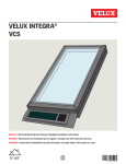
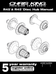
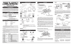
PEDESTAL OVERHAUL INTRODUCTION A properly greased labyrinth seal will help prevent dust and water damage to the pedestal bearing oil supply and shaft seal area. Properly greased and oiled pedestals rarely require an overhaul. Oil seeping out from the upper or lower seals or sideways shaft movement may be an indication that the pedestal needs a partial or complete overhaul. bearing industry. Measurement procedures can be found in some bearing catalogs. SPECIAL TOOLS Eyebolts for lifting Hydraulic press with a pressure gauge and blocks Table with a hole in it and a work stand to which the pedestal housing can be bolted. A work stand that rotates along a horizontal axis is ideal. AN-NUT socket Long Feeler gauges for checking RIC Bearing Heater Sideways shaft movement If it is determined the pedestal needs a complete rebuild, it should be removed from the crusher to a clean work area. Refer to the parts manual for specific part identification. Never replace only one bearing and never reuse a seal or O-ring. Some assembly steps require heating the bearings or pedestal housing to allow for part assembly with an interference fit. Heated parts need sufficient time to cool so they do not separate during subsequent assembly steps; and before checking bearing tolerances (RIC). Some of the tools for a pedestal overhaul Seal plate removal can be done by hand on a small pedestal. Use lifting eyes and a hoist to remove the seal plates on large pedestals. Refer to the BELT MAINTENANCE AND REPLACEMENT and SHEAVE REPLACEMENT sections where appropriate. Some knowledge of bearing clearances is needed to properly diagnose and rebuild a pedestal. Specifically, the Radial Internal Clearance, or RIC must be measured and compared to tabulated values. The RIC and its measurements are standardized in the Pedestal work stand 71 041601 PEDESTAL OVERHAUL REPLACEMENT PARTS Upper Dust Seal Upper and Lower Oil Seals Upper and Lower O-Rings the hub, carefully heat the hub and strike the hub with an aluminum or brass block held against the hub. Be careful not to damage the hub surface or lifting mechanism. The hub should separate from the main shaft. Relieve the lift pressure and remove the lock nut and hub. Alignment Tube O-Rings Upper and Lower Bearings AN Lockwashers Carefully strike a block held against the hub PRELIMINARY DISASSEMBLY AND DIAGNOSIS Replacement parts HUB REMOVAL 1. Remove SuperChipper™ or impeller table from the hub and set aside. Wash the crusher and pedestal to remove dirt. 2. Bend the lockwasher tab out of the slot in the upper lock nut and use a blunt nosed drift and a heavy hammer to remove the locknut, then remove the lockwasher. 3. Unthread the remaining locknut until it is even with the top of the shaft threads. Leave the locknut in this position to prevent the hub from coming off the shaft or damaging the threads when it separates from the shaft. 4. Insert three lifting eyes into the hub and use a lift or hoist to take the slack out of the chains and exert an upward force on the hub. 5. If it is necessary, place bottle jacks under the hub to help lift and remove hub from off of the pedestal shaft. Once the upward pressure is placed on 72 1. Remove the six cap screws in the upper seal plate. Use lifting eyes (if equipped with them) to raise the seal plate off the pedestal housing. Note: Recent model crushers have 2 set screws in the seal plate. Tighten the set screws in equal increments to separate the seal plate from the pedestal housing. To install the lifting eyes, the set screws must be completely removed and the eyes are then threaded into the vacant holes. ing. Avoid scratching the seal surface. Do not pry the seal plate off the pedestal hous- PEDESTAL OVERHAUL PEDESTAL REMOVAL If the pedestal needs rebuilding, it must be removed from the crusher now. Otherwise, follow the PEDESTAL ASSEMBLY procedure to install the upper seal plate with new seals. 1. Clean or wash the pedestal sheave. Remove pedestal shroud and remove material from the pedestal bottom. Make sure the sheave bolt hole threads are clean. 2. Remove the oil and grease lines from the pedestal underside. Seal the loose hose ends to keep dirt out. Underside of the upper seal plate 2. Observe the underside of the seal plate. Look for oil getting past the O-ring. Look for dirt in between the seals. 3. Remove the upper dust and grease seal and the oil seal O-ring from the seal plate. Check the rubber on the seals and the O-ring for damage. 4. Inspect the mating surfaces between the upper seal plate and pedestal housing for dirt outside the oil seal O-ring, or any damage where the plates meet. 5. Inspect the shaft where the upper dust and grease seal and oil seal rubber gaskets make contact. A groove in the shaft indicates lack of oil or grease. If this groove is deeper than .004", the shaft needs to be repaired or replaced. Oil and grease connections at pedestal 3. Remove the bolts which secure the pedestal to the crusher channel. 4. Install a lifting eyebolt in the end of pedestal shaft and lift the assembly, including the drive sheave, out of the crusher. 5. Wash the pedestal assembly to remove dirt and foreign material from the sides or seal plates. 6. Bolt the pedestal assembly to a frame or table for further disassembly. COMPLETE PEDESTAL DISASSEMBLY Grooves in shaft caused by seals While all crusher drivetrains are unique, in some cases the crusher may have a larger diameter sheave than the hole in the crusher. Be extremely careful when removing the sheave, especially if the pedestal is in the crusher. A strap or chain arrangement should 73 PEDESTAL OVERHAUL be used as a safety to catch the sheave and bushing 2. Clean out the oil and grease passages first with solin the event they should unexpectedly slip off the vent and then with compressed air. It is usually not shaft. necessary to remove any of the pipe plugs in the lower seal plate mounting surface. If you do remove 1. Measure the bushing distance from the end of the any plugs, clean them thoroughly and replace them pedestal shaft. You will need this measurement below the machined surface using pipe thread sealwhen reinstalling the sheave / bushing. ant. 2. Remove the sheave. (Refer to Sheave Replace3. Measure the upper and lower bearing bores in the ment section.) pedestal housing and the shaft diameter at the upper 3. Remove the sheave bushing. bearing area. They should meet the factory specifications listed in this manual. 4. Tap the key out of the shaft keyway. 4. Inspect the shaft taper where the lower bearing fits. 5. Orient the pedestal assembly upside down in the It should be clean and smooth. work area for disassembly. 6. Remove the lower seal plate cap screws and use lifting eyes (if needed) to remove the seal plate from the pedestal housing. 7. Remove the lower oil seal and O-ring from the seal plate. 8. Inspect the seal plate and pedestal mating surfaces for damage. 9. Remove the lower bearing shaft lock nuts and lockwasher. (Same procedure as #2 in Hub Removal.) 10. Orient the pedestal upside down in a hydraulic press and push the main shaft out of the housing. Frequently the upper bearing will come out with the shaft. If the bearing remains in the housing, go ahead and remove the shaft and use a (bearing) block or heat to remove the bearing from the housing. 11. If the upper bearing is still attached to the shaft, remove it using heat or a hydraulic press. Measuring a bearing bore CRUSHER MODEL Upper Bore 35 54 70 128 160 175 5.9045 7.0852 8.4625 9.0530 12.5960 12.5960 12.5960 12.5960 5.9050 7.0842 8.4635 9.0535 12.5965 12.5965 12.5965 12.5965 Min (in) 5.9052 7.4794 7.4805 9.4495 9.0534 9.0534 11.4162 11.4162 Max (in) 5.9057 7.4805 7.4810 9.4500 9.0539 9.0539 11.4173 11.4173 Min (in) 3.3470 3.9375 4.7255 5.1190 5.9064 5.9064 5.9064 5.9064 Max (in) 3.3475 3.9380 4.7260 5.1195 5.9069 5.9069 5.9069 5.9069 Min (in) 12 Max (in) 80 96 Lower Bore Shaft Diameter 12. The lower bearing should easily separate from the pedestal housing. If it does not, gently tap it out with a block of wood and a plastic or rubber mallet. Pedestal and Bearing Bore Specifications CLEAN AND INSPECT THE PEDESTAL ASSEMBLY 1. Clean the shaft, seal plates, and pedestal housing with solvent or similar cleaner. 74 PEDESTAL ASSEMBLY 1. Heat the upper bearing to 50°F above the temperature of the shaft (be careful not to overheat the bearing.) PEDESTAL OVERHAUL • DANGER • DO NOT WELD REPAIR A PEDESTAL MAIN SHAFT! 2. Screw a lifting eyebolt into the top of the shaft. Lower the shaft into the bearing (Using some WD40 or other lubricant can help with inserting the shaft.) (A table with a hole in it works well for this procedure.) Allow the assembly to cool. 3. First heat the entire pedestal evenly, then heat the pedestal region which surrounds the upper bearing bore until the inside diameter just exceeds the Maximum Upper Bore dimension given in the preceding table. 4. Suspend the shaft and bearing above the upright pedestal. Lubricate the outside of the bearing with WD-40 or a similar lubricant. 5. Lower the shaft/upper bearing assembly into the bore. Seat the bearing in the bore by tapping it lightly with a brass or plastic mallet. Allow the assembly to cool slightly (5min), so the upper bore can retain the bearing and shaft. 7. Slide the tapered bore lower bearing (large end of taper first) over the shaft. Tap the inside bearing race with a brass drift or punch, securely seating it against the tapered shaft section. Orient the pedestal sideways. 8. Thread one of the lower bearing shaft lock nuts with the flat side facing the bearing on the shaft. This will prevent the bearing from slipping off the shaft. At this point, the entire pedestal assembly needs to cool down completely (overnight would be best). Once the pedestal has cooled, tighten the nut and check the tapered bore bearing RIC. As the nut is tightened, the RIC decreases due to the expansion of the inner race on the taper. Do not overtighten. If you exceed the minimum RIC, disassemble the pedestal and start over. 9. Install the lockwasher with the concave side away from the pedestal housing. The inner tooth slides in the slot machined into shaft threads. 10. Thread on the remaining large lock nut with the flat side away from the pedestal housing. Manually tighten it with a hammer and punch, or AN socket 11. Bend a tab on the lockwasher into one of the four cutouts on the nut. This locks the nuts in place. C H E C K Lowering shaft/bearing into pedestal 6. Orient the pedestal assembly upside down so the lower bearing bore is accessible. Locknuts/lockwasher/bent tab 75 PEDESTAL OVERHAUL UPPER BEARING CLEARANCE 1. Leave the pedestal assembly in a horizontal position. 2. Check the upper bearing Radial Internal Clearance (RIC) by inserting a long feeler gauge between the rollers and the outer race. With the shaft in the horizontal position, the clearance must be measured over both rows of rollers. Slide the feeler gauge in a saw-like motion between the roller and the outer race. The clearance should be within the specifications listed below: From this example the Radial Internal Clearance before mounting is .0037min .0047max. Use a long blade feeler gauge set to get the actual measurement of Radial Internal Clearance across both bearings. Once the actual measurement is recorded, subtract the Reduction Radial Internal Clearance min. & max. to get a range of clearance. Example: Actual measurement from feeler gauge is .0040mm. (.0040mm) - (.0016mm (max))= .0024mm (how loose) (.0040mm)-(.0020mm(max))=.0020mm (how tight) Maximum .0072 inches INSTALL UPPER SEAL(S) AND SEAL PLATE Optimum .0055 inches Minimum .0038 inches A grease seal and O-ring are installed in the upper seal plate. The grease seal provides a seal between the seal plate and shaft. The O-ring provides the seal between the seal plate and the pedestal housing. Larger crushers also have a dust seal which installs on top of the grease seal. 3. If the clearance is too loose the pedestal housing or shaft are out of tolerance and need to be replaced. LOWER BEARING CLEARANCE GREASE SEAL Here are the clearance specifications for the lower bearings, according to the crusher model you have: Nominal bearing bore mm d over incl. 24 30 40 50 65 80 100 120 140 160 180 200 225 250 280 30 40 50 65 80 100 120 140 160 180 200 225 250 280 315 Radial Internal Clearance Before Mounting min .0018 .0020 .0024 .0030 .0037 .0043 .0053 .0063 .0071 .0079 .0087 .0098 .0106 .011 8 .0130 C3 max . 0022 .0026 .0032 .0037 .0047 .0055 .0067 .0079 .0091 .0102 .011 4 .0126 .038 .0154 .0169 Reduction in Radial Internal Clearance min .0006 .0008 .0010 .0012 .0016 .0018 .0020 .0026 .0030 .0031 .0035 .0039 .0043 .0047 .0051 max .0008 .0010 .0012 .0016 .0020 .0024 .0028 .0035 .0039 .0043 .0051 .0055 .0059 .0067 .0075 Axial Displacement on a Solid Shaft 1:12 Taper Shaft max .014 .012 .016 .014 .018 .016 .024 .018 .030 .024 .035 .028 .043 .028 .055 .043 .063 .047 .067 .051 .079 .055 .087 .063 .094 .067 .102 .075 .11 8 .079 min Sleeve min max .012 .014 .018 .020 .028 .030 .031 .047 .051 .055 .059 .067 .071 .079 .087 .016 .018 .020 .028 .033 .039 .047 .059 .067 .075 .087 .094 .102 .11 4 .126 To find bearing bore (mm) on this chart, take last two digits from the lower bearing part number and multiply them by 5. Example: A Turbo 35 pedestal lower bearing is BRG-22314K. (14 x 5 = 70mm) Nominal bearing bore mm for 70mm is between 65mm (over) and 80mm (incl). 76 SHAFT O-RING TOP SEAL PLATE Standard top seal plate arrangement DUST SEAL GREASE SEAL SHAFT TOP SEAL PLATE O-RING Large crusher top seal plate arrangement 1. Some recent model crushers have 2 set screws in the seal plate to separate it from the pedestal and facilitate removal. If your crusher has these screws, adjust them so the ends do not stick out beyond the seal plate surface. 2. Orient the rubber lip so it will face downward when installed and press the grease seal into the seal plate. If necessary, gently tap the seal in place with a mallet and wood block. PEDESTAL OVERHAUL 3. If your pedestal uses a dust seal, orient the rubber lip upward when installed and press the dust seal into the seal plate. If necessary, gently tap the seal in place with a mallet and wood block. 4. Smear a small amount of grease into the groove in the underside of the seal plate. Press the large Oring into this groove. The grease will hold it in place. 5. Replace the O-rings that fit over the alignment tubes in the top of the pedestal housing. 6. Lubricate the rubber lips on the seals with assembly grease. Align the oil and grease openings in the seal plate over the alignment tubes in the pedestal housing. Some pedestal assemblies have a seal plate alignment dowel pin. Gently slide the seal plate (with seals installed) over the shaft. Position it on top of the pedestal housing in line with the dowel pin. Standard bottom seal plate arrangement O-RING GREASE SEAL SHAFT BOTTOM SEAL PLATE DUST SEAL Bottom seal plate with a dust seal installed. 1. Orient the rubber lip towards the lower bearing and press the seal into the lower seal plate. If necessary, gently tap the seal in place with a mallet and wood block. The Turbo 54 and Turbo 70 pedestals also have a dust seal which installs on top of the grease seal. The installation of the second seal is similar to the Upper Seal Plate seal installation. 2. Smear grease into the groove in the underside of the seal plate. Press the large O-ring into this groove. The grease will hold it in place. 3. Replace the O-rings that fit over the alignment tubes in the bottom of the pedestal housing if needed. 4. Lubricate the rubber lip on the seal with assembly grease and slide the seal plate (with the seal installed) over the shaft. Avoid the keyway in the shaft which could cut the rubber seal. Gently position the seal plate on the pedestal housing and align the mounting holes. Aligned oil and grease openings and alignment dowel in the upper seal plate 8. Install the seal plate bolts. Tighten the bolts in a crosswise pattern according to the torque guidelines. INSTALL THE LOWER SEAL AND SEAL PLATE GREASE SEAL O-RING SHAFT BOTTOM SEAL PLATE Installing the lower seal plate 77 PEDESTAL OVERHAUL 5. Install and torque the seal plate bolts. Tighten the 1. Clean out the pedestal plate bolt holes and the machined lip with a wire brush and solvent. Clean the bolts in a cross-like pattern according to the torque bolts with solvent as well. Air dry both the holes guidelines for machined parts in this manual. and the bolts. 6. Plug the oil and grease holes in the underside of the pedestal to keep dust out until the pedestal is installed back in the crusher. INSTALL THE SHEAVE 1. Install the bushing key into the keyway in the shaft. 2. Slide the bushing onto the shaft. Align it with the mark or measurement you made during the COMPLETE PEDESTAL DISASSEMBLY. Lock the bushing onto the shaft key with the set screw. 3. Place the sheave over the bushing. Finger tighten the bolts which hold the sheave to the bushing. Alternately tighten the bolts in a pattern until they Clean holes in pedestal plate . reach the torque specified in the table below. Lift the rebuilt pedestal with a lifting eye and lower it into the crusher. Be extremely careful. Have a Sheave Torque Table person help guide the sheave through the hole in Size & Ft.-Lbs. the tub bottom. Realign oil & grease lines. To Apply With Tapered Thread of Bushing Cap Screw Torque Wrench QT 1/4" x 1 9 JA No. 10 - 42 5 SH-SDS-SD 1/4" - 20 9 SK 5/16" - 18 15 SF 3/8" - 16 30 E 1/2" - 13 60 F 9/16" - 12 110 J-JS 5/8" - 11 135 M-MS 3/4" - 10 225 N-NS 7/8" - 9 300 P-PS 1" - 8 450 W-WS 1-1/8" - 7 600 S-SS 1-1/4" - 7 750 Lower rebuilt pedestal into crusher 3. Apply a locking compound to the bolts according NOTE: The sheave diameter x circumference x RPM to the manufacturers instructions. : 12=ft./minute (D x þ x RPM : 12 =FPM). Stock Do not use red Loc-tite or lock washers. sheaves are given a static balance that is satisfacCEMCO recommends Loctite #242 Anoeribic tory for rim speeds up to 6,500 feet per minute. Sheaves with rim speeds above this limit must be Thread Locker and SAE flat washers. specially ordered. 4. Install the bolts which hold the pedestal housing to the crusher. Torque them according to the TORQUE INSTALL THE PEDESTAL INTO THE SPECIFICATIONS guidelines. CRUSHER 78 PEDESTAL OVERHAUL Apply locking compound 5. Remove the covers from the oil and grease hoses. Remove the plugs from the ports in the underside of the pedestal housing. Inspect all the openings and remove any dirt or debris. Carefully reinstall the fittings and the hoses onto the pedestal. 6. Follow the BELT INSTALLATION and INITIAL CRUSHER START-UP procedures outlined in this service manual. INSTALL THE HUB 1. Install the hub key into the keyway in the shaft. 2. Heat the hub to 50°F above the temperature of the shaft and slip over the tapered shaft end. 3. Thread the first lock nut on, flat side down against the hub. Tighten the locknut with a blunt-nose drift and a heavy hammer until it is firmly locked in place. Install the lockwasher, concave away from the hub. The lock tab fits in the slot in the shaft threads. Thread on the second locknut with the flat side up away from hub. Tighten the locknut with a blunt-nose drift and a heavy hammer until it is firmly locked in place, similar to the first lock nut. 4. Bend a tab on the lockwasher into one of the four cutouts on the outer nut. This locks the nuts in place. 5. Use the pedestal grease zerk to fill labyrinth seal with grease. If it is a new or rebuilt pedestal, it may take up to 2 tubes of grease to fill it up. 79 80