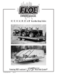
1
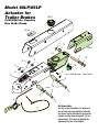
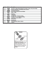
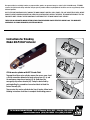
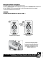
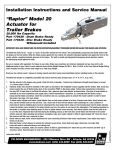
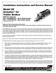
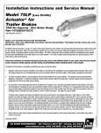
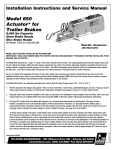
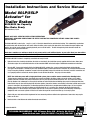
Installation Instructions and Service Manual Model 80LP/85LP Actuator* for Trailer Brakes 8000/8500 lbs Capacity Disc Brake Ready *US Patent No. 6,375,211 MODEL 80LP/85LP ACTUATOR INSTALLATION INSTRUCTIONS IMPORTANT: READ AND UNDERSTAND THE ENTIRE INSTRUCTION PROCEDURE BEFORE USING YOUR BRAKES AND ACTUATOR. The Model 80LP/85LP works by the “surge” or “push” of the trailer toward the tow vehicle when braking. This automatically synchronizes the trailer brakes with the tow vehicle axle brakes. When the trailer pushes against the tow vehicle, the actuator telescopes together and applies force to the master cylinder, supplying hydraulic pressure to the brakes. The built in dampening shock absorber retards the telescoping shock against the hitch ball. Brake laws sometimes are minimum standards and you may wish to add additional brakes to your trailer. Read your tow vehicles owner’s manual on towing capacity and other towing recommendations before installing brakes or this actuator. The Model 80LP/85LP Actuator is completely assembled and ready to install. 1. Hydraulic brake lines should be installed on the trailer as described in the installation manual supplied with the brakes. Note: Some disc brakes require the use of flexible brake lines at the connection POINT on the brake caliper. Follow brake manufacturer instructions. 2. Use only DOT 3 heavy-duty hydraulic fluid in the Model 80LP/85LP actuator. Use a pressure type brake bleeder to bleed brakes. (This type of brake bleeder is available at your local automotive jobber.) Follow manufacturer’s directions. Or, manually bleed the brakes using a heavy-duty flat blade screwdriver inserted in the hole provided on top of the actuator near the front. Insert the screwdriver and use a pumping action to activate the master cylinder in order to bleed the brakes. See page 8 for more details. NOTE: Your trailer may come with a single point bleed system, please read the owners manual before bleeding brakes To bleed master cylinder and brakes, the bleeder hose must be attached to the highest (top) valve on the caliper, on first wheel cylinder to be bled; if tandem axle trailer, bleed closest axle first, and the closest brake on that axle first. Use a loose end of hose from the bleeder valve submerged in a clear plastic container of brake fluid to observe bubbling (hose must be submerged into clean brake fluid to keep air from traveling back into the brake cylinder). Loosen the bleeder screw located in the wheel cylinder one turn, the system is now open to the atmosphere. The bleeding operation for that brake is complete when bubbling stops. Be sure to tighten bleeder screw securely. Each wheel cylinder must be bleed until all air is out of the lines. Replenish the brake fluid during the bleeding process so the level does not fall below half full level in the master cylinder reservoir. When bleeding and testing is completed, make sure master cylinder is filled to 3/8” below the top of the reservoir and filler cap is securely in place. 3. Check with your state motor vehicle department for laws concerning minimum trailer brake requirements. Some states may require brakes on all axles. Instruction #08172 TIE DOWN ENGINEERING • 255 Villanova Drive SW • Atlanta, GA 30336 www.tiedown.com (404) 344-0000 Fax (404) 349-0401 C1032/Rev. 5/22/15 4. Road test trailer a short distance to activate the actuator several times. RATED CAPACITY: Maximum Actuator Capacity: 80LP-8000 lbs. Gross Load, 800 lbs. Maximum Tongue Load 85LP-8000 lbs. Gross Load, 850 lbs. Maximum Tongue Load The actual in-service rating is limited to that of the ball and hitch being used or the trailer manufacturer’s GVWR shown on the certification label, whichever is lower (Note: GVWR is the Gross Vehicle Weight Rating which includes the trailer and the load weight as a Total Gross Weight). HITCHING TRAILER 1. The vehicle, towing hitch and ball must have a rating equal to or greater than trailer GVWR. 2. Model 80LP/85LP will accept 2” trailer hitch balls rated for 8,000# or more only. Trailer balls larger than 2.00” or out of round will not fit the coupler or may result in coupler failure. Balls smaller than 1.970” can cause shock loading and sudden disconnection. Make certain ball latch is in correct position to retain the hitch ball. Push latch back until safety latch engages plate below latch. Insert safety pin into forward hole as a safety lock for the hitch ball coupler prior to towing. Do not tow trailer if coupler is damaged. 3. Connect safety cables or chains using crossed pattern under tongue, or follow trailer manufacturer’s directions. NOTE: The E-stop cable must have slack to make turns right and left without activating the brakes. 4. Connect actuator breakaway cable S-hook to the tow vehicle only. Do not connect S-hook to the safety cables or chains. 5. The breakaway system is designed to only operate after the trailer detaches from the tow vehicle and the safety chains have failed. The breakaway is not a parking brake. Do not use as such. 6. If the E-stop is accidentally applied while un-hitching, see the last page (8) for E-stop release instructions. 7. Any control devices that restrict operation of the actuator cannot be used. This includes certain sway control devices. The actuator must be free to telescope in response to braking action of the tow vehicle. 8. Equalizing or weight distributing hitches may be used, allow six to eight inches free chain length. DANGER: Tongue weight beyond rating limits will interfere with performance of actuator, braking system and the tow vehicle. 9. The actuator is designed for use with Free-Backing trailer brakes. To block braking action, (in order to back up) with other types of brakes, use an electric solenoid. For trailer movement when brakes are not required, place the safety pin in the upper hole on the side of the actuator to block movement of the actuator. DANGER: Failure to remove pin will also prevent forward braking. Pin must be in the lower, forward hole as a safety lock for the hitch ball coupler latch when towing at all times. DIRECTIONS - VEHICLE WIRING - with Free Backing Brake Solenoid 1. Disconnect trailer hitch and any wiring connectors from the vehicle. 2. Connect a 14 gauge wire to the backup (reverse) light wire of the vehicle. This wire should be of sufficient length to attach to the existing vehicle/trailer wire receptacle. The end of this wire will require a female end that will match the solenoid male connector wire. 3. For ease of use, tape or band the end of the reverse light wire to the vehicle’s trailer electrical connector. MAINTENANCE 1. Always check the brake fluid reservoir before using trailer. Make sure it is at least half full. If not, re-fill to 3/8 inch below the top of the reservoir with DOT 3 brake fluid. Check for leaks and repair as required. Never reuse brake fluid. 2. To extend coupler and ball life, coat both with a thin coating of grease. This will also eliminate squeaking. Wipe clean and renew film each time trailer is used. 3. Examine the actuator for bent parts or wear each time the trailer is used. Replace parts as necessary. 4. There are no user adjustments on the actuator. 5. Actuator travel (shown by coupler roller path) over one inch indicates a need to adjust the brakes or add fluid to the reservoir or a need to bleed the brakes and check connections for leaks. Adjust per instructions found in brake installation manual. In general, back-off adjusters on drum brakes from locked position, as required. Adjust Free-Backing brakes by rotating in forward direction only. Failure to adjust may result in loss of braking. Disc brakes do not require adjustment, check for pad wear. 6. While towing, if the actuator appears to be knocking against the hitch ball while starting or stopping, check brake fluid reservoir and fill if below 3/8” full from the top. Low level could indicate a leak in the brake system. WARNING Actuator and brakes should always be flushed with fresh water after using trailer in corrosive conditions. This includes salt water, fertilizers and other corrosive materials. Before storing trailer remove brakes and clean thoroughly. It is also wise to repack the bearings at the same time. Failure to properly and adequately maintain the actuator could cause serious damage, injury or death. WARNING The breakaway system is not designed to operate if the trailer does not separate completely from the tow vehicle, or if the tongue goes under the rear of the tow vehicle. WARNING In the event that the breakaway system is used, check all system components (cable, S-hooks, etc.) for proper working order. Replace any damaged parts with genuine Tie Down parts only. WARNING When resetting the breakaway system, keep hands and fingers clear as you reset the mechanism. Hydraulic pressure held in the system may cause the assembly to snap back suddenly. WARNING AVOID sharp turns, which can cause the actuator to bind or jackknife against the tow vehicle or cause a bend in the tongue. Either can damage the actuator causing brake failure. AVOID towing trailer across large bumps or dips that may over stress the connection between the trailer and tow vehicle, as this could result in damage to the actuator. WARNING DO NOT REUSE BRAKE FLUID. Always use fresh DOT 3 fluid from a fresh container. Failure to maintain proper levels of fluid in the reservoir will cause brake failure. WARNING Failure to install the hitch pin before towing can result in accidental opening of the coupler hitch latch, which can lead to the trailer coming off of the hitch ball, causing serious damage, injury or death. If pin will not fit into the front lower hole, the coupler is not attached properly. Re-set coupler on hitch ball. WARNING A minimum of 5% tongue weight and a maximum 10% tongue weight of the trailer GVWR must be located on the hitch ball. The Trailer tongue should be parallel to the ground. Too much weight can cause premature brake actuation and loss of control of the towing vehicle. To little tongue weight can cause the trailer to fishtail, resulting in loss of control of the tow vehicle and trailer (total trailer weight GVWR includes weight of the trailer plus load). WARNING A loose fit between the coupler and hitch ball can cause the actuator and hitch ball to separate, causing serious damage, injury or death. Check coupler every time prior to towing and at each stop on long trips. Always make certain that coupler latch safety pin is securely installed into coupler latch. WARNING Brake laws sometimes are minimum standards and you may wish to add additional brakes to your trailer. Read your tow vehicles owner’s manual on towing capacity and other towing recommendations before installing brakes or this actuator. WARNING NEVER ALLOW THE COUPLER LATCH SAFETY PIN TO REMAIN IN THE REVERSE LOCKOUT POSITION HOLE. AFTER REVERSE MANEUVERING, ALWAYS INSERT COUPLER LATCH SAFETY PIN BACK INTO COUPLER LATCH. FAILURE TO REMOVE SAFETY PIN FROM REVERSE LOCKOUT POSITION HOLE WILL PREVENT FORWARD MOVEMENT BREAKING WHICH CAN RESULT IN SERIOUS PROPERTY DAMAGE, INJURY OR DEATH. Model 80LP/85LP Actuator for Trailer Brakes 1A & 2 8,000/8500 lbs. Capacity Disc Brake Ready 1A & 3 8 10 1A & 4 1A 9 8 8 7 1B 1A 1C 9 12 10 Set Screw - See Note 9 1A 6 1A 9 5 6 11 Set Screw Note: The Set screw provided in the bottom of the actuator housing should be adjusted to contact the flat provided on the master cylinder casting then backed off 1/4 turn and locked in that adjusted position by tightening the jam nut provided. Part # 17044K 11286 10880K 48986A 48984 48988 50313 11135 48989-3 10544 48753B 48989-4 50301 48971 Description Disc Brake - Master Cylinder Repair Kit, Includes: all nuts, cuffs, pins and clips Disc Brake Solenoid - used with disc brake actuators Set Screw with lock nut Master Cylinder Cap with internal bladder Cover - E-Stop Slide Cuff E-Stop Cable Pin Bullet .56 x 4.3” with zerc fitting Pin Bullet .62” x 4.3” without zerc fitting Jam Nut for 11135 & 48989-3 Bushing Short Bushing Long Safety Cable with stainless steel pin Latch Kit Caution! Jam Nut Bushing NOTE: The jam nut has a lower profile, and is thinner than a standard nut. Caution! Do not use pneumatics with medium or high torque ratings! Use only low torque pneumatics, (1/4" drive butterfly or ratchet wrench recommended) Torque jam nylock nut to 15-20 ft/lbs MAXIMUM. 080714,B1032 Item # 1A 1B 1C 2 3 4 5 6 7 8 9 10 11 12 TIE DOWN ENGINEERING LIMITED WARRANTY Limited Warranty TIE DOWN ENGINEERING Inc (“TIE DOWN”) warrants its products to be free from defects in material and workmanship for one year from date of delivery to the original purchaser when properly installed, used and maintained by the purchaser. This warranty does not apply to damage or loss caused by any or all of the following circumstances or conditions: • Damage caused during installation. •Parts, accessories, materials or components used with or replacing any TIE DOWN braking system not obtained from or approved in writing by TIE DOWN. • Misapplication, misuse and failure to follow the directions or observe cautions and warnings on installation, operation, application, inspection or maintenance specified in any TIE DOWN quotation, acknowledgement, sales literature, specification sheet or installation instruction and service manual (“applicable literature”). • Use of product in any other application other than those described in TIE DOWN’s product information materials. If any TIE DOWN products are found upon TIE DOWN’s examination to have been defective when supplied, TIE DOWN will either: credit the purchaser’s account for the purchase price of the TIE DOWN product; replace the TIE DOWN product; or repair the product. TIE DOWN has sole discretion in choosing which option to provide. For this LIMITED WARRANTY to apply, TIE DOWN must receive notice of the alleged defect within 30 days of either the discovery of the alleged defect or the expiration of the warranty period, whichever is earlier. Any claim not made within this period shall conclusively be deemed waived. If requested by TIE DOWN, purchaser shall return the alleged defective product to TIE DOWN for examination at purchasers expense. TIE DOWN will not pay for expenses incurred in returning a product to TIE DOWN without TIE DOWN’s prior written authority. TIE DOWN shall not be liable for any other expenses purchaser incurs to remedy any defect. Purchasers waive subjugation on all claims under any insurance. Limitation of Liability: It is expressly agreed that the liability of TIE DOWN is limited and TIE DOWN does not function as an insurer. THE REMEDIES SET FORTH IN THIS WARRANTY SHALL CONSTITUTE THE EXCLUSIVE REMEDIES AVAILABLE TO THE PURCHASER OR USER AND ARE IN LIEU OF ALL OTHER REMEDIES, EXPRESS OR IMPLIED. THE LIABILITY OF TIE DOWN, WHETHER IN CONTRACT, IN TORT, UNDER ANY WARRANTY OR OTHERWISE, SHALL NOT EXCEED THE PURCHASE PRICE OF THE PARTICULAR PRODUCT MANUFACTURED, SOLD OR SUPPLIED BY TIE DOWN. To Obtain Technical Assistance: To enable TIE DOWN to respond to a request for assistance or evaluation of customer or user operating difficulty, please provide at a minimum the following information by calling 1-800-241-1806: • Model number, serial number and all other data on the specific component which appears to be involved in the difficulty. • The date and from whom you purchased your TIE DOWN product. • State your difficulty, being sure to mention at least the following: Application, Nature of load involved, and Weight of the load. Field Service If field service at the request of the purchaser is rendered and the difficulty is found not to be with TIE DOWN’s product, the purchaser shall pay the time and expense (at the prevailing rate at the time of service) of seller’s field representative(s). Charges for service, labor and other expenses that have been incurred by the purchaser, its customer or agent without prior written authorization of TIE DOWN will not be accepted. TIE DOWN ENGINEERING • 255 Villanova Drive SW • Atlanta, GA 30336 TIE DOWN EXTENDS NO WARRANTY, EXPRESS OR IMPLIED, ON PRODUCTS NOT MANUFACTURED BY TIE DOWN OR TO www.tiedown.com (404) 344-0000 Fax (404) 349-0401 TIE DOWN’S DESIGN SPECIFICATION, INCLUDING BUT NOT LIMITED TO SUCH ITEMS AS NON-TIE DOWN TIRES, BRAKES, ACTUATORS, BEARINGS, HOSE AND TUBING. PURCHASER’S RECOURSE SHALL BE LIMITED TO ANY WARRANTY OF THE RESPECTIVE MANUFACTURERS. THIS WARRANTY EXCLUDES ALL IMPLIED WARRANTIES OF MERCHANTABILITY OR FITNESS FOR A PARTICULAR PURPOSE OR ANY PURPOSE. 4 color THIS WARRANTY DOES NOT COVER NOR EXTEND TO INCIDENTAL OR CONSEQUENTIAL DAMAGE. Some states do not allow the exclusion or limitation of incidental or consequential damages, so the above limitation or exclusion may not apply to you. This warranty gives you specific legal rights, and you may also have other rights which vary from state to state. TIE DOWN ENGINEERING • 255 Villanova Drive SW • Atlanta, GA 30336 www.tiedown.com (404) 344-0000 Fax (404) 349-0401 No representative has authority to make any representation, promise or agreement except as stated in this Limited Warranty. TIE DOWN reserves the right to make design and other changes upon its products without any obligation to install the same on any previously sold or delivered products. DUE TO THE WIDE VARIATION IN USES TO WHICH TIE DOWN PRODUCTS (WHEELS, HUBS, BRAKES, ETC.) ARE SUBJECTED BY USERS, WE ARE UNABLE TO SPECIFY CARRYING CAPACITIES OR SPEEDS FOR A PARTICULAR APPLICATION. THEREFORE, THE MANUFACTURER MUST TEST HIS EQUIPMENT UNDER THE MOST SEVERE CONDITIONS TO DETERMINE THAT TIE DOWN PRODUCTS ARE SUITABLE. THERE ARE NO WARRANTIES WHICH EXTEND BEYOND THOSE DESCRIBED ABOVE. EFFECTIVE JANUARY 2001 THIS WARRANTY SUPERSEDES ALL PRIOR WARRANTIES, WRITTEN OR IMPLIED. Instructions for Bleeding Model 80LP/85LP Actuator a b 1 Fill the master cylinder with DOT 3 brake Fluid. To pump bleed the master cylinder, remove the access cover. Insert 2 a flat tip screwdriver between the brake release lever (#1-a) and the emergency stop release bracket (#1-b). Hold down the emergency stop release bracket (#2). Pump the Villanova brake fluid byDrive SW • Atlanta, GA 30336 TIE DOWN ENGINEERING • 255 pushing/pulling the screwdriver forward and back to(404) bleed the www.tiedown.com 344-0000 Fax (404) 349-0401 brakes manually (#3). 3 TIE DOWN ENGINEERING • 255 Villanova Drive SW • Atlanta, GA 30336 www.tiedown.com (404) 344-0000 Fax (404) 349-0401 TDE MO D L SAE P8000 EL C MA LASS XG IV 800 VW 0L BS To pressurize the master cylinder brake lines & brakes; follow brake bleeding instructions for brakes to complete the bleeding process. 4 color Emergency Brake Is Engaged: Illustrations #1 & #2 show the top of the actuator/access cover. #1 Shown in “NORMAL POSITION”. Be sure that there are no signs of the red “EMERGENCY STOP” bracket in view. #2 If the “EMERGENCY STOP” release bracket (Red) is visible, the emergency brake has been engaged. To release the Emergency Stop, see illustration #3. WARNING: DO NOT TOW THE VEHICLE IF YOU SEE “RED” ! 1 TDE48984 2 EMERGENCY STOP Emergency Stop Bracket (in Red) ENGAGED NORMAL POSITION FRONT TDE48984 EMERGENCY STOP ENGAGED NORMAL POSITION FRONT - Normal Use Emergency Stop Disengaged Emergency Stop Engaged • DO NOT TOW • TDE MO D L SAE P8000 EL C MA LASS XG IV 800 VW 0L BS FR ON T 3 To Release the Emergency Brake: Press down the emergency stop release bracket with a screwdriver (#3-a) until the E-stop bracket snaps back into the “NORMAL POSITION” (#1). TIE DOWN ENGINEERING • 255 Villanova Drive SW • Atlanta, GA 30336 www.tiedown.com (404) 344-0000 Fax (404) 349-0401 C1032/Rev. 5/20/15 98 E4 8 TD EM E RG E ST NCY EN OP GA GE D NO PO RMA SIT L ION 4 a