1
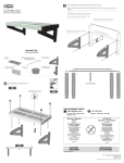
E2512, E2522
and E2532 GRILLS
INSTALLATION and
SERVICING INSTRUCTIONS
IMPORTANT
The installer must ensure that the installation of the appliance is in conformity with these instructions and
National Regulations in force at the time of installation. Particular attention MUST be paid to -
BS7671 IEE Wiring Regulations
Electricity at Work Regulations
Health And Safety At Work Act
Fire Precautions Act
This appliance has been CE-marked on the basis of compliance with the Low Voltage and EMC Directives for
the voltages stated on the Data Plate
WARNING -THIS APPLIANCE MUST BE EARTHED
On completion of the installation these instructions should be left with the Engineer-in-Charge for reference
during servicing. Further to this, The Users Instructions should be handed over to the User, having had a
demonstration of the operation and cleaning of the appliance.
IT IS MOST IMPORTANT THAT THESE INSTRUCTIONS BE CONSULTED BEFORE INSTALLING AND
COMMISSIONING THIS APPLIANCE. FAILURE TO COMPLY WITH THE SPECIFIED PROCEDURES MAY
RESULT IN DAMAGE OR THE NEED FOR A SERVICE CALL.
PREVENTATIVE MAINTENANCE CONTRACT
In order to obtain maximum performance from this unit we would recommend that a Maintenance Contract be
arranged with SERVICELINE. Visits may then be made at agreed intervals to carry out adjustments and
repairs. A quotation will be given upon request to the contact numbers below.
WEEE Directive Registration No. WEE/DC0059TT/PRO
At end of unit life, dispose of appliance and any replacement parts
in a safe manner, via a licenced waste handler.
Units are designed to be dismantled easily and recycling of all
material is encouraged whenever practicable.
Falcon Foodservice Equipment
HEAD OFFICE AND WORKS
Wallace View, Hillfoots Road, Stirling. FK9 5PY. Scotland.
SERVICE CONTACT -
PHONE - 01438 363 000
FAX - 01438 369 900
T100483 Ref. 2
Warranty Policy Shortlist
Warranty does not cover :Correcting faults caused by incorrect installation of a product.
Where an engineer cannot gain access to a site or a product.
Repeat commission visits.
Replacement of any parts where damage has been caused by misuse.
Engineer waiting time will be chargeable.
Routine maintenance and cleaning.
Gas conversions i.e. Natural to Propane gas.
Descaling of water products and cleaning of water sensors where softeners/conditioners are not fitted, or are
fitted and not maintained.
Blocked drains.
Independent steam generation systems.
Gas, water and electrical supply external to unit.
Light bulbs.
Re-installing vacuum in kettle jackets.
Replacement of grill burner ceramics when damage has been clearly caused by misuse.
Where an engineer finds no fault with a product that has been reported faulty.
Re-setting or adjustment of thermostats when unit is operating to specification.
Cleaning and unblocking of fryer filter systems due to customer misuse.
Lubrication and adjustment of door catches.
Cleaning and Maintenance
Cleaning of burner jets
Poor combustion caused by lack of cleaning
Lubrication of moving parts
Lubrication of gas cocks
Cleaning/adjustment of pilots
Correction of gas pressure to appliance.
Renewing of electric cable ends.
Replacement of fuses
Corrosion caused by use of chemical cleaners.
SECTION 1 - INSTALLATION
UNLESS OTHERWISE STATED, PARTS WHICH HAVE BEEN PROTECTED BY THE MANUFACTURER
ARE NOT TO BE ADJUSTED BY THE INSTALLER
Mains connection must be made via a suitably rated
1.1 MODEL NUMBER, NETT WEIGHTS
isolating switch with a contact separation of at least
and DIMENSIONS
3mm on all poles. The use of heat resistant cable is
WIDTH
DEPTH
HEIGHT
WEIGHT
WEIGHT
recommended. Wiring should be in accordance with
MODEL
mm
mm
mm
kg
lbs
current IEE Wiring Regulations.
E2512
700 560 510
48
106 Particular attention must be paid to providing
adequate and effective earthing using the earth
E2522
900 560 510
77
170 terminal provided. When connecting the E2522 model
to a single phase supply, link terminals L1 and L2 to
E2532
785 330 325
31
68
form the 'line' terminal.
1.2 SITING
Installation should be made in accordance with local
and/or national regulations applying at the time and a
competent installer must be employed. There should
be a clearance of 200mm from any wall or object
liable to damage from overheating and 75mm
clearance should be left from any wall to allow
removal of the side panels for maintenance.
In the event of a requirement to position this
appliance in close proximity to a wall, partion, kitchen
furniture or decorative finish, etc. it is recommended
that these be constructed of a non-combustible
material. If this is not possible then these surfaces
require to be clad in a non-combustible, heat
insulating material. Close attention must be paid to
fire prevention regulations.
The grill should be installed level and in a well lit
position with adequate ventilation. Bench mounting
legs are available for installing the grill on a working
surface. When these are used, it is essential that they
be secured to the surface, using fixings provided.
1.4 ELECTRICAL LOADINGS
The electrical loading is stated on unit data plate.
SECTION 2 - ASSEMBLY
2.1 GRILL MOUNTING INSTRUCTIONS
2.1.1 Wall Mounting
The installer must ensure that the wall on which the
grill is to be mounted is suitable to carry the weight
and can be suitably plugged to take No.8 x 50mm
wood screws (minimum length). Hold shelf against
wall as a template at required height. While keeping
top surface horizontal, mark fixing positions. Remove
shelf and drill wall to receive suitable plugs for No.8
screws. Secure helf in position and place grill on
shelf. Secure grill using fixings provided via holes
4 and 6 and the corresponding holes in grill base.
Mounting
The grill can be mounted upon:
A specially designed eye level floorstand.
Legs: 230mm or 336mm high.
A wall bracket.
1
2
3 5
6
Note
The appliance must NOT be mounted directly on to a
combustible surface.
1.3 WIRING THE APPLIANCE
Warning
THIS APPLIANCE MUST BE EARTHED
A cable entry suitable for 20mm conduit is situated in
the unit rear at the RH side. To gain access to the
terminals, the top facia and the vertical switch panel
must be removed. The facia is secured on the
underside and the vertical switch panel secured by
one fixing at the bottom.
Additional access can be obtained if required by
removing top panel, according to procedure
described under heading 'Maintenance of Elements'.
5
3
1
1
2 3
4
1
4 3
2
2
4
6
3.2 ELEMENTS
3.2.1 E2512/2522 Models
1 or 3
3 or 1
2
Table Mounting
Lay grill on its back carefully. Remove Fixing 1 from
unit base. Insert fixings through holes 1, 2 and 3 of leg
plate to corresponding holes in grill base. Stand
appliance upright on legs.
4
5
These units are fitted with a number of identical
elements which may be replaced individually.
To replace a faulty element, proceed as follows:
Undo fixings on control panel underside. Ease panel
out at the bottom and lift it up, away from the top
retaining screws.
Undo back panel fixings and remove panel.
Remove fixings from both sides of element control
bracket, gaining access from the front of the unit.
Undo fixings which secure element to rear inner panel
and withdraw element.
Fit replacement element and replace additional parts
in reverse order.
3.2.2 E2532 Model
This model is fitted with a single element. To replace
a faulty element, proceed as follows:
Undo fixings on top front facia and remove.
Undo fixings on control panel top and underside and
remove. Remove fixings at top panel rear and front.
Support rear panel until top is removed. Undo fixing at
bottom of rear panel and remove.
Remove heat shield above elements (secured by 2
toggle brackets, one at either side). Remove element
connections at terminal posts. Undo fixing which
secures element to RH side panel and withdraw
element. Fit replacement element and replace panels
which have been removed to gain access.
3.3 ENERGY REGULATOR
2.1.2 Floor Stand
Assemble stand as detailed on instruction sheet. Lift
grill on to angled cross pieces.
Secure through holes 4 and 5 to corresponding holes
in grill base.
Adjust levelling feet until stand sits firmly and level.
SECTION 3 - SERVICING
Before attempting any maintenance, isolate unit at
main switch. Take steps to ensure that it cannot
inadvertently be switched on.
3.1 MAINS INDICATOR LAMP
An indicator neon is located on the control panel and
must be replaced if failure occurs. Undo bottom fixing
and remove panel. Ease panel down from behind top
facia. Remove 2 lamp connections. Connect
replacement neon and replace control panel.
Remove knob and control panel. Undo screws which
secure regulator to control panel and remove
regulator. Note wire connection locations and transfer
each to corresponding position on the control.
Fit replacement control to panel and re-fit panel.
3.4 RELAY
3.4.1 E2512/E2522 Grills - To Replace
Undo back panel fixings and remove panel.
Undo fixings which secure relay to bracket and
remove relay.
Note wire connections and locations and transfer
each to the corresponding position on the new relay.
Secure mounting bracket and replace panels in
reverse order.
3.4.2 E2532 Grill - To Replace
Remove top, control and outer side panels. Relay can
now be removed from the bracket by undoing fixing
nut. Note connection locations and transfer wires to
replacement relay. Secure to mounting bracket and
replace panels in reverse order.
79414WB
MARGAID GNIRIW 2152E
87314WB
MARGAID GNIRIW 2252E
75414WB
MARGAID GNIRIW 2352E
23614WB - MARGAID GNIRIW EROHSFFO
LARTUEN ON/ESAHP OWT - 2152E
43614WB - MARGAID GNIRIW EROHSFFO
LARTUEN ON/ESAHP EERHT - 2252E
68734WB - MARGAID GNIRIW EROHSFFO
LARTUEN DNA ESAHP OWT - 2252E