1
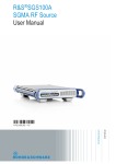
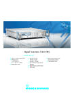
Product Brochure | 02.00 Test & Measurement R&S®SGS100A SGMA RF Source Compact – fast – reliable R&S®SGS100A SGMA RF Source At a glance The R&S®SGS100A is an RF source designed to meet the requirements of automated test systems. It is available as a CW source or as a vector signal generator with an integrated I/Q modulator. With its frequency range of up to 12.75 GHz, the vector signal generation version covers the essential digital signals. The CW version can be used as a flexible local oscillator as well as for interference testing against mobile radio standards. The very compact dimensions of only one height unit and ½ 19" rack width and the extremely fast frequency and level setting times are two features that demonstrate how consistently the R&S®SGS100A has been designed for use in systems. It can also be used in all applications that require either multiple RF signal sources, such as beamforming applications, or where an extremely compact RF generator is needed, e.g. an operating source in customer systems. 2 Though compact, the R&S®SGS100A provides uncompromising signal purity and level accuracy. It offers performance usually available only from high-end instruments, including high output power, level repeatability and modulation bandwidth. During development, particular emphasis was placed on the total cost of ownership. A long calibration interval, excellent serviceability and options for expansion maximize the availability of the RF source. Since the RF source is typically remote-controlled, the front panel of the R&S®SGS100A has a minimalist design. However, it offers status LEDs as well as all of the keys necessary for controlling generator operation. When used as a benchtop instrument, the R&S®SGS100A is operated manually using the R&S®SGMA-GUI software included with the instrument. Key facts ❙❙ Smallest fully integrated vector signal generator on the market, space-saving design for system integration ❙❙ Enables high throughput due to very short frequency and level setting times of typ. 280 µs via PCIe interface ❙❙ Excellent RF performance in a compact format ❙❙ Maximum output level of typ. +22 dBm for compensating losses in the setup ❙❙ Closed ALC loop for CW and I/Q modes for highest level repeatability ❙❙ High output frequency of up to 12.75 GHz for broad applicability ❙❙ Wear-free electronic attenuator for high reliability ❙❙ Very cost-efficient with low initial costs and low cost of ownership R&S®SGS100A SGMA RF Source Benefits and key features Dedicated ATE signal source ❙❙ Smallest integrated signal generator: 1 HU, ½ 19" for minimized required space in the test system ❙❙ Very fast setting times via PCIe interface for high throughput ❙❙ Maximum level of typ. +22 dBm (with R&S®SGS-B26 electronic step attenuator option) for compensating losses in the setup ❙❙ Optional wear-free electronic attenuator up to 12.75 GHz for reliable operation ▷▷ page 4 High performance in the right package ❙❙ Very high level linearity and repeatability for c onstant test conditions ❙❙ Low SSB phase noise of typ. –130 dBc (20 kHz carrier offset, f = 1 GHz, 1 Hz measurement bandwidth) ❙❙ Optional high-stability reference oscillator for easy integration of a standard in the test system ▷▷ page 6 Minimized total cost of ownership ❙❙ Attractive initial cost ❙❙ Straightforward modular design for short repair times, minimizing test system downtime ❙❙ Long calibration interval for minimized service costs ▷▷ page 8 R&S®SGS100A model overview CW source as local oscillator Vector signal generator for generating digital signals with an external baseband signal 1 MHz to 6 GHz 1 MHz to 12.75 GHz 80 MHz to 6 GHz 80 MHz to 12.75 GHz with R&S®SGS-B106 with R&S®SGS-B106 and R&S®SGS-B112 with R&S®SGS-B106V with R&S®SGS-B106V and R&S®SGS-B112V Rohde & Schwarz R&S®SGS100A SGMA RF Source 3 Dedicated ATE signal source Histogram of 10 000 frequency setting times measured via PCIe interface, Setting Characteristic: AUTO Maximum available level for a CW signal, Setting Characteristic: AUTO, with R&S®SGS-B26 electronic step attenuator option (measured) 4 Smallest integrated signal generator: 1 HU, ½ 19" for minimized required space in the test system A look at the R&S®SGS100A confirms that it has been designed specifically for use in an automated environment. The small size of only one height unit and ½ 19" rack width saves space in the test system, and also reduces costs. Four RF paths can now be placed in the space previously needed for one RF path on average – a clear space management advantage. This makes the R&S®SGS100A ideal for ATE applications, even where multiple RF sources are required simultaneously, such as when testing phased array antenna systems. Low power consumption and the corresponding low heat dissipation make it possible to place the RF generators close to one another. The connectors are arranged as standard on the back of the instrument to allow simple integration. Status LEDs on the front panel clearly indicate the instrument operating status. Very fast setting times via PCIe interface for high throughput Production applications require speed during testing to ensure high throughput. The R&S®SGS100A meets this requirements in several ways. Its internal architecture and the software are designed for top speed. In addition, the PCIe interface transmits the remote control commands at maximum speed. Special commands (based on a Rohde & Schwarz driver) can be used to control the generator directly. This eliminates the need for a time-consuming translation of high-level commands in the instrument, again increasing the speed. With these optimizations, the R&S®SGS100A is able to achieve frequency and level setting times of typ. 280 µs. This was previously possible only by using vector signal generators with List modes, but not when issuing individual remote control commands directly. The test sequence can be adapted flexibly in the software without having to renew the frequency lists and the level lists. Maximum level of typ. +22 dBm (with R&S®SGS-B26 electronic step attenuator option) for c ompensating losses in the setup In a complex test system, typical level losses of several dB occur between the signal generator and the DUT. These result from the cable loss of long cables and from the use of switching matrices and filters. With its output level of typ. +22 dBm, the R&S®SGS100A provides sufficient margin to compensate for such losses. This eliminates the need for additional amplifiers that would not only increase the cost and take up more space, but also negatively affect signal purity, including wideband noise, level stability and impedance matching. Optional wear-free electronic attenuator up to 12.75 GHz for reliable operation The R&S®SGS100A in a test system. The attenuator (R&S®SGS-B26 option) up to 12.75 GHz is fully electronic and wear-free. This allows continuous, long-term use in a test system, even when there is very frequent level switching, and, as a result, also minimizes service costs. Rohde & Schwarz R&S®SGS100A SGMA RF Source 5 High performance in the right package Very high level linearity and repeatability for constant test conditions The R&S®SGS100A, designed for speed and compactness, offers performance previously available only from high-end benchtop instruments. One example is the maximum output power of typ. +22 dBm with an electronic attenuator that can be used to compensate for losses in the system. But maximum level isn't everything. Especially in a calibrated test system level repeatability and linearity are essential for a generator. High level repeatability ensures consistent test conditions and makes it possible to reduce tolerances when defining test limits. With narrower test limits, production yield increases. Level linearity is particularly important when testing amplifier chips to exactly determine their compression point across level. This requires precise mapping of even very small level steps. Level repeatability for a 3GPP TM1/64 signal with a crest factor of 10.55 dB, at 5 dBm (measured) Low SSB phase noise of typ. –130 dBc (20 kHz carrier offset, f = 1 GHz, 1 Hz measurement bandwidth) An important characteristic for the signal quality of RF signal generators is SSB phase noise. This value is important for CW applications, for example when searching for a pure local oscillator, and also for digital modulations. SSB phase noise directly influences the error vector magnitude (EVM) of digital signals, a parameter that is significant for advanced OFDM-based systems such as LTE. For interference and intermodulation tests, very low nonharmonics are an indispensable characteristic for the test source. The R&S®SGS100A is ahead of the game here as well, offering excellent values otherwise seen only with high-end instruments: At an output frequency lower than < 1.5 GHz, the R&S®SGS100A achieves < –76 dBc (offset > 10 kHz). Level linearity for a 3GPP TM1/64 signal with a crest factor of 10.55 dB; the different colors are for different RF frequencies (measured) 6 Optional high-stability reference oscillator for easy integration of a standard in the test system All of the test instruments in a system are typically linked via a 10 MHz reference so that their frequencies can be synchronized. The R&S®SGS100A can be used for this purpose when equipped with an optional, highly stable 10 MHz reference source. In addition, the R&S®SGS100A uses external reference signals of 100 MHz and 1 GHz for synchronization. The higher frequency ensures a more stable instrument interconnection, not only with respect to frequency but also with respect to phase stability. When running tests (for example, beamforming applications) that require absolutely phase-locked connections between multiple signal sources, the R&S®SGS100A can also be equipped with the R&S®SGS-K90 option that offers a coherent LO input and output. With its very high I/Q modulation bandwidth, the R&S®SGS100A is not only flexible, it is also a secure investment. It is capable of generating signals with an RF bandwidth of 1 GHz above a 2.5 GHz carrier frequency. This covers all modern wideband communications standards. This bandwidth not only allows predistortion, it also makes it possible to obtain an exact description of digitally generated pulses with steep pulse edges for aerospace and defense applications. Frequency response of the I/Q modulator (measured) SSB phase noise with R&S®SGS-B1 internal OCXO option (measured) –30 10 MHz 100 MHz 1 GHz 3 GHz 6 GHz 10 GHz SSB phase noise in dBc (1 Hz) –40 –50 –60 –70 –80 –90 –100 –110 10 GHz –120 6 GHz 3 GHz –130 1 GHz –140 100 MHz –150 –160 1 10 MHz 10 100 1 000 10 000 100 000 1 million 10 million Frequency offset in Hz Rohde & Schwarz R&S®SGS100A SGMA RF Source 7 Minimized total cost of ownership Attractive initial cost The total cost of ownership includes not only attractive initial costs, but also the service and calibration costs. The R&S®SGS100A is designed for optimal stability and minimal service effort. This is an important factor in ensuring maximum availability in the system. The low power consumption of 70 W has several benefits: The instrument temperature is decreased, which reduces component wear and tear and minimizes heat dissipation that would require venting throughout the system. The low power consumption translates into low operating costs. Straightforward modular design for short repair times, minimizing test system downtime If a repair is needed, the internal selftest identifies the affected component and minimizes troubleshooting time and effort. The low number of modules makes service even faster and easier. Long calibration interval for minimized service costs Another factor is the long-term stability of the g enerator: The longer the instrument operates without drift, the longer the calibration interval that can be selected. This is important because each time an instrument is calibrated, it must be removed from the test setup and sent to a calibration lab. The recommended calibration interval is three years, ensuring long availability. Inside view. 8 Connectivity All of the connectors are arranged as standard on the back of the instrument to allow simple integration into a test system. SMA ports provide functional connections, including RF output and analog I/Q inputs. The typically small cable diameters of this space-saving design facilitate cabling throughout the system. Though small in size, the R&S®SGS100A provides m ultiple remote control options. PCIe is recommended for maximum setting speed together with a corresponding instrument driver from Rohde & Schwarz, which is a vailable for Windows and Linux. The two additional remote control interfaces, i.e. LAN (Gigabit Ethernet) and USB 2.0, offer high speed to ensure short test times and high throughput. The R&S®SGMA-GUI PC software, which comes standard with the instrument, is used for manual operation. It can control up to twelve R&S®SGS100A simultaneously, and also provides access to all instrument functions and settings via all interfaces. The R&S®SGS100A with the R&S®SGMA-GUI PC software for controlling up to twelve instruments. Ports on the rear panel. Rohde & Schwarz R&S®SGS100A SGMA RF Source 9 Specifications in brief Specifications in brief Frequency Frequency range Setting time with the R&S®SGS-B106 option 1 MHz to 6 GHz with the R&S®SGS-B106 and R&S®SGS-B112 options with the R&S®SGS-B106V option 1 MHz to 12.75 GHz with the R&S®SGS-B106V and R&S®SGS-B112V options with PCIe remote control Input frequency for external reference 80 MHz to 6 GHz (I/Q mode) 1 MHz to 6 GHz (CW mode) 80 MHz to 12.75 GHz (I/Q mode) 1 MHz to 12.75 GHz (CW mode) < 500 μs 10 MHz, 100 MHz, 1000 MHz Level Specified level range –10 dBm to +15 dBm (PEP) 1) with the R&S®SGS-B26 option Level error Setting Characteristic: AUTO; temperature range from +18 °C to +33 °C 1 MHz ≤ f ≤ 3 GHz 3 GHz < f ≤ 12.75 GHz Output impedance VSWR in 50 Ω system Setting time –120 dBm to +15 dBm (PEP) 1) in full frequency range, Setting Characteristic: AUTO in full frequency range, with the R&S®SGS-B26 option with PCIe remote control, Setting Characteristic: AUTO < 0.5 dB < 0.9 dB < 2.0 < 1.8 < 500 μs Spectral purity Harmonics level ≤ 8 dBm, CW, I/Q wideband OFF < –30 dBc Nonharmonics level > –10 dBm 2), offset > 10 kHz from carrier, f ≤ 1.5 GHz level > –10 dBm 2), f ≤ 3 GHz < –76 dBc Subharmonics Wideband noise SSB phase noise < –76 dBc 1 MHz ≤ f ≤ 6 GHz and 10 MHz carrier offset, < –145 dBc 6 GHz < f ≤ 12.75 GHz and 30 MHz carrier offset, AUTO mode, level > 5 dBm, 1 Hz measurement bandwidth, CW 20 kHz carrier offset, 1 Hz measurement bandwidth f = 1 GHz < –126 dBc, typ. –130 dBc f = 10 GHz < –106 dBc, typ. –110 dBc I/Q modulation I/Q modulator bandwidth (RF) 100 MHz < f ≤ 2.5 GHz, I/Q wideband 40 % of carrier frequency 2.5 GHz < f ≤ 12.25 GHz, I/Q wideband 1 GHz Error vector measured with 16QAM, filter root cosine α = 0.5, 10 kHz symbol rate ACLR WCDMA 3GPP FDD, TM 1/64 f > 80 MHz, RMS < (0.4 % + 0.2 % × f/GHz) > 67 dB, 69.5 dB (meas.) Baseband bypass mode Frequency range 1 MHz ≤ f ≤ 80 MHz Specified level range –5 dBm to +15 dBm with the R&S®SGS-B26 option –120 dBm to +15 dBm using Rohde & Schwarz instrument driver PCIe (single lane) using SCPI 1999.5 or compatible command sets Ethernet (TCP/IP) 10/100/1000BaseT using SCPI 1999.5 or compatible command sets USB 2.0 Dimensions W×H×D Weight when fully equipped 250 mm × 52.5 mm × 401 mm (9.84 in × 2.07 in × 15.79 in) 1 HU, ½ 19" rack width 4.0 kg (8.82 lb) Remote control General data Power consumption 1) 70 W (meas.) PEP = peak envelope power. > 0 dBm for instruments without the R&S®SGS-B26 electronic step attenuator. 2) 10 Ordering information Designation Type Order No. SGMA RF Source 1) R&S®SGS100A Including power cable, Quick Start Guide and CD-ROM (with R&S®SGMA-GUI, operating and service manual) Options 1 MHz to 6 GHz, CW (no modulation) R&S®SGS-B106 1 MHz to 6 GHz, I/Q (with vector modulation) R&S®SGS-B106V R&S®SGS-B112 Frequency Extension to 12.75 GHz, CW 2) R&S®SGS-B112V Frequency Extension to 12.75 GHz, I/Q (with vector modulation) 3) Electronic Step Attenuator R&S®SGS-B26 Reference Oscillator OCXO R&S®SGS-B1 Phase Coherent Input/Output R&S®SGS-K90 Recommended extras 19" Rack Adapter (for two 1 HU instruments next to each other), R&S®ZZA-KN20 suitable for installation of two Rohde & Schwarz SGMA instruments 19" Rack Adapter (for one instrument and spacing module) R&S®ZZA-KN21 Accessories Documentation of Calibration Values R&S®DCV-2 1416.0505.02 1416.2308.02 1416.2350.02 1416.1553.02 1416.1576.02 1416.1353.02 1416.2408.02 1416.2608.02 1175.3191.00 1175.3204.00 0240.2193.18 The base unit must be ordered together with an R&S®SGS-B106 or R&S®SGS-B106V frequency option. Requires R&S®SGS-B106. 3) Requires R&S®SGS-B106V. 1) 2) Service options Extended Warranty, one year R&S®WE1SGS100A Extended Warranty, two years R&S®WE2SGS100A Extended Warranty, three years R&S®WE3SGS100A Extended Warranty, four years R&S®WE4SGS100A Extended Warranty with Calibration Coverage, one year R&S®CW1SGS100A Extended Warranty with Calibration Coverage, two years R&S®CW2SGS100A Extended Warranty with Calibration Coverage, three years R&S®CW3SGS100A Extended Warranty with Calibration Coverage, four years R&S®CW4SGS100A Please contact your local Rohde & Schwarz sales office. For data sheet, see PD 5214.5703.22 and www.rohde-schwarz.com Rohde & Schwarz R&S®SGS100A SGMA RF Source 11 Service you can rely on JWorldwide J Local and personalized and flexible J Uncompromising quality J Long-term dependability J Customized About Rohde & Schwarz Rohde & Schwarz is an independent group of companies specializing in electronics. It is a leading supplier of solutions in the fields of test and measurement, broadcasting, radiomonitoring and radiolocation, as well as secure communications. Established more than 75 years ago, Rohde & Schwarz has a global presence and a dedicated service network in over 70 countries. Company headquarters are in Munich, Germany. Environmental commitment ❙❙ Energy-efficient products ❙❙ Continuous improvement in environmental sustainability ❙❙ ISO 14001-certified environmental management system Certified Quality System ISO 9001 Rohde & Schwarz GmbH & Co. KG www.rohde-schwarz.com Regional contact ❙❙ Europe, Africa, Middle East | +49 89 4129 12345 [email protected] ❙❙ North America | 1 888 TEST RSA (1 888 837 87 72) [email protected] ❙❙ Latin America | +1 410 910 79 88 [email protected] ❙❙ Asia/Pacific | +65 65 13 04 88 [email protected] ❙❙ China | +86 800 810 8228/+86 400 650 5896 [email protected] R&S® is a registered trademark of Rohde & Schwarz GmbH & Co. KG Trade names are trademarks of the owners | Printed in Germany (ch) PD 5214.5703.12 | Version 02.00 | July 2012 | R&S®SGS100A Data without tolerance limits is not binding | Subject to change © 2012 Rohde & Schwarz GmbH & Co. KG | 81671 München, Germany 5214570312