1
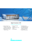
Version 01.00 ¸SMF100A Microwave Signal Generator Signal generation redefined ◆ Excellent signal quality ◆ Very high output power ◆ Ideal in all areas – R & D – Production – Service as well as maintenance and repair ◆ Selection of interfaces ◆ Innovative operating concept January 2007 At a glance Signal quality, speed, and flexibility – these are decisive properties for a signal generator in the microwave range. Special features To meet even the highest of requirements, the ¸SMF100A microwave signal generator was designed and developed as a completely new product. The result is a first-rate, stateof-the-art microwave signal generator that sets new standards. It thus covers the numerous fields of application encountered in R & D, production, service, maintenance, and repair. The ¸SMF100A operates in the frequency range from 1 GHz to 22 GHz. In addition to CW signals, all common types of analog modulation (AM, FM, jM, pulse modulation) or combinations thereof can be generated. For just one example among many, take the following application: What can you do when cable loss at high frequencies starts becoming a larger and larger problem? Subsequent amplifiers represent one solution – or you can simply use the ¸SMF100A equipped with the option that supplies an output power of typ. +26 dBm at 22 GHz. The ¸SMF100A signal generator offers a modern graphical user interface for fast and intuitive operation. The settings – which, for the first time in a microwave signal generator, can be controlled via a block diagram – and the signal flow can be seen at a glance. ¸SMF100A Microwave Signal Generator Excellent signal quality ◆ Exceptionally low single sideband phase noise: typ. –120 dBc (at 10 GHz; 10 kHz carrier offset; 1 Hz measurement bandwidth) ◆ Very low wideband noise: typ. –148 dBc (at 1 GHz ≤ f ≤ 11 GHz; >10 MHz carrier offset; 1 Hz measurement bandwidth; at +10 dBm) ◆ Very low harmonics: typ. –55 dBc (at 1 GHz ≤ f ≤ 22 GHz; at +10 dBm) ◆ High suppression of nonharmonics: typ. –67 dBc (at 1 GHz < f ≤ 11 GHz; >3 kHz carrier offset; at +10 dBm) Ideal for use in production ◆ Very short level and frequency setting times across entire level and frequency range: <4 ms (frequency), <3 ms (level), <700 µs (List mode) ◆ Very high output power of up to typ. +26 dBm ◆ Outstanding absolute level accuracy and level repeatability ◆ Selection of interfaces for remote control ◆ Low space requirement in rack: only three height units Aerospace & defense applications ◆ Optional pulse modulator with excellent data: >80 dB on/off ratio <10 ns rise/fall time <20 ns pulse width ◆ Optional pulse generator ◆ Optional removable compact flash disk to meet high security requirements All-purpose applications ◆ Frequency range 1 GHz to 22 GHz ◆ Frequency, level, and LF sweeps ◆ AM, broadband FM/jM, pulse modulation ◆ Two multifunction generators up to 10 MHz Intuitive operating concept ◆ Intuitive operating interface with graphical representation of the signal flow (block diagram) ◆ Operation with rotary knob on instrument or with USB mouse ◆ VGA color display with 640 × 480 pixels Selection of interfaces ◆ Remote control via GPIB or LAN ◆ USB ports for keyboard, mouse, and memory stick ◆ Connector for ¸NRP power sensors for precise power measurement ◆ Control via remote operation tool (e.g. VNC) Everything in one instrument The ¸SMF100A base unit with frequency option included already offers the essential functions and interfaces. This basic configuration can be adapted to meet the requirements of further applications by adding specific options. The ¸SMF100A has outstanding specifications. Additional options for improving performance are not needed. This gives you a decisive advantage as the user. You no longer need to carry out tedious option configurations in order to increase performance. The base unit with frequency option included consists of the following: ◆ ¸SMF100A base unit plus ¸SMF-B122 option (1 GHz to 22 GHz) Precise output level Precise and stable output levels are essential in a microwave signal generator. Furthermore, high resolution is required when calibrating levels in measuring receivers. Therefore, the ¸SMF100A offers high-precision, frequency-response-corrected level control across the entire level range. Of course, the ¸SMF100A includes outstanding absolute level accuracy. But even more important is its level repeatability, since absolute errors can be compensated for by means of the appropriate corrections. Particularly in the case of repeatability, the ¸SMF100A sets new standards as shown in the figure below. High frequency resolution To meet the high requirements of many applications in research and science, the frequency options offer a frequency resolution of one-thousandth of a hertz (0.001 Hz) as standard. Digital frequency and level sweep The digital frequency sweep makes it possible to perform frequency response measurements of microwave applications. Start and stop frequencies as well as step times are user-selectable. A trigger input enables synchronized operation with external equipment. The level sweep across any level range makes it possible, for example, to measure the compression characteristic of amplifiers or mixers. This package contains the following as standard: Excellent spectral purity Absolutely no compromises have been made here. Everything technically feasible has been implemented. Both the SSB phase noise and the outstanding suppression of harmonics and nonharmonics earn top grades. This is a must for anyone working in the area of scalar network analysis. Output power level repeatability in dB 0.5 0.4 0.3 0.2 0.1 0 –0.1 –0.2 –0.3 –0.4 –0.5 0 5 10 15 20 25 30 35 Measurement time in hours 40 Level repeatability over time (with random frequency and level changes between measurements) ¸SMF100A Microwave Signal Generator Additional options FM The ¸SMF100A can be expanded with the following options in order to further adapt it to a wide variety of applications: Expanded level range For sensitivity measurements on receivers, very low levels are needed. With the optional ¸SMF-B26 attenuator, the lower level limit is shifted from –20 dBm without attenuator down to –130 dBm with attenuator. High output level In many microwave test setups, various equipment such as long cables, power splitters, directional couplers, or RF relays cause high loss. One possible solution here is an expensive external microwave amplifier. But you can avoid this budget-consuming component by using the ¸SMF-B31 high output power option with up to +26 dBm. FM jM AM PM FSK PSK ASK – – – – – • – • – jM – AM PM • FSK – – PSK – – – – • ASK AM, FM, jM, and Log AM including LF generators and noise generator The ¸SMF-B20 AM/FM/jM/ LOG AM option complements the ¸SMF100A microwave signal generator. This expansion also includes two LF generators and a noise generator, making any combination of modulation modes possible. The table above provides an overview. Level in dBm With high output power option ¸SMF-B31 25 20 Without high output power option ¸SMF-B31 10 5 0 1.00 6.00 11.00 16.00 21.00 Frequency in Hz Maximum output power with and without the high output power option in the frequency range 1 GHz to 22 GHz (in both cases with the ¸SMF-B26 step attenuator option) ¸SMF100A Microwave Signal Generator Modulation matrix possible with no restrictions • possible with restrictions – not feasible 30 15 High-end pulse modulation The ¸SMF100A can additionally be equipped with the ¸SMF-K3 pulse modulation option. Even high requirements are exceeded by an ON/OFF ratio of >80 dB, a rise/fall time of <10 ns, and a minimum pulse width of <20 ns. High-quality pulse generator In the case of pulsed signals, the combination of the ¸SMF‑K3 pulse modulator option and the internal ¸SMF‑K23 pulse generator option offers the ideal solution – particularly if you do not have a high-quality pulse generator for testing. However, the internal pulse generator can also be used by itself in external applications via designated outputs. Highly stable output frequency The integrated reference oscillator included as standard keeps the output frequency precise and low in drift. To meet the highest of requirements in precision and aging, you can add the ¸SMF-B1 OCXO reference oscillator option to the ¸SMF100A. Excellent signal quality –50 Due to an innovative synthesizer concept, the ¸SMF100A offers excellent values in terms of SSB phase noise, wideband noise, and nonharmonics suppression. It is the ideal solution for many measurement applications in which the very high spectral purity of typically –120 dBc (10 GHz; 10 kHz carrier offset; 1 Hz measurement bandwidth) is needed. For example, it can be used in communications systems as an IF or LO substitute for adjacent channel or phase noise measurements or in low-noise radar as an ultra-pure signal source. The ¸SMF100A offers this out standing signal quality because it includes an integrated reference oscillator as standard. You can improve this quality even further very near the carrier by adding the ¸SMF‑B1 OCXO reference oscillator option. Ideal for use in production In production, high throughput and low test costs are the benchmarks by which a state-of-the-art microwave signal generator must be measured. The ¸SMF100A excels in this area by continuing the long tradition of very short level and frequency setting times in signal generators from Rohde & Schwarz. These very short setting times in the millisecond range can be significantly reduced even further in the List mode. Here, the use of frequency and level pairs stored in a list brings setting times down to less than 700 µs when changing from one frequency and level pair to the next. SSB phase noise in dBc (1 Hz measurement bandwidth) –60 –70 –80 –90 –100 –110 10 GHz –120 3 GHz –130 1 GHz –140 –150 –160 –170 10 100 1k 10k 100k 1M 10M Offset frequency in Hz Single sideband phase noise for various frequencies (each with the ¸SMF-B1 OCXO reference oscillator option) In addition to very short setting times, a wide level range is also required. There are two reasons for this. First, sensitivity measurements demand very low levels, which can be set with the optional ¸SMF-B26 attenuator. Second, the microwave signal generator must compensate for loss in the test setup by means of correspondingly high output power. This must be done without forcing you to resort to external amplifiers. The ¸SMF-B31 high output power option, which has output power of typically up to +26 dBm, will meet your needs with power to spare. Furthermore, the production environment demands that measuring equipment be small in size. Occupying only three height units, the ¸SMF100A leaves ample space for other equipment in a rack. Aerospace & defense The high requirements encountered in the aerospace & defense industry are met by the combination of the ¸SMF-K3 pulse modulator option and the ¸SMF‑K23 pulse generator option. For example, both single and double pulses can be generated with a delay. To meet the high security requirements demanded in aerospace & defense applications, the internal memory is also offered as a flash disk. The flash disk is located in a slot on the rear of the instrument and can be removed. Thus, sensitive data can always remain in a secured area. Optional flash disk plug-in, open (top) and closed ¸SMF100A Microwave Signal Generator Intuitive operating concept State-of-the-art microwave signal generators offer a wealth of functions, internal boards, modules, and interfaces. When working with the instrument, you will especially appreciate its intuitive and fast operation as well as its straightforward display of the settings that have been made. In the ¸SMF100A, this is implemented by means of an easy-toread block diagram. You can immediately see which blocks can be called up for modulation or frequency settings, or which inputs and outputs have been enabled. Plus, your colleagues will benefit as well: All of them can see at a glance how the ¸SMF100A microwave signal generator is configured. The ¸SMF100A block diagram shows numerous settings, the signal flow, as well as active inputs and outputs in a straightforward manner Selection of interfaces The ¸SMF100A microwave signal generator can be remote-controlled via GPIB or LAN (LAN is part of the base unit). Slots are provided for the GPIB and USB options. The two spare slots can be used for a maximum of two of the following three options: ¸SMF‑B83 removable GPIB, ¸SMF-B84 removable USB, or ¸SMF-B85 removable flash disk . Rear view of the ¸SMF100A with optional GPIB and USB interfaces ¸SMF100A Microwave Signal Generator Suitable for all applications ¸SMF100A LO with exceptionally low SSB phase noise Because of its very low SSB phase noise, the ¸SMF100A can be used for a wide variety of applications. However, there are applications that require "worse" SSB phase noise for testing. Amplifier 2.5 Without frequency response correction With frequency response correction 2 Level in dB User-defined correction of external frequency responses DUTs such as power amplifiers always have frequency responses. In these cases, the signal generator needs to compensate for the frequency response. The ¸SMF100A offers the User Correction function for precisely this purpose. For a known frequency response that needs to be corrected, you can enter the level correction values as a function of the frequency. Automatic interpolation of the correction values is performed between these frequency points. 1.5 1 0.5 0 –0.5 –1 –1.5 Frequency Output level of the ¸SMF100A microwave signal generator with (red) and without (yellow) frequency response correction For these cases, the ¸SMF100A offers a unique function: FM-modulated noise enables you to artificially degrade the instrument's low SSB phase noise in order to test the response of an oscillator or synthesizer, for example. The figure shows an unmodulated CW signal and a signal that is FM-modulated with noise. By varying the FM deviation, you can degrade the SSB phase noise. The ¸SMF100A in the "FM-modulated noise" application CW RBW 50 kHz Ref 10 dBm Att 35 dB Ref A Att 35 dB VBW 200 kHz SWT 20 ms Ref A -20 -20 -30 -30 -40 -40 -40 -50 -50 -50 -60 -60 -60 -70 -70 -70 -80 -80 -90 -90 Span 2 MHz Center 35 dB VBW 200 kHz SWT 20 ms A -10 -30 200 kHz/ Att 0 1 SA AVG -10 -20 5 GHz 10 dBm 10 0 1 SA AVG -10 Center 10 dBm 10 0 1 SA AVG RBW 50 kHz RBW 50 kHz VBW 200 kHz SWT 20 ms 10 -80 -90 5 GHz 200 kHz/ Span 2 MHz Center 5 GHz 200 kHz/ ¸SMF100A Microwave Signal Generator Span 2 MHz Aerospace & defense applications The ¸SMF100A can also be used in pulse radar applications with a rotating antenna. In the example (see figure), the external pulse from the pulse generator is applied to the external pulse input of the ¸SMF100A and used as a trigger for the internal pulse generator and modulator. You can delay this trigger in order to perform distance and direction simulations and check them on the radar equipment's display. Circulator Antenna Pulsed transmitter 1 LO Pulse RF Pulse generator 2 Sideband filter Display Special features You can operate the instrument both via the front-panel control elements or via a USB keyboard and USB mouse. To permit this, the front panel of the instrument provides two USB interfaces. In addition, an extra USB port is available on the rear panel when you install the ¸SMF‑B84 option. The following question arises in many applications: How can I transfer instrument settings from one instrument to the other quickly and without errors? The solution is to use a memory stick. You merely need to use Save/Recall to quickly transfer instrument settings to a different ¸SMF100A. A unique feature of this microwave signal generator is that it allows you to directly connect an ¸NRP power sensor. This has its advantages. The power sensor enables you to measure the power directly before the DUT and display it on the ¸SMF100A. Irrespective of cable loss values or any components connected between the DUT and signal generator, you can thus set the desired power on the DUT by using the ¸SMF100A microwave signal generator. Another advantage becomes evident in the case of applications that require very high absolute level accuracy: The Testing of the distance and antenna direction display of the radar equipment The ¸SMF100A with USB mouse and keyboard attached An ¸NRP power sensor attached at the sensor connector ¸SMF100A can measure its own output power via an attached power sensor. Manual adjustment capability allows you to increase the instrument's exceptional absolute level accuracy even further. ¸SMF100A Microwave Signal Generator Specifications in brief Ordering information Frequency Frequency range 1 GHz to 22 GHz Setting time <4 ms Setting time in List mode <700 µs Level Type Order No. Microwave Signal Generator Including power cable, Quick Start Guide, and CD-ROM (with operating and service manual)1) ¸SMF100A 1167.0000.02 Setting range –130 dBm to +30 dBm Options Setting time <3 ms Frequency Range 1 GHz to 22 GHz ¸SMF-B122 1167.7004.02 Setting time in List mode <700 µs OCXO Reference Oscillator ¸SMF-B1 1167.9159.02 AM/FM/jM/LOG AM ¸SMF-B20 1167.9594.02 <–115 dBc (typ. –120 dBc) Step Attenuator 22 GHz ¸SMF-B26 1167.5553.02 Spectral purity SSB phase noise (at f = 10 GHz; 10 kHz carrier offset; 1 Hz measurement bandwidth) Harmonics (at 1 GHz ≤ f ≤ 22 GHz) Nonharmonics (at 1 GHz < f ≤ 11 GHz; >3 kHz carrier offset; +10 dBm) Wideband noise (at 1 GHz ≤ f ≤ 11 GHz; >10 MHz carrier offset; 1 Hz measurement bandwidth; +10 dBm) Supported modulation types with ¸SMF-B20 option Interfaces Standard Order designation High Output Power ¸SMF-B31 1167.7404.02 <50 dBc, typ. <–55 dBc Removable GPIB2) ¸SMF-B83 1167.6408.02 <–62 dBc (typ. –67 dBc) Removable USB ¸SMF-B84 1167.6608.02 Removable Flash Disk2) ¸SMF-B85 1167.6808.02 Narrow Pulse Modulation ¸SMF-K3 1167.7804.02 Pulse Generator ¸SMF-K23 1167.7704.02 2) typ. <–148 dBc AM/FM/jM/LOG AM The base unit can only be ordered together with the ¸SMF-B122 frequency option. Only two of the three options ¸SMF-B83, ¸SMF-B84, and ¸SMF-B85 can be installed simultaneously in the ¸SMF100A. 1) 2) LAN (100BaseT), 2 × USB With ¸SMF-B83 option IEEE 488.2 With ¸SMF-B84 option 1 × USB, 1 × USB slave With ¸SMF-B85 option removable flash disk ¸SMF100A Microwave Signal Generator Certified Environmental System ISO 9001 ISO 14001 DQS REG. NO 1954 QM DQS REG. NO 1954 UM For specifications, see PD 5213.7660.22 and www.rohde-schwarz.com (search term: SMF100A) www.rohde-schwarz.com Europe: +49 1805 12 4242, [email protected] USA and Canada: +1-888-837-8772, [email protected] Asia: +65 65 130 488, [email protected] ¸ is a registered trademark of Rohde & Schwarz GmbH & Co. KG · Trade names are trademarks of the owners · Printed in Germany (ch) PD 5213.7660.12 · Version 01.00 · January 2007 · ¸SMF100A · Data without tolerance limits is not binding · Subject to change Certified Quality System