1
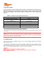
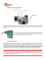
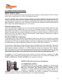
WARNING: The exhaust fan is the only way to ensure evacuation of combustion gases to the
outside. It is therefore very important to make sure it is in good condition and properly connected.
Inadequate evacuation is dangerous and can cause death. It can also prevent proper operation of
the device and void the warranty.
6.5) INGNITION SYSTEM SEQUENCE
This unit has a direct ignition system that monitors and controls flame ignition and gas valve. This system
uses an ignition distributor combined with the probe for detecting the flame. The flame is detected by the
method of correction works as follows: a weak electrical signal isolated from the ground is applied to the
detection probe through the ignition controller. When there is a flame in the immediate vicinity of the rod,
the flame acts as a conductor to the ground. It is said that the flame corrects and completes the circuit DC
which is automatically detected by the controller of ignition.
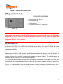
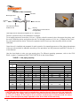
The ignition sequence is simple, but it must be understood before undertaking a
correction of a defective unit or new one. Following a thermostat demand, the
secondary circuit feeds a 24 volt relay. The relay produces a contact to start the
exhaust fan running on the current primary system 110 volts. Depending on the
exhaust fan applies a negative pressure on the pressure switch that closes the
secondary circuit and feeds the ignition controller. Pre-purge of 30 seconds
before ignition occurs. In series with pressure switch, there is two high limits of
air. If one of them is open, the circuit remains open and the ignition will not
occur. Then, the controller produces an ignition spark to the igniter and gas
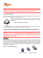
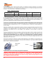
FIGURE 12 : ignition controller
valve opens simultaneously. The controller will wait a maximum of 7 seconds
for a flame detection before closing the valve. The controller will not attempt to
light the burner again if the lighting fails.
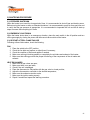
For the proper functioning of the flame sensing probe, a minimum signal of 1.5 microamps is required. It
can be measured with a microammeter. The spacing between the rod of the ignitor and the stem of the
ground must be 0.164 inch (4.17 mm). The igniter must be connected and grounded in ensuring continuity
between the burner and ignition controller. For more information on the ignition controller, refer to the
operation manual and installation of the controller provided by the manufacturer.
WARNING : The ignition system operates at high voltage. For safe handling, disconnect the power
before handling the ignition components.
24