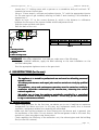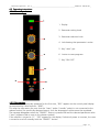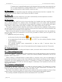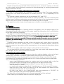
1
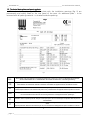
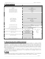
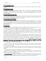
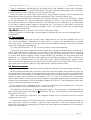
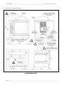
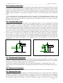
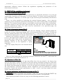
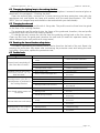
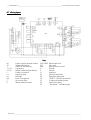
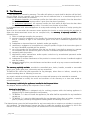
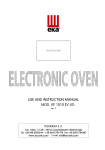
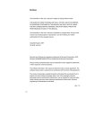
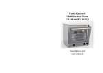
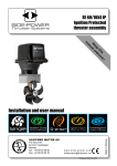
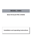
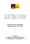
USE AND INSTRUCTION MANUAL
MOD. KF 1007
1007G UD
rev. 3
CATEGORY
GB
II2H3+
0705
TECNOEKA S.r.l.
Via I. Nievo, n.12/B - 35012 Camposampiero (Padova) Italy
Tel. +39.049.9300344 – +39.049.5791479 Fax +39.049.5794387
www.tecnoeka.com E-mail: [email protected]
__ TECNOEKA Srl _________________________________________________________ use and instruction manual _
Prodotti mirati per Ristorazioni, Pasticcerie,
Panetterie e Gastronomie
TECNOEKA Srl
Via I. Nievo, 12/B
35012 Camposampiero (PD)
Tel. +39 049 5791479 - +39 049 9300344
Fax + 39 049 5794387
www.tecnoeka.com – [email protected]
CE DECLARATION OF CONFORMITY
Annexed document II A, of directive 2006/
2006/42/E
42/EC
/EC
Manufacturer
Address
TECNOEKA Srl
Via I. Nievo, 12/B - 35012 Camposampiero (Pd)
Type of product
Model
Convection gas oven
KF 1007G
1007G UD
TECNOEKA Srl declares that the above mentioned products conform to the safety
regulations under:
CEI EN 60335-1
- Low voltage directive 2006/95/EC
CEI EN 60335-2-42
- Electromagnetic compatibility Directive 2004/108/EC
CEI EN 55014-1
CEI EN 55014-2
CEI EN 61000-3-2
CEI EN 61000-3-3
CEI EN 61000-4-2
CEI EN 61000-4-4
CEI EN 61000-4-5
CEI EN 61000-4-6
CEI EN 61000-4-11
-
Gas Appliances directive 2009/142/EC
Machine Directive 2006/42/EC;
Directive on the general safety of products 2001/95/EC;
Directive on the restriction in the use of dangerous substances in electrical
and electronic appliances 2002/95/EC;
- Directive on waste from electrical and electronic appliances 2002/96/EC.
Camposampiero, 30/05/2012.
___________________
Signature of a Representative of the Board of
directors
X:\Sgq\PRODOTTI\Fam. 1 - FORNI\FORNO GAS\LEka\MANUALI D'USO - Forno gas - LEka\Lingua
inglese\Instruction manual KF 1007G UD - GB - rev.3.doc
_ page. 2 ________________________________________________________________________________________
_ Convection gas oven _ rev. 3____________________________________________________ MOD. KF 1007G UD _
Index
1
Descriptions and general warnings
1.1
1.2
1.3
2
General instruction (for installation technician)
2.1
2.2
2.3
2.4
2.5
2.6
2.7
2.8
2.9
2.10
2.11
2.12
2.13
3
Place of installation
Transporting the oven
Unpacking the oven
Removing the protective film
Disposing of the packaging
Positioning
Gas connection
Electrical connection
Connection to water mains
Water outlet
Thermal breaker safety devices
Electronic circuit protection
Disposing of the oven
StartStart-up (for installation technician)
3.1
3.2
3.3
3.4
4
General warnings
Data-plate and warning-plate
Technical specifications
Check of nominal thermal capacity
Check of connection pressure
Adaptation to other gas
Injector replacement and adjustment of primary air
User instructions
4.1
4.1.1
General information
4.2
4.2.1
4.3
4.3.1
4.3.2
4.3.3
4.3.4
4.3.5
4.3.6
4.4
4.5
4.6
4.7
4.7.1
4.7.2
Operating instructions
Control panel
Operation mode
Cooking cycle ON/OFF
Displaying / changing parameters with the cooking cycle ON
Programmed mode
Saving cookin programs
Cooking with a saved program
Cooking with the “temperature at heart” function (for prepared ovens)
Door device
Black – out
First ignition
Cooking techniques
Steam cooking (moist heat)
Convection cooking (dry heat)
Residual risks
________________________________________________________________________________________ page. 3 _
__ TECNOEKA Srl _________________________________________________________ use and instruction manual _
4.7.3
5
6
Convection + humidity cooking (dry heat + moist heat)
Cleaning
5.1
5.2
General information
Cleaning the cooking chamber
5.3
5.4
5.5
5.6
5.7
Cleaning the fans
Cleaning the door seal
Cleaning the door
Cleaning the external casing
Periods without use
Maintenance
6.1
General information
6.2
6.3
6.4
6.5
6.6
Changing the lighting lamp in the cooking chamber
Changing the door seal
Resetting the thermal breaker safety device
Possible faults
Wiring layout
7
TECHNICAL ASSISTANCE AND ORIGINAL
ORIGINAL SPARE PARTS
7.1
Spare parts list
8
Informations to the consumers
9
The Warranty
_ page. 4 ________________________________________________________________________________________
_ Convection gas oven _ rev. 3____________________________________________________ MOD. KF 1007G UD _
1. Description
Description and general warnings
The model convector oven bears (KF 1007G UD) an official CE mark, issued by a Notified
Body, entrusted with and responsible for evaluating the observance of the essential
requirements specified by Gas Directive 90/396/EEC. The oven and the quality of the production
system are subjected to regular surveillance by means of inspection checks in order to ascertain
their conformity to the type certificate specified by the above mentioned Directive.
This appliance may be marketed in all the European countries whose abbreviated reference is
present on the technical data-plate. The appliance must be installed to conform with the local
laws on the installation of electrical-gas appliance for collective use, and shall include the
accessories and functional adaptations required in the destination countries, which are
described in the original language in the use and maintenance handbook.
The oven has an atmospheric burner and a heat exchanger for heating the cooking
compartment. Heat is diffused by an internal two-way fan. The parameters relative to cooking
(times, temperatures and climate) you set electronically and appear on the digital display.
It is possible to get steam inside the oven chamber. If the burner doesn’t switch on, a red
block light: it is possible to restart safely the ingnition of burner through the reset button. If the
oven chamber overheats, a safety thermostat blocks the gas delivery and the power to the oven
is cut off; it will be possible to switch it on again only manually. The device is located on the rear
of the unit.
1.1 General warnings
- If, on receipt of the goods, the packaging is damaged, write the following on the delivery
note: “I REVERSE THE RIGHT TO CONTROL THE GOODS”,
GOODS” specify the damage and get
the driver to sign in acceptance; send a claim in writing to the seller within 4 calendar
days from the date of receipt. No claim shall be accepted after such period.
- Read this handbook carefully: it supplies information on safe use, installation and
maintenance. The purpose of this manual is to provide information to operators on the
essential prescriptions and criteria to ensure their own safety and prolong the oven’s
operating life. This manual must be read by all personnel authorised to work on the
machine before it is started up. It must be stored together with the machine for all future
consultation. If the manual becomes worn or is mislaid, ask for another copy directly
from the manufacturer. These instructions are valid only for countries whose abbreviated
reference appears on the cover of this manual and on the data-plate. In European
countries where marketing is possible, manuals in the official language shall be provided
with specific references to gas, pressures, categories and conditions for the connection.
In European countries where marketing is possible, manuals in the official language shall
be provided with specific references to gas, pressures, categories and conditions for the
connection.
- Maintenance, adaptation to another type of gas, installation, and the functional check
must be performed only by qualified personnel authorised by the manufacturer. Install
the appliance in a suitable ventilated room and put it into operation while observing the
laws in force. Insist on original spare parts and, after replacing and/or adjusting a part,
such as primary air, make sure that it is sealed with paint to prevent any tampering. We
advise you to take out a maintenance contract.
- This appliance is designed for cooking or heating foods. Do not use it for other purposes;
all other uses are considered improper. The appliance is intended for collective and
professional use and must be utilised by personnel trained to use it.
- Before every oven cleaning or maintenance job, switch off electrical power, and shut off
gas and water supplies.
N.B.: Improper or incorrect use and failure to observe the installation instructions shall release the
manufacturer from all responsibility.
________________________________________________________________________________________ page. 5 _
__ TECNOEKA Srl _________________________________________________________ use and instruction manual _
1.2 Technical datadata-plate and warningwarning-plate
The technical data-plate (Fig.1) and the plate with the installation warnings (Fig. 2) are
permanently and visibly fitted on the rear panel of the oven. An additional plate – to be
removed with all packing material – is situated inside the packing.
Fig. 1
GB;
S.N.;
Fig 1
DE
“Dieses Gerat muß nach geltenden Vorschriften angeschlossen und darf nur in einem gut belufteten Raum betrieben
werden. Bitte beachten Sie vor Inbetriebnahme des Gerates die Gebrauchs- und Wartungsanleitung.“
FR
“L’appareil doit être raccordé conformément aux normes en vigueur et il ne doit être installé que dans locaux bien aérés.
Faire attention aux instructions relatives á l’utilisation et l’entretien de l’appareil avant de le mettre en marche.“
ES
“El apparato debe ser conectado conforme a las normas vigentes y se tiene que instalar solo en locales bien aireados.
Prestese especial atencion a las instrucciones para el luso y mantenimiento del apparato antes de ponerlo en marcha.”
GB
“The appliance must be connected according to the standards in force and must be installed only in well aired premises.
It is recommended to follow the use and servicing instructions of the appliance before operating it.”
PT
IT
O aparelho deve ser ligado em conformidade com as normas vigentes e deve ser instalado somente em locais bem
ventilados. Deve-se prestar particular atenção às instruções para o uso e a manutenção do aparelho antes de pô-lo em
funcionamento.
"L'apparecchio deve essere allacciato conformemente alle norme in vigore e deve essere installato solo in locali ben
aerati.
Si presti particolare attenzione alle istruzioni per l'uso e la manutenzione dell'apparecchio prima di metterlo in funzione."
Fig. 2
_ page. 6 ________________________________________________________________________________________
_ Convection gas oven _ rev. 3____________________________________________________ MOD. KF 1007G UD _
1.3 Technical specifications
Model
KF 100
1007G UD
External overall dimension L x D x H
Weight
Oven dimension L x D x H
Oven operational volume
Nominal thermal capacity
Tray maximal load (GN1/1)
Total load (10 trays GN 1/1)
ISO 7-1 gas union
Water union
Fume exhaustion vertical tube
Appliance category (for United Kingdom)
Factory adjustment
Type of construction
Electrical power
Electrical capacity
Class
Power cable type
965 x 885 x 1095 mm
148 Kg
604 x 458 x 608 mm
168 dm3
13 kW
4 kg
28 kg
1/2 “
3/4 “
Ø 150 mm; height min. 500 mm
II2H3+
Methane gas G20 a 20 mbar
A1 / B11
220-230 V ~
1,15 kW
I
H07RN-F 3 x 1,5 mm2
Connecting electric cable
Type Y
Gas connection pressure
Water connection pressure
Gas consumption calculated at low heat value of Hi at
15° and 1013 mbar
Liquid butane/propane gas G30/G31 : 30/37 mbar
Methane gas G20: 20 mbar
Max. 250 kPa (2,5 bar)
G30 : 1,03 kg / h
G20 : 1,38 m3 / h
Parameters to the chimney B11 (Ø 150 mm, L=0,5 m)
(G20 20 mbar)
fume load
25.5 g/s
fume temperature
220 °C
Parameters to the chimney B11 (Ø 150 mm, L=0,5 m)
(G30 28-30 mbar)
fume pressure
fume load
-1.4 Pa
24.2 g/s
fume temperature
231 °C
fume pressure
G 30/G 31 : 190 1/100 mm
G30/G 31 : 16 mm
-1.5 Pa
G 20 : 270 1/100 mm
G 20 : 10 mm
Main injector diameter
Primary air bush adjustment
Table 1
2. General instruction (for installation technician)
The installation technician must make sure that start-up conforms to current national
regulations. The appliance must be installed only by qualified personnel authorised by the
manufacturer. She must observe the safety regulations in force in the country where the
appliance is installed. All extraordinary maintenance jobs (possible adaptation to another type of
gas or replacement of parts) must be performed by qualified personnel having the necessary
professional qualifications.
The manufacturer will not respond for damage to people, animals and property due to
installation errors. Likewise the manufacturer is not responsible for breakage caused to the
appliance by incorrect installation.
2.1 Storage
If the appliance has been stored in a warehouse at a temperature below 0°C (min. allowed is
–20°C), it should be brought to a temperature of at least +10°C before it is turned on.
________________________________________________________________________________________ page. 7 _
__ TECNOEKA Srl _________________________________________________________ use and instruction manual _
2.2 Transporting the oven
During transport, the appliance must be left in its original wooden cage to protect it against
damage.
2.3 Unpacking the oven
Remove all the packaging before installation, which is formed of a wooden cage that holds
the appliance and cardboard casing to protect it. Check that the appliance has not been
damaged during transport and if any damage is discovered immediately inform your retailer
and/or the haulier.
2.4 Removing the protective film
Before using the appliance, carefully remove the special protective film over the stainless steel
parts, without leaving any glue residue on the surfaces. If necessary, remove the residue at once
with a suitable non-inflammable solvent (e.g. acetone).
2.5 Disposing of the packaging
The packaging must be disposed of in accordance with current legislation in force in the
place where the appliance is installed. The various types of materials (wood – paper – cardboard
– nylon – metal staples) used for the packaging must be separated and delivered to the specific
waste disposal centres. In all circumstances the environmental protection regulations must be
strictly adhered to.
2.6 Positioning
Positioning
Check the place where the appliance will be installed to ensure that the passages (doors and
corridors) are wide enough (the appliance measurements are given in Fig. 3).
The appliance must be installed in a well ventilated room with permanent ventilation
openings – if possible, it should be placed under an exhaustion hood ensuring complete
evacuation of burned gasses produced during baking. Locate the oven on a table or similar
support. We advise to use the support given by the manufacturer; otherwise you must consider
the weight of the oven. Never on the floor.
For easier access and to allow the air to circulate freely around the appliance, leave at least
50 cm between the left side and the wall (or other appliances), and at least 10 cm between the
back and the wall and the right side and the wall (see Fig. 3). The natural ventilation that is
needed to ensure efficient working for the oven is through the openings on the walls of the
outer covering (left side and back). Consequently, it is strictly forbidden to obstruct these
aeration openings, even partially and even for short periods. Failure to observe this specific
specific
prohibition, shall release the manufacturer from all liability for the appliance and shall
immediately cancel any guarantee rights for the said appliance, because its constructive
conformity has been voluntarily compromised.
For the same reason, do not position equipment with a source of heat on the left hand side
of the oven; in fact if ambient temperature on that side becomes too high, the oven switches
itself off for safety reasons
If the appliance is installed near walls, tops, shelves or other similar items, they must not be
inflammable or sensitive to heat, otherwise they must be protected by a suitable fireproof
covering.
In all cases, all fire prevention standards must be strictly adhered to.
With regards to the methods of discharging combustion fumes and in compliance with the
provisions of the local legislation for the installation of gas equipment, this oven can be
classified and therefore installed as follows:
Type A1 Installation: drawing the comburent air and discharging flue gases directly into the
installation room. This installation requires the working environment to be kept wholesome by
emptying the foul air and drawing fresh air through wall fans or extraction equipment.
_ page. 8 ________________________________________________________________________________________
_ Convection gas oven _ rev. 3____________________________________________________ MOD. KF 1007G UD _
Type B11 Installation: discharging the flue gases out of the installation room with a draughtdiverter compatible with a vertical tube (diam. 150 mm) making the discharge of the flue gases
into the extraction unit or directly into the building flue easy.
Since flue gases can reach high temperatures, pay particular attention not to overheat any
temperature sensitive elements (extraction equipment filters, electrical cables, etc.).
For the details regarding the installation (for instance minimum sections of ventilation, storing
of the gas canisters, etc.) see the applicable regulations in force in the country of destination.
Pay particular attention so that the volume of air required for the combustion is not obstructed
in any way by objects placed under or around the unit. The flow of air required to ensure the
correct combustion and the adequate change of air in the working place can be determined
with the following formula:
Q = 35 x P (where Q = air flow in m3 and P = heat input in kW).
If other equipment is fed with gas, the openings to ventilate the room must be enlarged as a
consequence.
2.7 Gas connection
Before installing, make sure that the oven is designed for use with the available gas. If it is
not, consult paragraph “Adaptation to other gas” or contact the manufacturer’s technical
assistance service. Connection to the gas mains must be made according to the current national
norm and subsequent amendments.
The oven gas connection is R 1/2; this entry section must not be reduced.
Connection to the gas supply line must be made by using rigid or flexible pipes, exclusively in
metal, with diameters in proportion to the power of the appliance and the length of the pipe
route. Make sure that the pipe does not pass close to the hot areas and that it is not subjected
to torsion and traction stresses. Install a rapid ON/OFF tap between the gas mains and each
appliance, in a position facilitating tap opening and shutting operations. After installing the
appliance, run a tightness test on the entire gas circuit, using a leak-detector spray or other
non-corrosive foam generating substances (do not use flames for this operation). The unions of
the copper pipes must be made by using mechanical couplings without seals.
2.8 Electrical connection
Connection to the electrical mains must be made according to the current legal regulations.
Before making the electrical connection, make sure that the voltage and frequency shown on
the rating-plate match those of the electrical supply system and that the latter is provided with
an efficient earth connection. The power cable used must not have lower characteristics than:
rubber insulated type H07RN-F with diameter of 3 x 1,5 mm2. If connection to the electrical
mains is permanent, a multi-core protective switch of adequate capacity must be installed, with
contact opening distance of the overvoltage category III (4000 V).. The yellow/green earth wire
must not be disconnected by the switch.
If the supply cable is damaged then it must be replaced by the manufacturer or by your
technical support or by a qualified person to avoid any risk.
The appliance must be part of an equipotential system - this connection is obtained with the
stop screw marked with the symbol
located at the rear. The diameter of the equipotential
wire must be 2,5 mm2.
When the appliance is operating, the supplied voltage must not deviate from the nominal
voltage value of ± 10%.
To replace the cable, cut off electrical power, and access the terminal board by removing the
oven rear panel. Locate the cables so that the earth conductor is the last to detach from its
terminal in the event of reverse pulling. Use an electrical cable with characteristics not below to
those mentioned above.
________________________________________________________________________________________ page. 9 _
__ TECNOEKA Srl _________________________________________________________ use and instruction manual _
Installation / connection layout
Fig. 3 (Dimensions in mm.)
_ page. 10 ________________________________________________________________________________________
_ Convection gas oven _ rev. 3____________________________________________________ MOD. KF 1007G UD _
2.9 Connection to water mains
The oven must be supplied with softened drinking water (see the respective signal next to the
connection solenoid-valve), with a hardness value of 0,5 to 5°F (it is mandatory using a water
softener to reduce the formation of scaling inside the boiler). The water pressure must be in the
range of 150 to 250 kPa (1,5 – 2,5 bar). If the water pressure exceeds 2,5 bar, install a pressure
reducer device upstream. If the pressure is below 1,5 bar, use a pressure pump to increase the
level.
The connection to the water supply is done using the ¾” threaded solenoid valve on the
back (at the bottom) of the appliance (see fig. 3), fitting a mechanical filter with a cut-off cock
(before connecting the filter, allow a certain amount of water to flow out in order to remove
any waste from the pipe).
2.5 cm
min. 30cm
2.10 Connection
Connection Water outlet
There is a drainage pipe on the back of the appliance (see Fig. 3) for emptying the cooking
chamber. A pipe of at least 30 mm internal diameter (DN30) must be connected to this pipe
that is resistant to the steam temperature. To avoid throttling, we advise using a rigid pipe
without any elbow bends along its length. The pipe must have a constant inclination of at least
5% along its length (the length is that from the outlet pipe from the appliance to the drain and
must not exceed 1 meter overall). The outlet pipe must flow into an open drain on the floor
(Fig. 4). If not, there must be a difference in height between the outlet pipe on the appliance
and the drain of at least 30 cm (see Fig. 5) to ensure the water flows out correctly. Moreover
the minimum “air drop” must be 25 mm (distance between the discharge pipe coming from
the unit and the exhaust pipe socket). In conformity with hygiene regulations in force, the pipe
connected to the water outlet pipe on the appliance must not be directly in contact with the
outlet point.
max. 2 mt
max. 2mt
Fig. 4
Fig. 5
2.11 Thermal breaker safety devices
The appliance is supplied with a manually resetting thermal breaker to protect against
excessive, dangerous temperatures which could be accidentally generated inside. If it is tripped,
the device cuts off the power supply to the appliance.
The device is located on the back of the unit and is identified by a suitable label (Fig. 3). The
reset button can be activated after unscrewing the black plastic cover and letting the oven cool
down
2.12 Electronic circuit protection
The electronic circuit inside the electric components compartment is protected by fuse.
2.13 Disposing of the oven
The oven is made with recyclable raw materials and does not contain any toxic substances
hazardous to people or the environment. Its disposal, as well as the disposal of its packaging,
must be carried out in compliance with the regulations in force in the place where it is installed.
The different materials that make it must be divided into types of disposal and given to the
________________________________________________________________________________________ page. 11 _
__ TECNOEKA Srl _________________________________________________________ use and instruction manual _
appropriate collection centres. Follow the regulations regarding the protection of the
environment at all times
3. STARTSTART-UP (for installation technician)
technician)
3.1 Check of nominal thermal capacity
The nominal thermal capacity must be verified by an authorised technician or by the gas
supply Body, observing the information in this use manual. This check must be performed for
new installations, adaptation to another type of gas and during all extraordinary maintenance
jobs.
There is no other possibility of adjusting the nominal thermal capacity – this is done by
measuring correct connection pressure and checking if the injector being used is of appropriate
diameter. The nominal thermal capacity is controlled by using a gas meter and a chronometer.
The exact volume of gas that must flow through per time unit can be obtained from the
technical specifications table. This value must be maintained in the specified range, the
permissible tolerance being ±5%.
3.2 Check of connection pressure
pressure (Fig. 6)
6)
The connection pressure is measured, with the unit working, using a pressure gauge for
liquids (for instance a liquid-level gauge with a minimum resolution of 0,1 mbar). To carry out
this test, remove the back of the unit and connect the “T” hose of the “M” gauge to the “P”
inlet pressure tapping point of the gas solenoid valve, after unscrewing the tapping point screw.
Measure the connection pressure: if this value
is not in the range shown in table 2 and it cannot
be brought within these values by adjusting the
pressure reducers of the gas supply system,
definitive start-up of the appliance is quite
impossible.
The gas supply Body must be informed about
this..
Type
Type of gas
Methane gas H G20
LPG gas G30/G31
Gas pressure (mbar)
Normal
Minimum Maximum
20
17
25
30/37
20/25
35/45
P
P re
ssio
ne
H2
mm
O
1100
1000
900
800
T
700
600
500
400
M
300
Key:
T = Hose
M = “U” pressure gauge
P = Pressure taketake-off at entry of gas solenoidsolenoid-valve
Table
Table 2
Fig. 6
After you have measured the connection pressure, disconnect the hose “T” and screw the
tightness screw of the pressure take-off “P”.
3.3 Adjustment to Other Gas
To adapt the oven to a type of gas that differs from the one tested in the factory (see
technical data plate), replace the injector of the main burner and adjust primary air inflow with
the adjustment bush. For this, disconnect the power and, after removing the back panel, access
the burner and the primary air adjuster. If you do not have the necessary spare parts, contact
the manufacturer’s technical assistance service. Adaptation must be effected by qualified
personnel. Consult the technical specifications in table 1 and 3, and then replace the main
injector and adjust primary air.
3.4 Injector replacement and adjustment of
of primary air (Fig. 7)
WARNINGS!
WARNINGS! Before you attempt this operation, make sure you shut off the gas ON/OFF tap
located upstream of the appliance and disconnect electrical power to the appliance.
After removing the back of the unit, carry out the following operations in series:
_ page. 12 ________________________________________________________________________________________
_ Convection gas oven _ rev. 3____________________________________________________ MOD. KF 1007G UD _
-
Loosen the “V” locking screw with a spanner or a screwdriver and pull out bush “B“
towards the burner Venturi pipe.
Using a 13 mm wrench, unscrew and replace injector “U” with the appropriate injector
for the new type of gas installed, referring to table 3 and checking if the diameter is
stamped on it.
Adjust air bush “B” to the correct distance H, which is the distance in millimetres
between the flat seat of the injector-holder and the adjustment bush.
Seal the screw and bush with paint.
Refit the back of the unit.
U
V
B
T
H
Gas
G30/G31
G20
Pressure
30/37 mbar
20 mbar
Injector diameter
190
190 1/100 mm
270 1/100 mm
Distance H
16 mm
10 mm
Table 3
Key:
B = Primary air bush
T = Burner Venturi tube
U = Injector
V = Bush securing screw
Fig. 7
WARNINGS! After every adaptation to a new gas, make sure of the following:
- Using an indelible adhesive, apply the data referring to the new installation on the
technical data-plate.
- Run the appropriate tightness tests on the gas circuit.
4. USE INSTRUCTIONS
INSTRUCTIONS (for the user)
ATTENTION!:
- The appliance is in tented for professional use and must be utilised by personnel
trained to use it.
- All ordinary maintenance and repair jobs must be carried out strictly by qualified
personnel.
- All installation, setset-up and maintenance operations must be carried out strictly by
installation technicians authorised by the manufacturer, observing the current
national regulations.
regulations.
- We advise you to have the appliance periodically controlled by a specialised
technician in order to keep it perfectly efficient – to this end, you are recommend
to sign a maintenance contract.
4.1 General Information
- When using the oven for the first time, we advise you to run it load-free at maximum
temperature for about one hour. In this way, any unpleasant smells, due to thermal
insulation, and grease residue from assembly are eliminated.
- Make sure that nothing prevents air from flowing into the burner and, in general, into
the ventilation of the room. Do not obstruct the burned gasses outlet or the oven flue,
and do not place any objects over these points.
- Check regularly the efficiency of the extraction unit, the exhaust pipes and the building
flue (no soot for instance).
________________________________________________________________________________________ page. 13 _
__ TECNOEKA Srl _________________________________________________________ use and instruction manual _
Survey the oven while it is in operation
Shut the gas and water ON/OFF taps upstream and disconnect electrical power when you
have finished using the oven.
- This appliance must be exclusively used for the purposes for which it was expressly
designed, i.e. cooking foods in the oven, any other use is improper.
The oven can be used for all oven cooking of pastry, bakery and gastronomy products, fresh
and frozen, for re-conditioning refrigerated and deep frozen foods, for steam cooking meat,
fish and vegetables.
When placing food in the cooking chamber, allow a space of at least 40 mm between pans
to avoid over-obstructing the airflow.
Do not use pans with edges higher than necessary: the edges act like barriers preventing
circulation of hot air.
Pre-heat the oven before each time it is used to guarantee the best performance.
For the cooking to be as even as possible, place the food evenly in each pan, considering the
size of the pieces, layers or the thickness.
Do not salt the food when it is in the cooking chamber.
To check the cooking cycle is proceeding correctly use the internal light in the chamber do
not open the door if it is not necessary, to avoid wasting energy and prolonging cooking
times.
Do not tamper with the devices sealed by the manufacturer; any tampering is forbidden and
dangerous. The misuse of this unit and partial or total failure to follow these instructions
release the manufacturer from all responsibilities for any damage to property or injury to
people.
-
-
-
-
4.1.1 Residual risks
After a cooking operation, open the door cautiously, to avoid a violent outflow of heat which
could cause burns.
While the oven is in operation, pay attention to the hot zones (marked on the appliance) of
its external surfaces.
The bench or support must be able to support the weight of the machine and house it
correctly.
The appliance contains electrical parts and must never be washed with a jet of water or
steam.
The appliance is electrically connected: before attempting any cleaning operation, cut power
to the appliance.
To prevent incorrect connection of the appliance, the relevant electrical, gas and water
connections are marked by identification plates.
_ page. 14 ________________________________________________________________________________________
_ Convection gas oven _ rev. 3____________________________________________________ MOD. KF 1007G UD _
4.2 Operating instructions
4.2.1
4.2.1 Control panel
1
1. Display
2. Parameter setting knob
3. Parameter selection knob
2
4. led showing that parameter is active
5. Key “reset” gas
6. button to save programs
3
7. Key “ON / OFF”
4
5
6
7
4.2.2
.2.2 First ignition
When the oven is electrically powered for the first time, "ER2" appears on the control panel display
accompanied by a brief acoustic "BEEP".
This way the oven warns the user that the “heart” probe (“needle” probe) is not connected to the
relevant socket (for specifically designed ovens), thus the temperature value cannot be regulated.
The message disappears when the “ON/OFF” button is pressed ON and the selected parameter value
(“zero”) appears (Led on next to the relevant symbol).
If the selector is turned to “0”, “OFF” appears on the display. If electrical power is constant, the oven
is turned on and off normally with the "ON/OFF" button.
________________________________________________________________________________________ page. 15 _
__ TECNOEKA Srl _________________________________________________________ use and instruction manual _
4.3 Operation mode
The cooking cycle can be run in “manual” or “programmed” mode.
Each cycle is made up of several cooking parameters: time/temperature/humidity/”heart”
temperature (for specifically designed ovens)/half motor speed/half power.
MANUAL MODE
To select cooking parameters, turn the selector to the selected parameter (see symbol). To set or
change the selected parameter value, rotate the regulator knob clockwise (to increase) or counterclockwise (to decrease).
) can be set from 0 hours and 1 minute to 9 hours and 59
The “time” parameter (symbol
minutes. If "INF" appears on the display this mean the timer is not set and the oven will operate
continuously until manually turned off by pressing the "ON/OFF" button.
The “temperature” parameter (symbol
) can be set from 50° C to 270° C.
The “humidity/steam” parameter (symbol
) can be set from 1 to 10 (10=100%).
The “temperature at heart” parameter (symbol
designed ovens).
) can be set from 0° C to 100° C (for specifically
IN ORDER FOR THE “TEMPERATURE AT HEART” PARAMETER TO WORK, IT MUST BE SET BEFORE
BEFORE THE COOKING
COOKING
CYCLE STARTS, AND THEN, BEFORE YOU SET THE TEMPERATURE
TEMPERATURE PARAMETER IN THE COOKING CHAMBER
CHAMBER.
AT LEAST COOKING TIME AND TEMPERATURE PARAMETERS
PARAMETERS MUST BE SET FOR
FOR THE COOKING CYCLE TO START.
4.3.1 Cooking cycle ON/OFF
When the door is closed, the cooking cycle automatically starts 5 seconds after setting the two
parameters required for cooking (time/temperature).
The lights in the cooking chamber, the resistance and motors turn on.
When the set cooking cycle time has elapsed, the oven automatically turns off, the set parameter
values clear on the display and an acoustic signal sounds for 3 seconds. The oven readies for new
cooking cycle settings.
The cooking cycle can be stopped at any time by pressing the “ON/OFF” button “OFF”.
The display turns off and an acoustic signal sounds for 3 seconds.
4.3.2 Displaying / changing parameters with the cooking cycle ON
When the cooking cycle is on, parameters can be displayed by turning the selector knob to the
relevant symbol.
Parameters can be changed by turning the regulator knob.
- “Time” parameter
The cooking cycle count down is displayed (blinking led on symbol
- “Temperature” parameter
The set value (fixed led on symbol
).
) is displayed for 3 seconds alternated by the value
measured inside the cooking chamber for 3 seconds (blinking led on symbol
- “Humidity/steam” parameter
The set value is displayed (fixed led on symbol
- “Temperature at heart” parameter
The set value (fixed led on symbol
read inside the food for 3 seconds.
).
).
) is displayed for 3 seconds alternated by the value
“AT HEART” TEMPERATURE CANNOT BE
BE SET OR CHANGED WHEN
WHEN THE COOKING CYCLE IS ON.
It can only be displayed if the "needle" probe (connected to the specific socket) is inserted in food.
For the user’s convenience, when the selector is turned to “O”, the cooking cycle count down
will be displayed for 3 seconds alternated by the temperature measured in the cooking chamber for 3
seconds.
_ page. 16 ________________________________________________________________________________________
_ Convection gas oven _ rev. 3____________________________________________________ MOD. KF 1007G UD _
4.3.
4.3.3
3.3 Programmed mode
Up to 10 cooking programs (cycles) can be saved.
Each program can be made up of several cooking parameters.
4.3.
4.3.4
3.4 Saving cookin programs
Following the steps below to save a cooking program (with the oven on: “On/Off” button pressed):
Leave the oven door open (to prevent parameter settings from automatically starting
the cooking cycle).
Set the relevant cooking cycle parameters following the same procedure used for
“manual” mode.
Turn the selector to “o” (“oFF” appears on the display).
Turn the regulator knob and select the required program number (from P01 to P10).
-
Press and hold down the “ ” button for at least 5 seconds: the program is
successfully saved with the saved program number blinks on the display.
The saved program and cooking cycle start when the oven door is closed.
To cancel a saved program, simply replace it with a new program (with the same
number) where new parameters are set for the new cooking cycle. The new program
must be saved by pressing the “
” button.
4.3.
4.3.5
3.5 Cooking with a saved program
Following the steps below to recall a cooking program (with the oven on: “On/Off” button pressed):
- Turn the selector to “O” (“oFF” appears on the display).
- turn the regulator knob and select the required program number.
If the door is closed, the cooking cycle automatically starts 5 seconds after the program number is
selected.
When the oven is operating in “programmed” mode, set parameters can be displayed in the same
way as with “manual” mode.
For the user’s convenience, set parameters can be changed during oven operations in “programmed”
mode. At the end of the programmed cooking cycle, changed parameters are automatically “RESET”
and return to the values initially saved in the program.
4.3.
4.3.6
3.6 Cooking with the “temperature at heart” function (for prepared ovens)
The temperature can be set inside the core of the food to be cooked, using the special needle
core probe. The probe must be pushed into the centre of the food in the thickest part, avoiding
the bones. Place the food inside the cooking chamber and pull out the thermal probe lead and
close the oven door. The probe plug must be plugged into the special socket (see Fig. 1) at the
bottom of the control panel.
When the "at heart" probe is turned on during the cooking cycle, turning the selector to the
"time" parameter (symbol
), "Prb" will appear on the display (confirmation that the “at
heart” probe is on).
For the user’s convenience, turn the selector to “O” and "Prb" will be displayed for 3 seconds
alternated by the temperature measured in the cooking chamber for 3 seconds.
The cooking cycle ends as soon as the temperature read by the “needle” probe (inserted in food)
reaches the value set in the “temperature at heart” parameter (regardless of the value set in the
“time” parameter).
The oven automatically turns off, the set parameters reset on the display and an acoustic signal
sounds for 3 seconds.
The oven readies for a new cooking cycle.
Warning: Before removing the food from the oven after cooking with the core needle probe.
Warning
Carefully remove the hot probe from the cooked food, taking care not to leave it
hanging out of the cooking chamber as it could cause burns.
We advise leaving it to cool down before using it again – to avoid damaging pricks in
the food.
________________________________________________________________________________________ page. 17 _
__ TECNOEKA Srl _________________________________________________________ use and instruction manual _
To prevent any irreparable damage to the thermal piercing probe (core probe) do not
use it in high temperature cooking ABOVE 230°C, and ensure that the probe lead is
not touching any hot metal surfaces inside the oven.
4.4 Door device
The device stops oven operations (stops the cooking cycle) whenever the door is opened. The
cooking cycle resumes where it left off when the door is closed.
4.5 Black - out
When power returns after a black-out, the oven automatically resumes operations and the
cooking cycle resumes from where it left off.
4.6 First ignition
The oven can be used for the first time only after the chamber has been carefully cleaned
with a special detergent for stainless steel. The detergent must not contain acid substances
(chloride acid, bleach, etc.) or be abrasive. Alternatively the chamber can be washed with warm
soapy water or warm water and a drop of vinegar. Rinse well and dry with a soft cloth.
First ignition (without food inside the oven) serves to eliminate any unpleasant smells (which
are quite normal) due to the thermal insulation heating up that covers the cooking chamber and
any oil residues from assembly of the metal parts.
After turning the power on (close the unipolar switch fitted upstream from the appliance),
and the water (open the interception cut-off cock), proceed as follows (see the figure of the
control panel):
- press the on/off push button;;
-
set the time (knob on the symbol
) at one hour (shown on the display);
-
set a temperature (knob on the symbol
) of 270°C for the cooking chamber (shown
on the display);
- check the door is closed;
- the cooking chamber starts automatically to heat up after 5 minutes when the
temperature is set.
When the time is up, the oven turns off automatically and the beeper sounds for 03 seconds..
4.7 Cooking techniques
There are three different cooking techniques: steam, convection and convection & humidity.
4.7.1 Steam cooking (moist heat)
The climate regulation system which allows dividing the humidity production which should be
set at 10 (humidity \ continuous steam) , while the cooking chamber temperature can be set
between 105°C and 115°C.
Steam cooking is indicated where a boiled effect is required, and it has the advantage of
leaving the nutritional content of the food unaltered (the vitamins and flavour of the food are
conserved), the outer appearance (the colour is conserved, no lumps or air bubbles are formed
and the surface does not break up) and the weight is conserved, as no liquids are lost from the
food during cooking.
4.7.2 Convection cooking (dry heat)
The heating elements heat the dry air inside the cooking chamber. This heated air is evenly
distributed by the high speed of the fans. This gives an even temperature throughout the
cooking chamber and even cooking even when the oven is full.
This means that different types of food can be cooked on the various shelves (as long as they
need the same cooking temperature) without flavours and smells being mixed together.
The cooking chamber temperature can be set between 50°C and 270°C.
_ page. 18 ________________________________________________________________________________________
_ Convection gas oven _ rev. 3____________________________________________________ MOD. KF 1007G UD _
Besides evenly browning the food without having to turn it, convection cooking can be used
to cook au gratin and is particularly convenient for rapid defreezing, for sterilising preserves and
drying mushrooms and fruit.
4.7.3 Convection + humidity cooking (dry heat + moist
moist heat)
This type of cooking exploits the combination of dry and moist heat. The climate regulation
system which can divide the production of humidity (set from 1 to 10 depending on the
request).
The cooking chamber temperature can be set between 50°C and 270°C.
The fact of using a hot-moist climate inside the cooking chamber is the most convenient and
efficient way of cooking: cooking times are reduced, the surface of the foods remains soft and
does not form a crust, there is little weight loss and the fatty mass is reduced.
The special hot-moist climate at low temperatures is ideal for re-conditioning food.
5. Cleaning
5.1 General information
Before beginning any sort of cleaning work on the appliance, turn the power supply off (at
the magnetothermal safety switch) and the water supply (by closing the cut-off cock) and then
let the oven cool down completely.
The appliance must be cleaned frequently, preferably daily, to guarantee best operations and
long life. The oven is equipped with electrical components therefore for obvious reasons water
should not be used in excess for cleaning. However, it is absolutely forbidden to wash the
appliance with water jets, especially if they are pointed towards the aeration vents on the metal
surface of the outside casing (this could cause dangerous infiltrations that would damage the
electric parts).
If grease remover detergents are used to clean the stainless steel, ensure they do not contain
corrosive acids (no sort of chlorine, even if it is diluted) or abrasive products. Follow the
indications given on the product and the warnings about its use, wearing rubber gloves during
cleaning.
Do not use iron pads, steel wool or scrapers as they would ruin the surfaces.
Do not leave food on the steel surfaces for a long time that contain acid substances (lemon
juice, vinegar, salt, etc.) as they could cause corrosion.
5.2 Cleaning the cooking chamber
For hygienic reasons, it is good practice to clean the cooking chamber at the end of each
cooking cycle, otherwise it should be cleaned at least once at the end of each day’s use.
For easier cleaning, remove the side grills by unscrewing the 4 fixing screws (hold the reeded
nut between your thumb and forefinger and turn it in an anti-clockwise direction) and please
carry out the following operations:
- spray a special degreasing product for stainless steel on the external walls, on the fan
casing (do not spray it through the fan grids) and on the glass inside the door;
- leave the product to work for approximately 20 minutes with the door closed;
- turn the oven on to 70-80°C;
- run a cycle with maximum steam (knob “humidity\steam on 10) for around 15 minutes;
- when the cycle is over, switch the oven off, let the oven chamber cool down and flush
with plenty of water (use the shower provided)
- Dry with a soft cloth or run a heating cycle, with the temperature at 150-160°C for
about 10 minutes (the cycle can be repeated if necessary).
The side grills and drainage plug must be cleaned separately and then replaced.
When cleaning is terminated, leave the oven door slightly ajar.
________________________________________________________________________________________ page. 19 _
__ TECNOEKA Srl _________________________________________________________ use and instruction manual _
5.3 Cleaning the fans
The fans must be periodically cleaned with specific anti-limescale products. All the parts must
be carefully cleaned, removing all limescale deposits.
To access the fans, remove the fan carter after unscrewing the relative screws (with knurled
ring nuts) securing it to the oven chamber.
5.4 Cleaning
Cleaning the door seal
For Hygiene and functionality’s sake, clean the door seal at the end of each working day. It
must be washed carefully with soapy lukewarm water. Rinse and dry with a soft cloth. Any food
deposit or residue must be removed carefully, without using any sharp metal tools that might
damage the seal irreparably.
5.5 Cleaning the door
The glass on the door inside the cooking chamber can be cleaned with the same degreaser as
used for cleaning the chamber or a normal glass cleaning product can be used (non toxic).
Normal glass cleaning products can also be used to clean the glass on the outside of the door,
or simply warm soapy water, rinse and then dry the glass well with a soft cloth.
If dull marks form between the two door glasses, these can be removed by dismantling the
external glass.
To do this act on the appropriate hooks for closure of the glass.
After cleaning the glass close the external glass acting on reverse.
5.6 Cleaning the external casing
The external steel surfaces should be cleaned with a cloth soaked in warm soapy water or
with a drop of vinegar added, they should be rinsed well and dried with a soft cloth.
If you use specific cleaning products, they must correspond to the requirements for cleaning
given in the paragraph “General information”.
You should also remember that the table the appliance stands on or the surrounding floor
should not be cleaned using corrosive acid products (for example muriatic acid), as the fumes
that are given off could attack and damage the external steel casing and damage the electrical
components inside the unit irreparably.
5.7 Periods without use
If the appliance is not used for a long time, it is good practice to unplug it from the mains (at
the magnetothermal safety switch upstream from the appliance) and to turn off the water with
the cut-of cock on the main supply line. It should be carefully cleaned inside the cooking
chamber and outside, taking special care to remove any salt deposits which would cause
corrosion to the steel surfaces.
We also advise protecting the appliance with an oily base spray (e.g. Vaseline oil), which
forms an effective protective film on the surface of the steel.
A suitable covering would also protect the appliance from the dust.
6. Maintenance
6.1 General information
A periodic control (at least once a year) of the appliance aids to guarantee long life and
correct operations.
Any sort of maintenance work on the appliance must be done exclusively by technically
qualified operators who have been trained in the maintenance work on this appliance.
Before beginning any sort of maintenance work on the appliance, turn the power supply off
(at the magnetothermal safety switch upstream from the appliance) and let it cool down.
The components that might require maintenance are all accessible by removing the left hand
side and the back of the unit.
_ page. 20 ________________________________________________________________________________________
_ Convection gas oven _ rev. 3____________________________________________________ MOD. KF 1007G UD _
6.2 Changing the lighting lamp in the cooking chamber
The lamp is housed between the two door glasses; to replace it remove the external glass as
described in the paragraph: “Cleaning the door”.
Open the external glass, unscrew the 2 screws securing the lamp protection cover with the
appropriate tool and replace the lamp with another with the same specifications: 12V 35W
300°C (this is a halogen lamp and should not be touched with your bare hands)
6.3 Changing the door seal
The door seal has a rigid profile with 4 fixing tabs. The profile must be fitted into the guide
on the face of the cooking chamber.
The rectangular seal fits perfectly into the frame of the guide and, therefore, the seal profile
fits perfectly onto the face of the cooking chamber.
To change the seal, remove the old one from the guide by pulling hard at the four corners.
Clean any dirt from the guide and introduce the new seal (to make this operation easier, we
advise dampening the seal profile with soapy water).
6.4 Resetting the thermal breaker safety device
This device (identified by the relative sticker) can be found on the back of the unit. Reset it by
pressing the red button fully down after unscrewing the protective cover and letting the oven
cool down. Once done, replace the protective cover.
6.5 Possible faults
Type of fault
Control panel completely off
(the oven does not work)
Cooking cycle set and START
push button pressed: the oven
does not work
Humidity\steam cycle ON: no
humidity\steam is produced in
the cooking chamber
Cause
- Incorrect electric connections to the
mains
- No mains voltage
- Thermal break safety device tripped
- Electronic card protection fuse
(microprocessor ) burnt
- Door open or ajar
- Device (switch) damaged door
- Incorrect connection to water mains
- Cut-off cock closed
- Blocked water inlet filter
- Damaged water inlet solenoid
- Seal not fitted correctly
Door closed: steam comes out
of the seal
- Damaged seal
- Handle prong loosened
The oven does not cook evenly
- One of the motors is blocked or turns
slowly
- The motors do not go into reverse
Lighting lamp in the cooking
chamber does not work
Corrective action
- Check the mains connection
- Restore mains voltage
- Reset the thermal break safety device
- Contact a qualified technician
- Close the door
- Contact a qualified technician to repair
the sensor
- Check the connection to water mains
- Check the cut-off cock
- Clean the filter
- Contact a qualified technician to repair
the solenoid
- Check the seal fitting
- Contact a qualified technician to repair
the seal
- Contact a qualified technician to repair
the prong
- Contact a qualified technician to repair
the motor
- Contact a qualified technician to repair
the motor
- Damaged lamp
- Change the lamp
- Damaged lamp feeder
- Contact a qualified technician to repair
the feeder
________________________________________________________________________________________ page. 21 _
__ TECNOEKA Srl _________________________________________________________ use and instruction manual _
6.7
6.7 Wiring layout
Key
M
T1
T
C1-C2
V1-V2
I
L1
L2
MI
F
E
Power supply terminal board
Safety thermostat
230/12V transformer
Capacitors
Radial motorised ventilators
Power line switch
Lighting lamp
Led light
Door microswitch
Anti-noise filter
Water solenoid-valve
SM1-SM2
SG
SMI
D
S
R
E1
E2
IR
S1
S2
S3
Motorised card
Gas card
Microprocessor card
Display
Selector
Regulator
Ignition electrode
Detection electrode
“RESET” GAS button/switch
Cooking chamber probe
Food core probe
“No flame ” indicator-light
_ page. 22 ________________________________________________________________________________________
_ Convection gas oven _ rev. 3____________________________________________________ MOD. KF 1007G UD _
7. TECHNICAL ASSISTANCE AND ORIGINAL SPARE PARTS
Before leaving the factory, this appliance was tested and set up by expert, specialised
personnel, to ensure best operating results. Any eventual assistance or regulation must be done
with maximal care and attention, using original spare parts.
For this reason it is necessary to apply to the distributor that has done the sale, specifying
the type of inconvenience and model of the appliance purchased. The required parts for
different gas type adaptation are available along with the appliance at the moment of sale or
delivery.
For any maintenance the user can contact Tecnoeka by calling the telephone numbers on
the cover or going to www.tecnoeka.com.
www.tecnoeka.com
7.1 Spare parts list
PART
Oven burner
Ignition/ detection plug
Power cable
Electronic control unit
Condenser
Water solenoid-valve
Gas solenoid-valve
Anti-noise filter
Power supply terminal board
Oven ventilation motor
Lamp holder
Microprocessor card
Motorised card
Safety thermostat
Transformer
TECNOEKA CODE
09986427000
09986287000
09950397000
11951037000
11950817000
11950957000
11951027000
11951477000
08950197300
11950807000
11950107000
11951517000
09986367000
01951367000
11950087000
8. Informations to the consumers
Further to Directive 2002/96/EC, the symbol of the crossed rubbish skip on
the appliance means that at the end of its life, the product must be
disposed of separately from the other rubbish. The user must hand the
appliance to a specialised waste collection centre for electric and electronic
equipment.
The separate collection of the rubbish and subsequent treatment, recovery and disposal help to
produce other equipment using recycled materials, reducing the negative effects on the
environment and public health, which would be caused by incorrect management of the
rubbish.
Should the user dispose of the product abusively, administrative sanctions would be applied.
________________________________________________________________________________________ page. 23 _
__ TECNOEKA Srl _________________________________________________________ use and instruction manual _
9. The Warranty
Your appliance is covered by warranty. The seller will replace or repair (and his decision will be final),
free of charge for the customer, only those parts that are defective due to a manufacturing fault on
condition that, under penalty of forfeiture:
− for domestic equipment, the customer notifies the fault within two months from the date when
he/she discovered it and anyway within 2 years form the date of purchase;
− for professional equipment, the customer notifies the fault within 8 days from the date when
he/she discovered it and anyway within 12 months from the date of purchase,
by registered letter with acknowledgement of receipt and enclosing the invoice or receipt proving the
purchase.
Apart from the case when the customer cannot produce the invoice or receipt proving the purchase or
when the above-mentioned terms are not complied with, the warranty is expressly excluded in the
following cases:
1) faults or breakage caused by the transport;
2) wrong or incorrect installation of the product (for instance because of insufficient draught of the
flue or exhausts) in light of the instructions given in the user’s handbook supplied with the
product;
3) inadequate or abnormal electrical, hydraulic and/or gas supplies;
4) carelessness, negligence or incompetence in using the product in light of the instructions given in
the user’s handbook supplied with the product;
5) use of the product for uses different from the one for which it was built or anyway in a manner
not compliant with the instructions given in the user’s handbook supplied with the product;
6) tampering with the product;
7) adjustments and/or maintenance and/or repairs carried out by unauthorised personnel and/or
with non original spare parts;
8) inadequate or careless maintenance of the product in contrast with the user’s handbook supplied
with the product;
9) damages caused by fire, natural disasters and accident as well as by any cause not attributable to
TECNOEKA SRL.
The warranty explicitly excludes:
excludes varnished or enamelled parts, knobs, handles, movable or removable
plastic parts, bulbs, glass parts, refractories and any accessories.
TECNOEKA SRL cannot be held responsible for any damages, either direct or indirect, caused by the
product breaking down or following its non-use.
Any repairs carried out during the warranty do not cause said warranty to be extended or renewed.
Nobody is authorised to modify the terms and conditions of the warranty or to issue new verbal or
written warranties.
The warranty is valid only for appliances installed in the European Union.
Any dispute shall be settled by the competent Court in Padua.
Warning for the Buyer:
1. the cooking appliance is designed only for cooking purposes while the heating appliance is
designed only for heating domestic environments;
2. TECNOEKA S.r.l. does not install the appliances; the seller shall be responsible for any installation
carried out;
3. TECNOEKA S.r.l. cannot be held responsible for any damages, either direct or indirect, to people,
pets or property caused by the appliance breaking down or following its non-use.
The Manufacturer cannot be held responsible for any inaccuracies due to misprints or mistakes in copying in
this handbook. The Manufacturer reserves the right to modify the products as he deems fit, also in the
interest of the user, without affecting the vital characteristics of functionality and safety.
_ page. 24 ________________________________________________________________________________________