1
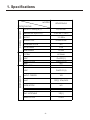
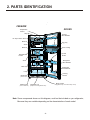
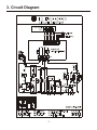
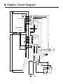
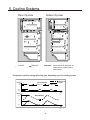
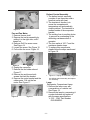
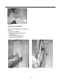
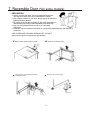
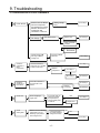
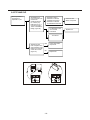
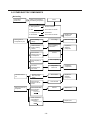
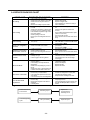
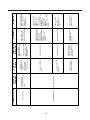
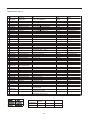
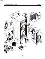
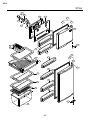
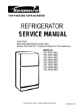
REFRIGERATOR
SERVICE MANUAL
CAUTION
BEFORE SERVICING THE UNIT,
READ THE SAFETY PRECAUTIONS IN THIS MANUAL.
MODEL: LRTN09314SW
Contents
SAFETY PRECAUTIONS
………………………………………………………………. 2
SERVICE PRECAUTIONS
………………………………………………………………. 3
1. SPECIFICATIONS
………………………………………………………………. 5
2. PARTS IDENTIFICATION
………………………………………………………………. 6
3. CIRCUIT DIAGRAM
………………………………………………………………. 7
4. GRAPHIC CIRCUIT DIAGRAM
………………………………………………………………. 8
5. COOLING SYSTEMS
………………………………………………………………. 9
6. DISASSEMBLY
………………………………………………………………. 10
7. REVERSIBLE DOOR(*ON SOME MODELS)
………………………………………………………………. 13
8. ADJUSTMENTS
……………………………………………………………….15
9. TROUBLESHOOTING
……………………………………………………………….17
10. DESCRIPTION OF FUNCTION & CIRCUIT OF MICOM
……………………………………………………………….23
11. EXPLODED VIEW & REPLACEMENT PARTS LIST
……………………………………………………………….39
Safety Precautions.
Read the following instructions before servicing your refrigerator.
1. Unplug the refrigerator before
servicing.
2. Visually inspect for gas leakage or
short circuit.
3. If testing with the refrigerator
plugged in, wear rubber gloves to
avoid electric shock.
4. Do not touch frozen metal parts;
your hands could freeze to the
surface. This may cause frostbite.
5. Be sure that no water is dripping
towards electrical or metal parts.
6. If you check the bottom part of the
refrigerator while the freezer
door is open, be careful standing
up. You could bump your head.
7. When you tilt your refrigerator be
sure to take out all metal, glass, or
other loose parts.
8. When servicing the evaporator,
wear cotton gloves to prevent cutting
by any of the evaporator fins.
-2-
Service Precautions
Refrigerant Recharging
Test the compressor's operation before
recharging the refrigerant; this is very
important to detect failures and to
ensure the proper motor running, and
to identify failures immediately. If
failure has been detected, clean the
system from any other possible
R-134a residues by breaking the final
part of the compressor's service pipe
at it's thinnest part as shown in Fig. #1.
Replace the filter and any other part
that could be deteriorated. Unweld
and pull out the service pipe,
then place a new pipe extension with a
Hansen male connector and solder
the new pipe. See Fig. #2
Punto que debe
Extensión de
ser quebrado
tubo para carga
0(absolute or -1 atm, -760 mm Hg.) It
is not recommend to run the vacuum
pump for more than 30 minutes. See
A la bomba de
vacío
Medidor de
presión
Fig.#3
Figure 3.
In case there is a large leak and the
vacuum operation must stop,
you must add a small amount of
refrigerant to the system and check
with an electronic leak detector. If a
soldering failure is detected, open the
valve before soldering to equalize the
pressure and keep solder from being
blown out of the joint or sucked into
the piping.
Con.
Hen.
Conector
macho
hansen
Extensión de tubo de servicio
Fig. # 1
Punto de Soldadura
As soon as the repair is completed,
charge the correct amount of
refrigerant into the system.
Remember that each system requires
a specific amount of refrigerant with a
tolerance of ±5 grams. See Figure 4.
Fig. # 2
It is necessary to open the valve
when soldering to allow the gases to
escape without forcing the molten
solder out of the joint. The extension
with the male Hansen connector
should be connected to a female type
connector to the vacuum pump's pipe.
See Fig. #3
System air evacuation starts as soon
as the pump begins to run. The
system must be kept under vacuum
until the low pressure gauge shows
Al cilindro de R-134a
Al sistema de
refrigeración
Fig. #4
Fig. # 4
Before performing this operation (if
the vacuum pump and charging
cylinder are still attached to the
system) be sure the valve between
the pump and the cylinder is closed to
-3-
keep refrigerant out of the system.
See Figure 5.
For gas charging, check the
graduated scale on the cylinder to see
the amount of refrigerant that it
contains and the amount that will be
pumped into the system. For
example, if you have 750 grams of
refrigerant in the cylinder and we
have to pump 165 grams to the
system, this amount will be reached
when the indicator reaches 585
grams; remember that the indicator
shows a lower level of meniscus.
installed in one session, as it could
block the compressor. Install 20~30
grams at a time and close the valve.
The compressor will run and the
pressure will drop. Then open the
valve and install other 20~30 grams
of refrigerant. Repeat this procedure
until the entire amount has been
added to the system. Under operating
conditions, the system pressure
should stabilize between 0.3 and 0.6
atm.
Fig. # 5
Tubo de carga del
refrigerante
Do this after choosing the scale
corresponding to the gas pressure
indicated on the pressure indicator
located on the upper part of the
column. To let R-134a flow into the
system, open the valve at the
recharging cylinder's base. The total
amount of refrigerant should not be
La válvula debe ser abierta
cuando se recargue el gas
Al sistema del
refrigerador
Al cilindro
de carga
Válvula debe ser
cerrada después de
lograr el vacío
A la bomba de vacío
Fig. # 5
-4-
1. Specifications
MODELS
LRTN09314SW
SPECIFICATIONS
REFRIGERATOR
FREEZER
GENERAL FEATURES
CAPACITY litros(F/R/T)
61/180*241
DIMENSIONS in(W*H*D)
21.45*64.17*24.21
WEIGHT
121.25Lb
HANDLE TYPE
HORIZONTAL
REVERSIBLE DOOR
NO
DOOR FINISH
PCM
REFRIGERANT
R134a
ICE TRAY
NORMAL
SHELF
PLASTIC(1)
BASKET DOOR
LAMP
TRAY MEAT
PLASTICO(2)
NO
YES
SHELF
PLASTICO(2)
MAGIC CRISPER
YES
LAMP
YES(1) 20W/AZUL
GUIDE BOTTLE
NO
DOOR COOOLING
NO
TRAY VEGETABLE
YES(1)
BASKET DOOR
4 FULL
-5-
2. PARTS IDENTIFICATION
FREEZER
DOORS
Temperature
Control
Lamp
Freezer
Door Baskets
Ice Trays ¨Twist´n Serve¨
Bank Ice
Egg Tray
Shelf
Door Cooling
Bank Ice
Guide
Bottle
Temperature
Control
Shelf
Refrigerator
Door Baskets
Meat Tray
Refrigerator
Door Baskets
Lamp
Leveling
Screws
Deodorizer
(Absorbs olors)
Multi Air Flow
(Air flow distributor)
Magic crisper
Vegetable Tray
(Keeps fruits and vegetables fresh)
(Vegetable Tray cover with humidity control)
Note: Some components shown on this diagram, could not be included on you refrigerator;
Because they are variable depending on the characteristics of each model.
-6-
3. Circuit Diagram
THE PLUG TYPE, CAPACITOR , F-LAMP & F-DOOR S/W , R-LAMP2 AND COMPRESSOR
EARTH PARTS ON CIRCUIT DIAGRAM ARE SUBJECT TO CHANGE IN DIFFERENT
LOCALITIES AND ACCORDANCE WITH MODEL TYPE.
WHEN STARTING CAPACITOR IS NOT USED, NO. 3,4 OF PTC START ARE CONNECTED
INTERNALLY.
-7-
4. Graphic Circuit Diagram
Fan
Bla c k
White
White
c
Blue
Blue
Red
Thermal Fuse defrost
Resistance (Heater cord)
Red
C
Red
Brown
Red
Brown
C
Orange
Sensor
Orange
Evaporator
Bro wn
Re d
Sensor
Red
Brown
Defrost resistance
(Heater plate)
Oranje
Oranje
Yellow
Switch
Blac k
Violeta
CON2
Brown
Control
Red
Pink
Yellow
Sensor
Blue
Violeta
White
White
Defrost and
Temperature
Electronic
Control
Blue
CON1
Yellow
Black
Yellow
Blue
Blue
Lamp
Brown
Fan
Blue
Violeta
Black
Pink
Running Capacitor
Blue
Blue
White
Pink
Black
Black
C
OLP
PTC
5
S
Blue
3
6
COMPRESSOR
AC Current
AC
-8-
5. Cooling Systems
Direct System
Cold Air
Indirect System
Warm Air
Important:
Check that the air ducts are not
obstructed for a better cooling
performance.
Temperature variation during defrosting time, depending upon the cooling system.
Temp.( ? )
Indirect System
4
3
Refrigerator
Freezer
-16
-18
Tim
e
Temp.( ? )
18
Direct System
3
-3
-18
Tim
e
-9-
6. DISASSEMBLY
Doors
Freezer Door
1. Remove hinge cover by pulling it
upwards.
2. Loosen the hexagonal bolts that
hold the upper hinge in place. See
Figure 1.
3. Remove door. See Figure 2.
2. Disconnect all switche's cables.
See Figure 8
Figure 7
Figure 1
Figure 2
4. Pull gasket to remove it. See
Figures 3 and 4.
Control Circuit ( Display PWB)
1. Remove the lamp cover by
inserting a screwdriver in the lower
side's holes. See Figure 9.
2. Loosen and remove the 2 screws.
See Figure 10.
Figure 9
Figure 3
Figure 4
Refrigerator Door.
1. Loosen the hexagonal bolts that
hold the central hinge in place.
See Figure 5.
2. Remove refrigerator door. See
Figure 6.
3. Pull out the gasket to remove it
from the door. See Figure 4 from
Freezer door.
Figure 5
Figure 8
Figure 10
3. Pull out the Control Box. See
Figure 11.
4. Disconnect the connector from the
cable terminal. See Figure 12.
5. Remove the EPS Multi air duct
(insulation) from the control box.
6. Detach the electronic control
(Display, PWB). See Figure 13.
Figure 6
Figure 11
Door Switch
1. Pull out the door switch out using
a flat head screwdriver. See
Figure 7
- 10 -
Figure 12
Figure 13
Fan and Fan Motor.
1. Remove freezer shelf.
3. Remove the ice bin assembly by
pulling it to the right side, until it
snaps out.
4. Remove Grill Fan screw cover.
See Figure 14.
5. Loosen the screw. See Figure 15.
6. Pull out the fan cover. Figure 16.
Figure 14
Figure 15
6. Unplug the connector.
7. Remove the fan holder shroud.
Figure 17.
8. Remove fan and loosen both
screws that hold the bracket.
9. Remove the motor bracket and the
rubber parts. Pull out the fan
motor. See Figure 17.
Figure 16
Defrost Control Assembly
1. The defrost control assembly
consists of one thermistor and a
fuse that melts with heat.
2. The termistor's function is to
sense the compartment's
temperature and automatically
stop the defrost. The termistor is
located beside of the evaporator
bracket.
3. The melting fuse is a safety device
to prevent an overheating of the
defrosting resistance when it
operates.
4. The fuse melts at 162° F and the
resistance heater stops.
5. To replace this components,
please follow the steps mentioned
at Figure 18.
Figure 17
1.
Figure 18. Unplug the connector plugged to
the defrost control assembly and replace
it if necessary.
Lamp.
Refrigerator Compartment Lamp
1. Remove the lamp cover with
a screwdriver or a similar tool.
See Figure 19.
2. Remove the lamp by unscrewing it
counterclockwise and replace it
with the same specifications
V (125 ,15W). Part Number
6912JB2002G.
- 11 -
Figure 13
Figure 19
Refrigerator Control Box.
Remove the lamp cover as mentioned
before.
1. Loosen the screws.
2. Remove the entire control box.
See Figure 20.
3. Disconnect the control box
connector. See Figure 21.
Figure 20
Figure 21
- 12 -
7. Reversible Door (*On some models)
PRECAUTION
1. Before reversing the doors, remove all foods and accesories,
like shelves or trays, which are not attached to the doors.
2. Use a Philips screwdriver, bolt driver, torque wrench, or spanner to
tighten and loosen the bolt.
3. Be careful not to drop the refrigerator or door when assembling or
disassembling lower hinge or the Adjustable Screw Assembly.
4. Don´t lay the refrigerator down to work on it. It will cause
malfunction.
5. The doors may be reversed to provide left or right opening, depending upon the customer´s
preference.
HOW TO REPLACE THE DOOR OPENING LEFT TO RIGHT
(when converting from left-opening to right opening)
1
1 Remove the cap and upper hinge.
3
3
Remove t he cent er hinge and t he
refrigerator door.
2
4
4
Remov e t he freezer door.
Remove the lower hinge.
- 13 -
Reverse t he position of the adjustable
s crew assembly.
5
5
7
7
9
9
Move the bracket to the opposite side and
ass emble the refrigerat or door
Assemble the f reezer door stopper on
t he right s ide.
1
11
Move the upper cap hinge to the opposite
s ide.
Assemble the lower hinge on the right sidE.
6
6
Move the cap t o the opposite side and
as semble t he cent er hinge.
8
8
1 0
0
12
2
Ass emble the freezer door.
Assemble the upper hinge and the
cap.
- 14 -
8. Adjustments
1- COMPRESSOR
1-1 Function
The compressor sucks low pressure
evaporated gas from the evaporator
and compresses it into high
temperature/high pressure gas and
sends it to the condensor.
1-2 Composition
The compressor includes the
compressing system, a motor, and an
enclosure. The PTC (thermistor) and
OLP (Overload Protection Device) are
attached to its exterior. Handle and
repair the compressor with care. It
includes parts manufactured to 1
micron tolerance, and is hermetically
sealed to exclude dust or humidity
after fabrication. Dust, humidity, or
flux getting into the refrigeration cycle
could clog it or otherwise affect the
cooling.
1-3 Use notes.
(1) Protect your refrigerator from over
currents or overloads.
(2) Do not bump or jar the
compressor. If it is bumped or
forced (dropping or careless
handling,) it could damage the
compressor or cause noise or
undesirable operation.
(3) Use only exact replacement parts
when repairing the compressor. If
the terminals become corroded, it
could affect operation. If the
replacement parts are of incorrect
values, operation and safety will
be compromised.
2- PTC
2-1 PTC Composition
(1) The PTC (Thermistor) is a
semiconductive starting
component that is made with
BaTiO.3
(2) The higher the temperature, the
higher the resistance value will be.
This characteristic is used for
starting the motor.
2-2 PTC Function
(1) The PTC is attached to the
hermetic compressor and its used
for its starting.
This household refrigerator uses a
single induction motor. During
normal operation, the motor starts
with current flowing through both
the main and the auxiliary
windings. After the motor starts,
current to the auxiliary winding is
cut off.
2-3 PTC- Electric Diagram
According to motor starting method.
PROTECTO
R DE SOBRE CORRIENTE OLP
C
PTC
COMPRESOR
5
M
S
S
M
6
3
TERMINAL
Arrancador PTC
RSIR
- 15 -
HERMETICA
2-4 Motor restarting and PTC cooling.
(1) To restart normal operation after a
power interruption, wait 5 minutes
to let the pressure equalize and
the PTC to cool.
(2) During normal operation, the PTC
generates heat. If it has not had
time to cool after a power
interruption, the motor will not
restart until the PTC cools.
2-6 Note on using the starting PTC
(1) Be careful not to cause an
overvoltage or short circuit.
(2) Do not force or bump it.
(3) Keep the OLP dry. If water or oil
gets into the OLP, the electrical
insulation can degrade and fail.
(4) Do not replace the PTC at your
own convenience. Do not
disassemble the PTC. If the PTC's
exterior is damaged, the
resistance value changes and
may cause failure during the
stating of the compressor's motor.
Use a PTC in good condition.
3- OLP
3-1 OLP Definition
(5) The OLP is a bimetallic, heatsensitive switch attached to the
compressor. Its function is to
protect the motor in the event of
overheating.
(6) When an overvoltage flows to the
motor, the bimetal reacts by
heating and activating (opening)
the OLP.
3-2 OLP Function
(7) Prevents the starting to the motor
winding.
(8) Do not turn the adjustment screw
during normal OLP operation.
(OLP connection diagram)
2-5 PTC OLP Relation
(3) If power is cut off during
compressor operation and then
restored before the PTC has
cooled down, it's resistance value
increases. As a result, the current
cannot flow to the auxiliary
winding and the motor cannot start
and the OLP operates due to the
current overflow through the main
winding.
(3) While the OLP repeats the
ON/OFF operation 3~5 times, the
PTC cools and the compressor
operates normally. If the OLP
does not operate when the PTC is
hot, the compressor motor will
overheat, causing a short circuit or
possibly a fire. Therefore, use a
fail-safe OLP.
PUNTO DE
CONT ACTO
CUBIERTA
BIMETAL
Punto de
Contacto
Calentador
Terminales
BIMETAL
TORNILLO
DE AJUSTE
+++
CALENTADOR
- 16 -
9. Troubleshooting
9-1 COMPRESSOR AND ELECTRIC COMPONENTS
1
Power Source.
No Voltage.
Go to Step 2
(Rating Voltage
10%)
Remove the PTC-Starter
from the Compressor
and measure the voltage
between Terminal C of
Compressor and
Terminals 5 or 6 of PTC.
Replace OLP.
OLP disconnected?.
Go to Step 5
Check connection
condition.
Reconnect.
Consult a qualified
electrician.
Applied voltage isnÿ´
tin
the range of Rating
Voltage 10%.
2
Check the
resistance of
Motor
Compressor.
Check the resistance
among M-C, S-C and M-S
in Motor Compressor.
Go to Step 5
YES
NO
Go to Step 3
Replace
Compressor.
Go to Step 3
Go to Step 4
3
Check the
resistance of
PTC-Starter.
Check OLP.
4
Check the resistance of
two terminals in PTCStarter.
Check if applying a
regular OLP.
Go to Step 5
Go to Step 4
Replacce
PTC-Starter.
OLP works within 30
seconds In forcible
OLP operation by
turning against power
on and off.
YES
Go to Step 5
Go to Step 5
NO
Replace OLP.
NO
5
Check
starting state.
Measure minimum starting
voltage after 5 min. for
balancing cycle pressure
and cooling the PTC.
Components start in
the voltage of Rating
Voltage 10% below.
YES
O.K.
Go to Step 1
NO
- 17 -
9-2 PTC AND OLP
Separates the PT
from Compressor and
measure the
resistance between
No. 5 and 6 (only
RSIR Type) or No. 4
and 5 of PTC with a
Tes ter or Wheatstone
Bridge (Figure 22).
Observation value is
220V/50Hz: 22 W ±30%
115V/60Hz: 6.8 W ±30%
240V/50Hz: 33 W ±30%
127,220V/60Hz:22 W ±30%
The Resistance value
is 0 or several
hundreds W
The value is ?
Separate the OLP
from Compressor and
check resistance value
between two terminals
of OLP with a Tester.
(Figure 23).
YES
Check other electric
components.
NO
Replace OLP
4
5
6
Normal operation of
Compressor is
impossible or poor.
3
figura 22
figura 23
- 18 -
Check the other
electric components.
Replace PTC.
9-3 OTHER ELECTRIC COMPONENTS
No Cooling
Compressor
doesn´t run.
Check if current flows to
the following components.
Cause
a. Starting Devices
Shorted or Broken
b. OLP
Poor contact or shorted.
c. Compressor coil
Coil Shorted.
d. Circuit Parts
Poor contact or shorted.
Running state of
Compressor is poor.
Low Voltage
Check starting
voltage.
Poor contacting
and broken.
Check if current
flows to starting
devices.
Replace the
defective
component.
Shorted
Check capacity of
OLP.
Lack of Capacity
The items
described above
are normal.
Compressor
Motor Coil.
Replace the
Compressor.
Checker current
flow of the door
switch.
Poor contact
Replace the
defective
component.
Check current
flowing in the fan
motor.
Coil is shorted
Check current flow
of the following
components:
Shorted
·
Replace PTC.
Defrost Control
Check current flow
of the following
components:
·
Raise the voltage.
Check current
flowing in sub-coil
of Compressor.
Fan Motor doesn´t
run.
Much frost is on the
evaporator.
Replace each
component.
Replace PTC.
L-CORD, TE-PLATE
- 19 -
9-4 SERVICE DIAGNOSIS CHART
COMPLAINT
POINTS TO BE CHECKED
•
•
•
No Cooling
•
•
•
•
•
Is the ambient temperature too low?
10°C (40°F).
•
•
•
Is food buckling the cooling air outlet?
Check if the PWB is set to MAX.
•
•
•
•
Is watery food kept?
Check if putting in hot food.
Did you open the refrigerator door too
often?
Check if ambient temperature and
humidity are high.
Is there a gap in the door gasket?
•
•
•
Poor Cooling
•
•
•
Poor Freezing
Food in the refrigerator
is frozen
Moisture or ice forms in
the chamber of the set.
•
Moisture forms on the
outside
•
•
•
Abnormal Noise
•
•
•
Door doesn´t close well.
•
•
•
Ice and food smell
unpleasent.
REMEDY
Is the power cord unplugged?
Check if the power switch is set to OFF.
Check if the fuse of power switch is
shorted.
Measure the voltage of power outlet.
Check if the refrigerator is placed close
to a wall.
Check if the refrigerator is placed close
to a stove, oven or in indirect sunlight.
Is the ambient temperature high or the
room door closed?
Check if putting in hot food.
Did you open the refrigerator door too
often?
•
•
Is the refrigerator positioned in a firm
and even place?
Is something in the way behind the
refrigerator?
Check if the evaporating tray cover is
left off.
Check if the cover of mechanical room
in below and front sides is taken out.
Check if the door gasket area has
become dirty or contaminated.
Is the refrigerator placed in a firm and
even place?
Is too much food put in the refrigerator?
Check if the inside of the refrigerator
becomes dirty.
Did you keep fragrant foods without
wrapping?
It smells plastic.
•
•
•
•
•
•
•
•
•
•
•
•
•
•
•
•
•
•
•
•
•
•
Plug it to the outlet.
Set the switch to ON.
Replace a regular fuse.
If the voltage is low, check the wiring or
call an electrician.
Place the set with the space of about 10
cm.
Place the set apart from these heat
sources.
Is the ambient temeperature within spec?
(above 10°C or 40°F )
Put food in after it cools.
Don´t open the door too often and close it
firmly.
To make the freezer colder, set the COLD
AIR CONTROL to 7 and set the R control
button (PWB) to MAX.
Place food in high temperature section
(Front Part).
Set the button to MID.
Seal watery food with vinyl wrap.
Put food after it cools.
Don´t open the door too often and close it
firmly.
Wipe moisture with a dry cloth.
This does not occur if the temperature
and humidity are in the normal range.
Fix the gap.
Adjust the leveling screws. Position the
refrigerator properly.
Remove the objects.
Replace the tray.
Replace the cover.
Clean the door gasket.
Position the refrigerator in a firm place
and adjust the leveling screws.
Keep food from reaching to the door.
Clean the inside of the refrigerator.
Wrap fragrant food.
The new refrigerator smells of plastic, but
the odor will dissipate after a couple of
weeks.
In addition to the items described above, refer to the following to solve the complaint.
Check if frost forms
in the Freezer.
Defrosting is poor.
Replace the
componets of the
defrosting circuit.
Check Refrigerating
Cycle.
The cycle is faulty.
Repair the cycle.
- 20 -
9-5 REFRIGERATING CYCLE
Troubleshooting Chart
REFRIGERAT
CONDITION
CAUSE
LEAKAGE
PARTIAL
LEAKAGE
WHOLE
LEAKAGE
CLOGGED BY
DUST
PARTIAL
CLOG
WHOLE
CLOG
MOISTURE
CLOG
COMPRESSION
EVAPORATOR
CONDITION
TEMPERATURE
OF THE
COMPRESSOR
REMARKS
DEFECTIVE
COMPRESSION
Freezer and
Refrigerator don´t
get cold normally.
Low flowing sound of
refrigerator is heard
and frost forms in inlet
only.
A little higher than
ambient temperature.
1.
Freezer and
Refrigerator don´t
get cold at all.
Flowing sound of
refrigerant is not heard
and frost isn´t formed.
Equal to ambient
temperature.
Freezer and
Refrigerator don´t
get cold normally.
Flowing sound of
A little higher than
refrigerant is heard and ambient temperature
frost forms in inlet only.
Freezer and
Refrigerator don´t
get cold at all.
Flowing sound of
refrigerant is not heard
and frost isn´t formed.
Equal to ambient
temperature.
7.
Normal discharging
of refrigerant.
Cooling operation
stops periodically.
Flowing sound of
refrigerant is not heard
and frost melts.
Lower than ambient
temperature.
8.
Cooling operation
restarts when
heating the inlet of
capillary tube.
Freezer and
refrigerator don´t get
cold.
No compressing
operation.
Low flowing sound of
refrigerant is heard and
frost forms in inlet only.
Flowing sound of
refrigerant is not heard
and no frost.
A little higher than
ambient temperature.
9.
Low pressure on
high side.
2.
3.
4.
5.
6.
A little refrigerator
has leaked.
Refrigerator runs
normally if you
recharge it.
No discharging of
refrigerant.
Refrigerator runs
normally if yoy
recharge it.
Normal discharginf
of refrigerant.
The capillary tube
is faulty.
Equal to ambient
temperature.
10. No pressure of
high pressure side
in compressor.
CO
COMPRESSION
Leakage Detection
Check for a leak which may be in the oil discharge in the compressor or in the evaporator.
Check if
Compressor runs.
YES
Check if frost forms
on the evaporator.
Check for oil leaks.
No frost or forms in
inlet only.
Normal formed frost.
Observe the
discharging amount
of refrigerant.
Normal amount.
Large or small amount.
Moisture clog
Faulty Compressor
YES
Recharge refrigerant to
compressor and check
cooling operation.
Clogged by dust.
Refrigerant leakage.
Check Compressor
Slight frost forms on
Evaporator.
- 21 -
(Locate and repair the leak.)
General Control of Refrigerating Cycle.
NO.
ITEMS
CONTENTS AND
SPECIFICATIONS
REMARKS
• H3O Chemical Ingredients
Ag: 30%, Cu: 27%, Zn: 23%, Cd: 20%
Brazing Temperature: 710 ~840°C
1
WELDING ROD
• BCuP2
Chemical Ingredients
Cu: About 93%
P: 6.8 %
Rest: within 0.2%
Brazing Temperature: 735 ~840°C
•
Recommended H34 containing 34% Ag in the
Service Center.
•
Don´t store the drier outdoors, because humidity
damages it.
Ingredients and Preparation:
2
FLUX
3
DRIER ASSEMBLY
Borax 60%
Fluoridation Kalium: 35%
Water: 5%
•
•
Assemble the drier within 30 minutes after unpacking.
Keep the unpacked drier at the temperature of
80~100°C
•
When measuring with pirant Vacuum gauge of charging
M/C, vacuum degree is within 1 Torr.
If the vacuum degree of the cycle inside is 10 Torr.
Below for low pressure and 20 Torr. For high pressure,
indicates no vacuum leakage state.
Vacuum degree of vacuum pump must be 0.05 Torr.
below after 5 minutes.
Vacuum degree must be the same of the value
described on item (2) above for more than 20 min.
•
4
VACUUM
•
•
5
DRY AIR AND NITROGEN
GAS
6
NIPPLE AND COUPLER
7
PIPE
•
•
•
Apply M/C Vacuum Gauge withou fail.
Perform vacuum operation until a proper vacuum
degree is built up.
If a proper vacuum degree is not built up, check the
leakage from the Cycle Pipe line parts and Quick
Coupler Connecting part.
2
•
•
•
The pressure of dry air must be more than 12~6Kg/cm .
Temperature must be more than –20 ~ -70°C.
Keep the pressure to 12~6Kg/cm2 also when
substituting dry air for Nitrogen gas.
•
•
Check if gas leaks with soapy water.
Replace Quick Coupler in case of leakage.
•
Put all joint pipe in a clean box and cover tightly with the
lid so dust or humidity do not contaminate.
- 22 -
•
Check if gas leaks from connecting part of coupler.
10. DESCRIPTION OF FUNCTION & CIRCUIT IF MICOM
10-1 FUNCTION
10-1-1 FUNCTION
1. When the appliance is plugged in, it is set to Medium. Each time the button is pushed, it cycles
through Medium
Medium/High
High
Low
Medium/Low
Medium.
2. When the power is initially applied or restored after a power failure, it is automatically set to
Medium.
Temperature
Control
TEMP °F (°C)
ROOM
Medium
Low
Low
46.4
(8)
39.2
(4)
Medium
37.4
REFRIGERATOR
- 23 -
(3)
Medium
High
34.7
(1.5)
High
30.2
(-1)
10-1-2 DEFROSTING
1. The defrosting is performed each time when the total running time of the
compressor reaches 10 hours.
2. After the power is turned on (or restored after a power failure), the defrosting
starts when the total running time of the compressor reaches 4 hours.
3. When the temperature of the defrosting sensor reaches 13 °C or above, the
defrosting stops. If the temperature does not reach 13 °C in 2 hours after the
defrosting starts, the defrosting error code is displayed. (Refer to 7 -1-4 Error
Diagnostic Mode).
4. With the defective defrosting sensor (cut or short-circuited wire), the defrosting
will not be performed.
10-1-3 SEQUENTIAL OPERATION OF ELECTRIC COMPONENTS
The electric components, such as the compressor, defrosting heater, and cooling
fan, starts sequentially to avoid noise and damage to the part which may result
from the simultaneous start of various components on turning the power on or after
the completion of a test.
- 24 -
10-1-4 ERROR DIAGNOSTIC MODE
1. The error diagnostic mode indicates when a fault may affect the performance of
the product occurs while operating the product.
2. Even if a function control button is pushed when an error occurs, the function
will not be performed.
3. When the error is cleared while the error code is displayed due to a fault, the
refrigerator returns to the normal condition (Reset).
4. The error code is displayed by the refrigerator temperature indication LED on
the display of the refrigerator while the remaining LEDs are off.
R0
R0
- 25 -
10-2 PCB FUNCTION
POWER CIRCUIT
The second part of the Transformer is composed of the power supply for the
display and relay drive (12 Vdc) and for the MICOM and IC (5 Vdc).
The voltage for each part is as follows:
PARTE
VOLTAJE
VA1
115 VAC
CE2
12VDC
CE3
5VDC
VA1 prevents overvoltage and noise. When 175 V or higher power is a pplied, the
inside elements are short-circuited and broken, resulting in the blowout of the fuse
in order to protect the elements of the secondary part of the Transformer.
- 26 -
10-2-2 OSCILLATION CIRCUIT
This circuit is to generate the base clock for calculating time and the synchro clock
for transmitting data to and from the inside logic elements of the IC1 (MICOM). Be
sure to use the exact replacement parts since the calculating time by the IC1 may
be changed or it will not work if he OSC1 SPEC is changed.
10-2-3 RESET CIRCUIT
The reset circuit is for allowing all the functions to start at the initial conditions by
initializing various parts including the RAM inside the MICOM (IC1) when the
power is initially supplied or the power supply to the MICOM is restored after a
momentary power failure. For the initial 10 ms of power supply, LOW voltage is
applied to the MICOM RESET terminal. During a normal operation, 5 V is applied
to the RESET terminal. (If trouble occurs in the RESET IC, the MICOM will not
work).
- 27 -
10-2-4 LOAD DRIVE CIRCUIT
1. Load Drive Condition Check
FEEZER
FAN
COOLING
FAN
MELTING DEFROST
FUSE
HEATER
Load Type
Measurement Location
ON
Condition
OFF
Compressor, Freeze Fan
Motor
Defrosting Heater
A
B
1 V or below
12 V
- 28 -
10-2-5 TEMPERATURE SENSOR CIRCUIT
REFRIGERATOR-SENSOR
DEFROST-SENSOR
The upper CIRCUIT reads REFRIGERATOR temperature and DEFROST SENSOR temperature for defrosting into MICOM. OPENING or SHORT state of
each TEMPERATURE SENSOR are as follows:
SENSOR
CHECK POINT
Refrigerator Sensor
POINT A Voltage
Defrosting Sensor
POINT B Voltage
NORMAL (-30 -50)
SHORTCIRCUITED
OPEN
0.5 V 4.5 V
0V
5V
- 29 -
10-2-6 TEMPERATURE COMPENSATION & OVERCOOLING/UNDERCOOLING
COMPENSATION CIRCUIT
1.
Refrigerator Temperature Compensation
Refr igerator
Resistance
(RCR1)
Temperature
Compensation
°F
(°C)
180 KW
41
(+5.0)
56 KW
39.2
(+4.0)
33 KW
37.4
(+3.0)
18 KW
35.6
(+2.0)
12 KW
35.24
(+1.8)
10 KW
32
( 0 )
8.2 KW
30.2
( -1.0 )
5.6 KW
28.4
( -2.0 )
3.3 KW
26.6
( -3.0 )
2 KW
24.8
( -4.0 )
23
( -5.0 )
470 KW
Remark
Compensation by raising
the temperature
Standard Temperature
Compensation by
lowering the temperature
Table of Temperature Compensation by adjusting the resistance (Difference with the current
temperature).
Example. If the refrigerator compensation resistance (RCR1) is changed from 10 K (the current
resistance) to 18 K (the adjustment resistance) of the refrigerator rises 33.8°F (+1°C).
- 30 -
10.2.7 KEY BUTTON INPUT & DISPLAY LIGHT ON CIRCUIT
The circuit shown above is to determine whether a function control key on the operation display is
pushed and to turn on the corresponding function indication LED. The drive type is the scan type.
- 31 -
10-3. RESISTANCE SPECIFICATION OF SENSOR
TEMPERATURE SENSOR
°F
(°C)
1.
2.
RESISTANCE OF REFRIGERATOR
(DEFROST) SENSOR
-4
-20
77 KW
5
-15
66 KW
14
-10
47.3
KW
23
-5
38.4
KW
32
0
30
KW
41
+5
24.1
KW
50
+10
19.5
KW
59
+15
15.9
KW
68
+20
13
KW
77
+25
11
KW
86
+30
8.9
KW
104
+40
6.2
KW
122
+50
4.3 KW
The resistance of SENSOR HAS 5% common difference.
Measure the resistance of SENSOR after leaving it over 3 minutes in measuring temperature. This
postponing is necessary because of perceiving speed.
- 32 -
COOLING
POWER SOURCE
CLASSIFICATION
1. FREEZER
TEMPERATURE is
too warm.
1. NO COOLING
· Al the DISPLAY
LED OFF.
· DISPLAY LED
represents
abnormal
operation.
STATE OF
TROUBLE
- 33 -
Poor DEFROSTING.
SENSOR
RESISTANCE is
incorrect.
Certify the amount of
frost on evaporator.
Check the SENSOR
resistance in the
refrigerator.
3. Is SENSOR
normal?
Check the main PWB.
FAN MOTOR is
defective.
DOOR LINER
contact.
CONNECTING WIRE
is defective.
Replace SENSOR.
See DEFROSTING
trouble
Replace FAN
MOTOR.
Replace DOOR
LINER.
Verify MOTOR and
the connection of the
black wire of MAIN
PWB CONNECTOR
(CON1).
Repair the leak and
recharge the
refrigerant.
Refrigerant leakage.
Measure the amount
of frost on Evaporator
and the surface
temperature of
condenser pipe.
2. Is DEFROSTING
normal?
1. Does FAN
MOTOR operate?
2. Does refrigerant
leak.
Check the main PWB.
1. Does compressor
operate?
Replace Compressor.
Replace OLP, PTC.
Replace MAIN PWB
(RY1).
Verify the black wire of
MAIN PWB
CONNECTOR
(CON1).
COMPRESSOR lock
or blocked.
OLP or PTC is
defective.
COMPRESSOR
RELAY is defective.
CONNECTING WIRE
is defective.
REMEDY
Certify Fuse.
Certify outlet voltage.
Use boosting
Transformer.
Reconnect
CONNECTOR.
Replace Transformer
FREEZER/REFRIGE
RATOR door open.
Verify the correct bulb
is used.
Check the connector.
1. FREEZER/REFRI
GERATOR.
2. LAMP is dim.
3. The connection of
MAIN PWB
CONNECTOR.
CONTENT
POWER SOURCE is
incorrect.
Is the voltage
correct? connector
connection is poor.
Transformer Fuse
open.
CHECKING
METHOD
POINTS TO
CHECK
10-4. TROUBLE SHOOTING
* Replace the PWB when there´s no trouble after checking the contents of trouble.
- 34 -
POOR DEFROSTING
POOR COOLING
CLASSIFICATION
NO DEFROSTING.
REFRIGERATOR
TEMPERATURE is too
warm.
STATE OF
TROUBLE
Attachment is incorrect.
DOOR sealing is
incorrect.
Check the attachin of
DEFROST-SENSOR.
Check the gap in the
door gasket.
3. Does ice remains
after DEFROSTING?
HEATER disconnection.
TEMPERATURE FUSE
disconnection.
Poor Connection.
DEFROST SENSOR is
defective.
HEATER RELAY is
defective.
DRAIN PIPE is blocked.
Replace HEATER.
Replace
TEMPERATURE
FUSE.
Check evaporator
connection and wire of
MAIN PWB
CONNECTOR.
Replace DEFSENSOR.
Replace RY2 of MAIN
PWB.
Reassemble DOOR.
Replace GASKET.
Remove ice and
impurities.
Check HEATER
PLATE.
Be sure door closes.
Replace FAN MOTOR.
Remove Impurities.
See POOR
DEFROSTING.
REMEDY
FAN MOTOR is poor.
AIR FLOW blocked.
EVAPORATOR frozen.
CONTENT
Check DRAIN PIPE.
Check the main PWB.
Check the amount and
speed of cool air being
supplied inside the
refrogerator.
See if FREEZER
TEMPERATURE Iis too
warm.
CHECKING
METHOD
2. Is the DRAIN PIPE
blocked?
1. Does HEATER emit
heat?
1. Is FREEZER
TEMPERATURE
normal?
2. Does the FAN
MOTOR blow
enough cool air?
POINTS TO
CHECK
10-5 MAIN PWB ASSEMBLY AND PARTS LIST.
10-5-1 MAIN PWB ASSEMBLY.
- 35 -
Replacement Parts List
No
*
*
P/NO
DESCRIPTION
SPEC
MAKER
REMARK
1
6870JB2062B
PWB(PCB),MAIN
GR-T462 (AL-PJT),R-B29 (HM-PJT)
DOO SAN
T=1.6
2
2
2
2
3
4
5
5
5
6
7
8
-
6170JB2014D
6170JB2014B
6170JB2014A
6170JB2014C
6630JB8001W
6630JB8007J
0IZZJB2004E
0IZZJB2004Q
0IZZJB2004S
0IKE781200E
0IKE780500A
0IKE704200A
0IKD010100A
TRANSFORMER,LOW VOLT
TRANSFORMER,LOW VOLT
TRANSFORMER,LOW VOLT
TRANSFORMER,LOW VOLT
CONNECTOR (CIRC),WAF
CONNECTOR (CIRC),WAF
IC,DRAWING
IC,DRAWING
IC,DRAWING
IC,KEC
IC,KEC
IC,KEC
IC,KODENSHI
TAE SUNG
TAE SUNG
TAE SUNG
TAE SUNG
JAE EUN
AMP
TOSHIBA
TOSHIBA
TOSHIBA
KEC
KEC
KEC
KODENSHI
CON1
CON2
IC1(=0IZZJB2004F) (A,B,C,
IC1(=0IZZJB2004R) (A,B,C,
IC1(=0IZZJB2004T)
IC2
IC3
IC4
-
9
6920000001A
RELAY
115V 15V YES 50,60HZ HM-PJT
140V 15V YES 50HZ AL-PJT
240V 15V YES 50HZ HM-PJT
260V 15V YES 50HZ HM-PJT
JE202-1T-04 JAE EUN 7PIN 3.96MM STRAIGH
917788-1 AMP 10PIN 2.5MM STRAIGHT SN
TMP87C409N 28P
,SDIP BK [MASK] AL12-PJT
TMP87C409N 28P
,SDIP BK [MASK] AL3-PJT
TMP87C409N 28P
,SDIP BK [MASK] AL5-PJT
KIA78S12P ST U 12V 1A,KEC - - - KIA78S05P
,3PIN,DIP
. KEC
KIA7042P 3P BK RESET
BMR-0101D 3P TP RESET
ALE15B12ATSUSHITA 12V 4400000
NAIS
RY1
10
11
12
12
13
14
6920JB2003A
6212JB8001B
6102W5V006A
6102JB8001A
0DD400409AA
0DD414800AA
RELAY
RESONATOR
VARISTOR
VARISTOR
DIODE,RECTIFIER
DIODE
OMRON
RY2
MURATA
OSC1(=J570-00012A)
SAM HWA
VA1
SAM HWA
VA1
DELTA PYUNG CHANG D1-5
ROHM
D6
15
0CE108BJ610
CAPACITOR,FIXED ELEC
G5N-1A OMRON (JAPAN)DC12V 16.7
CSTS0400MG03 MURATA 4MHZ TP
SVC271D-14A SAMWHA UL/CSA/VDE TP
SVC621D-14A SAMWHA UL/VDE BK 620V
1N4004TA TP KEC
IN4148 SWIT 0.5W
1000UF KME TYPE 25V35V
BULK
SAM HWA
CE1 (105C RG/RD TYPE)
0CE227DH638
0CE227DF638
0CE106EK638
0CK1040K909
0CK2230K909
0CK1020K909
0RD3900F609
0RD3900G609
0RD2001F609
24 0RD2001F609
CAPACITOR,FIXED ELEC
CAPACITOR,FIXED ELEC
CAPACITOR,FIXED ELEC
CAPACITOR,FIXED CERA
CAPACITOR,CERAMIC (H
CAPACITOR,CERAMIC (H
RESISTOR,FIXED CARBO
RESISTOR,FIXED CARBO
RESISTOR,FIXED CARBO
220UF STD 25V 20% TP 5 FM5
220UF STD 16V 20% TP 5 FM5
10UF RG,RD 50V 20% TP 5 FM5
100000PF 50V Z A TA52
22NF D 50V Z A TA52
0.001 UF 50V Z A TA52
390 OHM 1/6 W 5.00% TA52
390 OHM 1/4 W 5.00% TA52
2K OHM 1/6 W 5.00% TA52
2K OHM1/6 W 5.00% TA52
SAM HWA
SAM HWA
SAM HWA
TAE YANG
TAE YANG
TAE YANG
-
CE2 (105C RG/RD TYPE)
CE3 (105C RG/RD TYPE)
CE4 (105C RG/RD TYPE)
CC1-4
CC6,7
CC5
R7,8
R9
R12
25
26
27
28
29
30
31
32
33
34
35
36
37
38
39
3.0
0RD2701G609
0RD4701F609
0RD4701G609
0RD1002F609
0RD1002G609
0RD2702G609
0RD1002F609
0RD1004G609
0RN2612F409
0RN2612F409
0TR106009AC
0TR319809CA
43607015
43607015
SS0000008AA
RESISTOR,FIXED CARBO
RESISTOR,FIXED CARBO
RESISTOR,FIXED CARBO
RESISTOR,FIXED CARBO
RESISTOR,FIXED CARBO
RESISTOR,FIXED CARBO
RESISTOR,FIXED CARBO
RESISTOR,FIXED CARBO
RESISTOR,FIXED METAL
RESISTOR,FIXED METAL
TRANSISTOR
TRANSISTOR
WIRE,JUMP
JUMP WIRE
SOLDER,SOLDERING
2.7K OHM 1/4 W 5% TA52
4.7K OHM 1/6 W 5.00% TA52
4.7K OHM 1/4 W 5.00% TA52
10K OHM 1/6 W 5.00% TA52
10K OHM 1/4 W 5.00% TA52
27K OHM 1/4 W 5.00% TA52
10K OHM 1/6 W 5.00% TA52
1M OHM 1/4 W 5.00% TA52
26100 OHM 1/6 W 1% TA52
26100 OHM 1/6 W 1% TA52
KRA106M(KRA2206) TP KEC
KTC3198 TP KEC DIP
GC10 WHITE T0.6 L10 FOR A INSR
0.6MM 10MM - - -
KEC
KEC
HEE SUNG
R2,4
R15
R1
R14
R10
R3,5
RCR1
R6
RR1
RD1
Q1,3,5,6
Q2,4
J1-4,6,7,CC8
J8,9,TEST
SOLD'
40
SSWZU-L05AA
SOLDER,SOLDERING
DAE JIN
-
KOKI
-
IL JIN
VA1
16
17
43
18
19
20
21
22
23
RESISTOR,FIXED CARBO
R11
SR-34 PB FREE LFM-48
LFM-38,SN3.0AG-0.5CU% 3.0MM
41
7245ZB0004A
FLUX
SV-PBF-06 KSK 12.5 WT% 0.815+-0.003
42
6102W5V007A
VARISTOR
RATING
TRANSFORMER
VARISTOR
115 V
6170JB2014D
6102W5V006A
- 36 -
10.6 PWB DIAGRAM
FREEZER
COOLING
- 37 -
- 38 -
#EV#
11. EXPLODED VIEW
9 pies
103B
301A
281A
S01
281B
103A
B01
303B
303B
401A
418A
501F
411A
501A
282B
410G
B02
406B
120G
120A
501K
110A
105A
120B
318A
317A
314A
310A
158C
S07
308A
283B
309A
323B
120E
106B
307A
312A
B03
104A
319A
409B
407A
315A
- 39 -
#EV#
9 Pies
405C
405A
330B
332A
200A
404A
203A
201A
S10
329A
212G
900D
210A
125A
205A
131A
149A
205A
230A
241A
149B
233A
231A
140A
281H
241A
149C
241C
149C
154A
241C
243A
151A
- 40 -
#EV#
LOC NO
103A
103B
104A
105A
106B
110A
120A
120B
120E
120G
125A
131A
140A
149A
149B
149C
151A
154A
158C
200A
201A
203A
205A
210A
212G
230A
231A
233A
241A
241C
243A
281A
281B
281H
282B
283B
PART NO
3650JJ2003E
3650JJ2003A
4779JA2011A
5250JA2009A
4778JA2007A
6871JB2036A
4995JJ1002F
4994JJ1003B
5208JJ1007A
5208JJ2002A
3390JJ1010A
5074JJ1003B
3580JJ1001B
5026JJ1011B
3390JJ1007B
5026JJ1012B
3391JJ1004A
3550JJ1005B
3550JJ2005B
ADC32629201
ADD32629501
4987JJ1004P
5004JJ1011B
4620JJ2002A
3846JD1009D
ADC32629401
ADD32629601
4987JJ1004Q
5004JJ1012B
5004JJ1013B
4810JA3008A
3550JJ2006A
J33400020A
5006JJ3003A
4775JA3009B
4775JJ2001A
LRTN09314SW
DESCRIPTION
LOC NO PART NO
Handle,Rear
301A
ADL30264203
Handle,Rear
303B
4827JJ3001B
Leg Assembly,Adjust
307A
2521CR0363C
Tube,Drain
308A
EBG32606502
Leg,Adjust
309A
6750CR0004S
PCB Assembly,Display
310A
3550JA2059A
Case Assembly,Control Refrigerator 312A
5040JA3074A
Case,Control Refrigerator
314A
4620JA3009A
DUCT,INSULATION
315A
3103JJ2002A
DUCT,INSULATION
317A
5851JJ2002F
Tray,Ice
318A
4930JA3034A
Bucket,Ice
319A
3390JJ1006A
Door,Fresh Room
323B
5403JJ1002A
Shelf,Freezer
329A
5901JJ1002A
Tray,Fresh Room
330B
4998JJ1002A
Shelf,Refrigerator
332A
3531JJ2001C
Tray Assembly,Vegetable
401A
6615JB2002T
Cover,TV
404A
4680JB1033B
Cover,Lamp
405A
4810JA3007A
Door Assembly,Freezer
405C
J75600008B
Door Foam Assembly,Freezer
406B
6600JB1002K
Gasket Assembly,Door
407A
5300JB1075F
Basket,Door
409B
6912JB2002J
STOPPER,HANDLE
410G
0CZZJB2010G
Name Plate
411A
6411JK2001A
Door Assembly,Refrigerator
418A
5300JB1078F
Door Foam Assembly,Refrigerator
501A
6871JB1115A
Gasket Assembly,Door
501F
3550JJ2010A
Basket,Door
501K
3110JJ1003A
Basket,Door
900D
4940JJ2002A
Bracket,Door
B01
J35100004L
Cover,Hinge
B02
J35100004R
Hinge Assembly,Upper
B03
J35100004F
Cap,Hinge
S01
4J01425A
Hinge Assembly,Center
S10
4001JA3001A
Hinge Assembly,Lower
DESCRIPTION
Evaporator Assembly
Insulation Assembly
Compressor,Assembly
Thermistor Assembly,PTC
Overload Protect
Cover,PTC
Damper,Compressor
Stopper,Compressor
Base Assembly,Compressor
Drier Assembly
Holder,Drier
Tray,Drip
Condenser Assembly,Plate(Rear)
Fan Assembly
Shroud,Freezer
Grille Assembly,Fan
Controller Assembly
AC Motor
Bracket,Motor
Damper,Motor Support
Switch,Push Button
Heater,Plate
Lamp,Incandescent
Capacitor,Electric Appliance Film,Radial
Power Cord Assembly
Heater,Sheath
PCB Assembly,Main
Cover,PCB
Case,PCB
Knob,Shutter
Screw,Customized
Screw,Customized
Screw,Customized
Screw,Customized
Screw Assembly
P/No. 3828JD8331B Rev.1
Julio, 2008