1
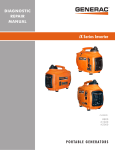
http://biz.lgservice.com
REFRIGERATOR
SERVICE MANUAL
CAUTION
PLEASE READ CAREFULLY THE SAFETY PRECAUTIONS OF THIS BOOK
BEFORE CHECKING OR OPERATING THE REFRIGERATOR .
MODEL:GR-349SQF.CEWQEHU
Color : Euro White
CONTENTS
SAFETY PRECAUTIONS ....................................................................................................................................................... 2
SERVICING PRECAUTIONS.................................................................................................................................................. 3
SPECIFICATIONS................................................................................................................................................................... 4
PARTS IDENTIFICATION ....................................................................................................................................................... 5
REPLACEMENT OF DOOR OPENING TYPE ....................................................................................................................... 6
DISASSEMBLY.................................................................................................................................................................... 7-8
DOOR................................................................................................................................................................................... 7
DOOR SWITCH.................................................................................................................................................................... 7
FAN AND FAN MOTOR........................................................................................................................................................ 7
DEF' CONTROL ASM .......................................................................................................................................................... 8
LAMP.................................................................................................................................................................................... 8
ADJUSTMENT................................................................................................................................................................... 9-10
COMPRESSOR.................................................................................................................................................................... 9
PTC-STARTER..................................................................................................................................................................... 9
OLP (OVER LOAD PROTECTOR) .................................................................................................................................... 10
CIRCUIT DIAGRAM.............................................................................................................................................................. 10
TROUBLESHOOTING..................................................................................................................................................... 11-16
COMPRESSOR AND ELECTRIC COMPONENTS............................................................................................................ 11
PTC AND OLP.................................................................................................................................................................... 12
ANOTHER ELECTRIC COMPONENT............................................................................................................................... 13
SERVICE DIAGNOSIS CHART.......................................................................................................................................... 14
REFRIGERATING CYCLE ............................................................................................................................................ 15-16
MICOM FUNCTION & PCB CIRCUIT EXPLANATION ................................................................................................... 17-33
EXPLODED VIEW .......................................................................................................................................................... 34-35
REPLACEMENT PARTS LIST ............................................................................................................................................ 36-
SAFETY PRECAUTIONS
Please read the following instructions before servicing your
refrigerator.
1. Check the set for electric losses.
7. When standing up after having checked the lower
section of the refrigerator with the upper door open,
move with care to avoid hitting the upper door.
2. Unplug prior to servcing to prevent electric shock.
3. Whenever testing with power on, wear rubber gloves to
prevent electric shock.
8. When tilting the set, remove any materials on the set,
especially the thin plates(ex. Glass shelf or books.)
4. If you use any kind of appliance, check regular current,
voltage and capacity.
9. When servicing the evaporator, wear cotton gloves.
This is to prevent injuries from the sharp evaporator
fins.
5. Don't touch metal products in the freezer with wet
hands. This may cause frostbite.
10. Leave the disassembly of the refrigerating cycle to a
specialized service center. The gas inside the circuit
may pollute the environment.
6. Prevent water from following onto electric elements in
the mechanical parts.
-2-
SERVICING PRECAUTIONS
vacuum operation is over, add the quantity in grams of
R134a to the refrigeration system. Remember that every
system has an exact quantity of R134a with a tolerance of
±5 grams that can be added. (Figure 4)
Air Recharging in Compressor
Test the refrigeration by connecting it electrically before
refilling operation. It is necessary to ascertain the function
of the motor-compressor and identify the defects
immediately. If defects have been found, empty the old
system of possible R134a residue by breaking off the end
of the extension piece at its narrow point. (Figure 1)
Replace the filter and any damaged components. Unsolder
and pull off the piece remaining inside the service tube and
then attach an complete extension with male Hansen and
at last, solder it to the same tube again. (Figure 2)
POINT TO BE
BROKEN
TO THE R134a CYLINDER
CHARGE TUBE
EXTENSION
FEMALE
HANSEN
TO THE REFRIGERATION
SYSTEM
MALE HANSEN
SERVICE TUBE EXTENSION
Figure 4
SOLDERING POINT
Figure 1
Before performing this operation (if the vacuum pump and
refilling cylinder are connected), make sure that the valve
placed between the vacuum pump and the refilling tube are
closed in order to keep the Freon for addition to the system.
(Figure 5)
Figure 2
It is necessary to execute the soldering operation with
valve open so that the fumes caused by oil residue can
come out freely without blowholes between two tubes
during the heating of the point to be soldered.
The extension fitted with the male Hansen is connected to
the female fitting of the vacuum pump tube. (Figure 3)
FILLING OR
CHARGE TUBE
VALVE TO BE OPENED
WHEN REFILLING
TO THE REFRIGERATION
SYSTEM
TO THE VACUUM
PUMP
TO THE CHARGE
CYLINDER
VALVE TO BE CLOSED
AFTER VACUUM
TO THE VACUUM PUMP
PRESSURE
GAUGE
Figure 5
In addition, check the graduated scale on the cylinder for
the quantity of R134a to be added, for example, if we have
750 grams of Freon in the cylinder and must add 165
grams to the group, this amount will be reached when R134a has dropped to 585 grams, remembering that the
indicator shows a lower limit of meniscus. Do this after
choosing the scale corresponding to the gas pressure
different scales reported as the same gas pressure
indicated by the pressure gauge on the top of the column.
To make R134a flow into the system, open the valve
placed at the base of the cylinder and connected to the
filling tube. The amount of Freon cannot be added to the
system all at once because it may cause a blocking of
the motor-compressor. Therefore, proceed by adding the
original quantity of about 20-30 grams and close the valve
immediately.
The pressure rises and the motor compressor must start
sucking the gas and lowering the pressure again.
Regulate the valve again, in the safe way until reaching the
quantity of R134a established for the system being
charged. When the system is running, the suction pressure
must be stabilized between 0.30 to 0.6 atmosphere.
Figure 3
Air evacuating from the system begins as soon as the
pump starts. The refrigeration system must be kept under
vacuum until the reading on the low-pressure gauge
indicates vacuum (0 absolute, -1 atm., -760 mm hg) in any
case it is advisable to keep the pump running for about 30
minutes. (Figure 3)
In case that a considerable leakage occurs it will be
necessary to stop the vaccum pump and to add a small
quantity of Freon to the system, if vacuum should not be
obtained (pressure gauge can't fall to 1 atmosphere), start
the refrigeration unit and find the leakage with the special
leak-finder. When the defective soldering point is visible,
re-do it after opening the extension tube valve and
reestablishing the normal outside pressure inside the
group.
Because the melted alloy is sucked into the tubes and
block them, the pressure must be rebalanced when
vacuum is in the system in soldering. As soon as the
-3-
SPECIFICATIONS
1.Ref. No: GC-389
ITEMS
SPECIFICATIONS
ITEMS
SPECIFICATIONS
DIMENSIONS (mm)
595(W)X626(D)X1880(H)
NET WEIGHT (kg)
74
REFRIGERATOR
Vegetable Container(2 EA)
COOLING SYSTEM
Fan Cooling
COMPARTMENT
Vegetable Container Cover(1 EA)
TEMPERATURE REFRIGERATOR
CONTROL
FREEZER
Transparent Shelf(3 EA)
Knob Dial
Chilled Container(1 EA)*
Button
Dairy Pocket Cover(1 EA)
Full Automatic
DEFROSTING SYSTEM
Egg Tray(2 EA)
DOOR POCKET
Heater Defrost
Little Pocket(5 EA)
DOOR FINISH
Pre-Coated Metal
or Vinyl Coated Metal
Bottle Pocket(1 EA)
OUT CASE
Painted Steel Sheet
FREEZER
Tray Drawer(4 EA)
INNER CASE
ABS
COMPARTMENT
Ice Tray(1 EA)
INSULATION
Polyurethane Foam
COMPRESSOR
PTC Starting Type
DEFROSTING DEVICE
Heater, Sheath
EVAPORATOR
Fin Tube Type
REFRIGERANT
R134a(135g)
CONDENSER
Side & Wire Condenser
LUBRICATION OIL
FREOL @ 22G(210 cc)
* Optional Parts
2.Ref. No: GC-349
ITEMS
SPECIFICATIONS
ITEMS
SPECIFICATIONS
DIMENSIONS (mm)
595(W)X626(D)X1710(H)
NET WEIGHT (kg)
69
REFRIGERATOR
Vegetable Container(2 EA)
COOLING SYSTEM
Fan Cooling
COMPARTMENT
Vegetable Container Cover(1 EA)
TEMPERATURE REFRIGERATOR
CONTROL
FREEZER
Transparent Shelf(2 EA)
Knob Dial
Chilled Container(1 EA)*
Button
Dairy Pocket Cover(1 EA)
Full Automatic
DEFROSTING SYSTEM
Egg Tray(1 EA)
DOOR POCKET
Heater Defrost
Little Pocket(3 EA)
DOOR FINISH
Pre-Coated Metal
or Vinyl Coated Metal
Bottle Pocket(1 EA)
OUT CASE
Painted Steel Sheet
FREEZER
Tray Drawer(4 EA)
INNER CASE
ABS
COMPARTMENT
Ice Tray(1 EA)
INSULATION
Polyurethane Foam
COMPRESSOR
PTC Starting Type
DEFROSTING DEVICE
Heater, Sheath
EVAPORATOR
Fin Tube Type
REFRIGERANT
R134a(135g)
CONDENSER
Side & Wire Condenser
LUBRICATION OIL
FREOL @ 22G(210 cc)
* Optional Parts
-4-
PARTS IDENTIFICATION
Freezer Temperature
Control
Egg Tray(1 or 2)
Removable
Glass Shelf(2 or 3)
Rotatable
Door Basket
(3 or 5)
Lamp
Multi-air Flow Duct
Fresh Meat Keeper
(Optional)
Utility Corner
(movable)
Refrigerator
Temperature Control
Vegetable Drawer
Used to keep fruits
and vegetables, etc.
fresh and crisp.
Bottle Holder
L
2 Bottle
Door Basket
Ice Cube Tray
Freezer
Compartment
Removable
Plinth
Leveling Screw
NOTE : This is a basic model. The shape of refrigerator is subject to change.
-5-
REPLACEMENT OF DOOR OPENING TYPE
2) Separating screw 10 and remove the center hinge 11
and the refrigerator door 12 . Move the position of cap 13 .
Move the position of bracket door 16 and screw 17 .
3) Move the position of upper hinge pin 14 , and cap 15 .
Assemble the refrigerator door 12 . Assemble center
hinge 11 and bolt 10 . Assemble freezer door 21 .
Assemble the lower hinge ➎, bolt ➍ and lower cover ➊.
1. PRECAUTION
1) Before reversing the door, first of all, you should take
out food and accessories like shelves or trays which are
not fixed in the refrigerator.
2) Use Torque Wrench or Spanner to fix or remove the
bolt.
3) Don't lay the refrigerator down in working with it, it will
cause to get out of order.
4) Be careful not to drop the door in disassembling or
assembling the freezer or the refrigerator door.
14
2. HOW TO REVERSE THE DOORS
1) Seperate screw ➋ and remove lower cover ➊ and move
cap lower cover ➌. And, seperate screw ➍, lower hinge
➎, and remove pin ➏. Separating the freezer door 21 in
opening, and more the position the cap ➐.
Move the position of bracket door ➑ and screw ➒.
7
6
5
4
21
15
3
8
9
1
2
12
11
12
10
13
10
11
16
17
21
5
Note: Reversing the doors is not covered by the
warranty.
4
1
-6-
2
DISASSEMBLY
1 DOOR
2 DOOR SWITCH
● Freezer
1) Loosen four screws in upper part and disconnect top
cover.
2) Disconnect Lead Wire from switch.
3) Disengage hook behind the switch by pressing it with
hands.
Door
1) Loosen 2 screws and pull the Lower Cover.
2) Loosen hexagonal bolts fixing the lower hinge to the
body to remove the freezer door only.
Lower Hinge
Bolt
Figure 6
3) Pull out the Door Gasket to remover from the
Door Foam Assy, F.
Figure 9
3 REFRIGERATOR ROOM LAMP
GASKET
1) Remove the Cover Lamp, R by pulling with a 'Ð' type
driver.
2) Remove the Lamp by turning.
Figure 7
Refrigerator Door
1) Loosen hexagonal bolts fixing the center hinge(Hinge,C)
to the body to remove the refrigerator door only.
●
Figure 10
Hinge, C
Bolt
Figure 8
2) Pull out the Door Gasket to remove from the
Door Foam Assy, R.
-7-
4 FAN AND FAN MOTOR
6 DAMPER CONTROL
1) Remove freezer drawers.
2) Remove two cap, screws and loosen two screws in Grille Fan.
3) Pull out the Grille Fan and Shroud, F.
4) Disconnect the housing of lead wire.
5) Separate the Fan Assy.
6) Losse 2 screw fixed to the Bracket.
7) Pull out Shroud, F remove the Fan Motor Assy.
8) Separate the Motor Bracket and Rubber.
1) Remove the Cover Lamp, R and loosen 2 screw.
2) Pull the Control Box, R and separate the lead wire
housing.
3) Remove the Cover Lamp, R.
4) Separate the Insulation Multi Duct and Control Box, R.
5) Disassemble the Knob.
6) Separate the Damper Control and Control Box, R.
7) Separate the Damper Control and Resistor.
8) Disconnect the lead wire.
REFRIGERATOR ROOM LAMP
FAN MOTOR
SHROUD
GUIDE FAN
FAN
GRILLE
Figure 11
Figure 13
5 DEFROST CONTROL ASSY
Defrost Control Assy consists of Thermistor and Fuse, Melting.
Thermistor functions to defrost automatically and it is attached to
metal side of the Evaporator and senses temperature.
Fuse, Melting is a kind of safety device for preventing overheating
of the Heater when defrosting.
At the temperature of 72¡C, it stops the emission of heat from the
Heater.
1) Pull out the Shroud, F after removing the Grille.
2) Separate the connector connected with the Defrost Control
Assy and replace new one.
7 HEATER, SHEATH
In this refrigerator, Heater, Sheath is used for defrosting
heater. During heating, the temperature of heater rises
about 300~500¡C. Therefore, be careful not to burn while
servicing.
1) After removing the Grille and Shroud, separate the
Heater, Sheath by disconnecting the connectors.
2) Exchanged Heater, Sheath and connected the housing.
Fuse, Melting
Thermistor
Heater, Sheath
Figure 12
A
Figure 14
Note: A has been only applied to Voltage 110-127V area.
B has been only applied to Voltage 220-240V area.
A
Fuse, Melting
Thermistor
Heater, Sheath
Figure
12 B - 8 -
Figure 14
B
ADJUSTMENT
3) PTC-Applied Circuit Diagram
to Starting Method for the Motor
1 COMPRESSOR
● According
1) Role
The compressor intakes low temperature and low pressure
gas evaporated from Evaporator of the Refrigerator, and
condenses this gas to high temperature and high pressure
gas, and then plays delivering role to Condenser.
OVERLOAD PROTECTOR(O.L.P)
C
2) Composition
The Compressor is Composed of Compressor Apparatus
compressing gas, Compressor Motor moving Compressor
Apparatus and Case protecting Compressor Apparatus
and Motor. There are PTC-Starter, and Over Load
Protector (OLP) in the Compressor outside. On the other
hand, because the Compressor consists of 1/1000mm processing
precision components and is sealed after production in absence
of dust or humidity, deal and repair with care.
PTC
5
S
3
6
PTC STARTER
COMPRESSOR
MOTOR
M
M
S
HERMETIC
TERMINAL
RSIR
Figure 19
3) Note for Usage
(1) Be careful not to allow over-voltage and over-current.
(2) No Strike
If applying forcible power or strike (dropping or careless
dealing), poor operation and noise may occur.
(3) Use proper electric components appropriate to the
Compressor.
(4) Note to Keep Compressor.
If Compressor gets wet in the rain and rust in the pin of
Hermetic Terminal, the result may be poor operation
and poor contact may cause.
(5) Be careful that dust, humidity, and flux welding don't
inflow in the Compressor inside in replacing the
Compressor. Dust, humidity, and flux due to welding
which inflows to Cylinder may cause lockage and noise.
4) Motor Restarting and PTC Cooling
(1) For restarting after power off during normal
Compressor Motor operation, plug the power cord after
5 min. for pressure balance of Refrigerating Cycle and
PTC cooling.
(2) During normal operation of the Compressor Motor, PTC
elements generate heat continuously. Therefore,
if PTC isn't cooled for a while after the power has been
shut off, Motor can't operate again.
5) Relation of PTC-Starter and OLP
(1) If the power is off during operation of Compressor and
the power is on before the PTC is cooled, (instant shutoff within 2 min. or reconnect a power plug due to
misconnecting), the PTC isn't cooled and a resistance
value grows. As a result, current can't flow to the subcoil and the Motor can't operate and the OLP operates
by flowing over current in only in the main-coil.
(2) While the OLP repeats on and off operation about 3-5
times, PTC is cooled and Compressor Motor performs
normal operation.
If OLP doesn't operate when PTC is not cooled,
Compressor Motor is worn away and causes circuitshort and fire. Therefore, use a properly fixed OLP
without fail.
2 PTC-STARTER
1) Composition of PTC-Starter
(1) PTC (Positive Temperature Coefficient) is a no-contact
semiconductor starting device which uses ceramic
material and this material consists of BaTiO3.
(2) The higher the temperature is, the higher becomes the
resistance value. These features are used as starting
device for the Motor.
6) Note to Use PTC-Starter
(1) Be careful not to allow over-voltage and over-current.
(2) No Strike
Don't apply a forcible power or strike.
(3) Keep apart from any liquid.
If liquid such as oil or water away enter the PTC,
PTC materials it may break due to insulation
breakdown of the material itself.
(4) Don't change PTC at your convenience.
Don't disassemble PTC and mold. If the exterior to the
PTC-starter is damaged, resistance value is altered and
it may cause poor starting of the compressor motor
may cause.
(5) Use a properly fixed PTC.
2) Role of PTC-Starter
(1) PTC is attached to Hermetic Compressor used for
Refrigerator, Show Case and starts Motor.
(2) Compressor for household refrigerator applies to
single-phase induction Motor.
For normal operation of the single-phase induction
motor, in the starting operation flows in both main coil
and sub-coil. After the starting is over, the current in
subcoil is cut off. The proper features of PTC play all
the above roles. So, PTC is used as a motor starting
device.
-9-
3 OLP (OVER LOAD PROTECTOR)
CONTACTING
POINT
1) Definition of OLP
(1) OLP (OVER LOAD PROTECTOR) is attached to the
Hermetic Compressor and protects the Motor by cutting
off current in Compressor Motor in case of over-rising
temperature by Bimetal in the OLP.
(2) When over-voltage flows to Compressor motor, the
Bimetal works by heating the heater inside the OLP,
and the OLP protects Motor by cutting off current which
flows to the Compressor Motor.
COVER
BIMETAL
CONTACTING
POINT
HEATER
TERMINALS
2) Role of the OLP
(1) The OLP is attached to the Hermetic Compressor used
for the Refrigerator and Show Case and prevents the
Motor Coil from being started in the Compressor.
(2) Do not turn the Adjust Screw of the OLP in any way for
normal operation of the OLP.
(Composition and connection Diagram of OLP)
BIMETAL
ADJUST
SCREW
HEATER
Figure 20
CIRCUIT DIAGRAM
2.Ref.
Circuit 1
2.Ref.
Circuit 2
3854JS8003Y
3854JS8003Z
NOTE : 1. This is a basic diagram and specifications vary in different localities.
2.Circuit 2 has been only applied to C4 C5 B3 power cord type.
- 10 -
TROUBLESHOOTING (Mechanical Part)
1 COMPRESSOR AND ELECTRIC COMPONENTS
1
Power
Source.
Remove the PTCStarter from the
Compressor and
measure the voltage
between Terminal C of
Compressor and
Terminals 5 or 6 of PTC.
(Rating Voltage
±10%)?
No Voltage.
OLP disconnected?
YES
2
YES
Replace OLP.
5
Check connection
condition.
Advise the customer
to use a regular
Trans.
Applied voltage isn't
in the range of Rating
Voltage ±10%.
2
3
Check the
resistance of
Motor
Compressor.
Check the resistance
among M-C, S-C and
M-S in Motor
Compressor.
Check the
resistance of
PTC-Starter.
Check the resistance of
two terminals in PTCStarter.
Reconnect.
5
YES
3
NO Replace Compressor.
3
YES
4
5
4
Replace
PTC-Starter.
NO
5
YES
4
5
Check OLP.
Check
starting state.
Check if applying
a regular OLP.
Measure minimum
starting voltage after 5
min. for balancing cycle
pressure and cooling the
PTC.
OLP works within
30 sec. in forcible
OLP operation by
turning instant power
on and off.
Components start in
the voltage of Rating
Voltage ±10% below.
YES
NO
YES
NO
- 11 -
5
Replace OLP.
O.K.
1
2 PTC AND OLP
Normal operation of
Compressor is
impossible or poor.
Observation value is
220V/50Hz : 22§ ±30%
115V/60Hz : 6.8§ ±30%
240V/50Hz : 33§ ±30%
127, 220V/60Hz : 22§
±30%
Separate the PTC-Starter
from Compressor and
measure the resistance
between No. 5 and 6 (only
RSIR type) or No. 4 and 5 of
PTC-Starter with a Tester or
Whistone Bridge.
(Figure 21)
The resistance value is 0
or serveral hundreds § .
The value is ¡˜.
Separate the OLP from the
Compressor and check the
resistance value between
two terminals of OLP with
a Tester. (Figure 22)
YES
Check another
electric components.
NO
Replace OLP.
4
5
6
3
Figure 21
Figure 22
- 12 -
Check another
electric
components.
Replace
PTC-Starter.
3 ANOTHER ELECTRIC COMPONENTS
▼ Cooling is impossible
Compressor
doesn't run.
Running state of
Compressor is poor.
Check if current flows to
the following
components.
Cause.
a. Thermistor
Poor contacting.
b. Starting devices
Shorted or broken.
c. OLP
Poor contacting
or shorted.
d. Compressor coil
Coil shorted.
e. Circuit Parts
Poor contacting
or shorted.
Replace
each component.
Check a starting
voltage.
Low voltage.
Raise the voltage.
Check if current flows
to starting devices.
Poor contacting
and broken.
Replace
each component.
Check current flowing
in sub-coil of
Compressor.
Shorted.
Check capacity of OLP.
Lack of capacity.
The items described
above are normal.
Coil of motor
Compressor.
Check current flowing
in SWITCH, DOOR.
Poor contacting.
Check current flowing in the
MOTOR[MECH], FAN.
Coil is shorted.
Replace
the compressor.
▼ Cooling ability is poor
Fan motor
doesn't run.
Much frost are sticked
to the EVAPORATOR.
Replace
each component.
Check current flowing
of the following
components.
¥ THERMISTOR
¥ FUSE, MELTING
Shorted.
Check current flowing
of the following
components.
¥ HEATER, SHEATH
Replace
each component.
Replace
the Heater, Sheath
- 13 -
4 SERVICE DIAGNOSIS CHART
COMPLAINT
POINTS TO BE CHECKED
Cooling is
impossible.
¥ Is the power cord unplugged from the outlet?
¥ Check if the power switch is set to OFF.
¥ Check if the fuse of power switch is shorted.
¥ Measure the voltage of power outlet.
¥ Plug to the outlet.
¥ Set the switch to ON.
¥ Replace a regular fuse.
¥ If voltage is low, wire newly.
Cooling ability
is poor.
¥ Check if the set is placed close to wall.
¥ Check if the set is placed close to stove, gas
¥ cooker and direct rays.
¥ Is the ambient temperature high or
¥ the room door closed?
¥ Check if put in is hot.
¥ Did you open the door of the set too often
¥ or check if the door is closed up?
¥ Check if the Damper Control is set to "cold-position".
¥ Place the set with the space of about 10cm.
¥ Place the set apart from these heat
¥ appliances.
¥ Make the ambient temperature below.
Foods in the
Refrigerator
are frozen.
¥ Is foods placed in cooling air outlet?
¥ Put in foods after cooled down.
¥ Don't open the door too often and close
¥ it firmly.
¥ Set the control to mid-position.
¥ Check if the control is set to "cold-position".
¥ Is the ambient temperature below 5¡C?
¥ Place foods in high temperature section.
¥ (Front Part)
¥ Set the control to "mid-position".
¥ Set the control to "warm-position".
Dew or ice
forms in the
chamber of
the set.
¥ Is liquid food stored?
¥ Check if put in is hot.
¥ Did you open the door of the set too
¥ often or check if the door is closed up.
¥ Seal up liquid foods with wrap.
¥ Put in foods after cooled down.
¥ Don't open the door too often and close
¥ it firmly.
Dew forms
in the Exterior Case.
¥ Check if ambient temperature and humidity
of surroumcling air are high.
¥ Is there gap in the door packed?
¥ Wipe dew with a dry cloth. This occurrence
¥ is solved naturally in low temperature and humidity.
¥ Fill up the gap.
Abnormal
noise generates.
¥ Are the set positioned in a firm and even place?
¥ Adjust the Adjust Screw, and position
¥ in the firm place.
¥ Remove the objects.
¥ Are any unnecessary objects set
¥ in the back side of the set?
¥ Check if the Tray Drip is not firmly fixed.
¥ Check if the cover of mechanical room
¥ in below and front side is taken out.
To close the door
is not handy.
¥ Check if the door packing is dirty
¥ with filth such as juice.
¥ Is the set positioned in a firm and even place?
¥ Is too much food putted in the set?
Ice and foods
smell unpleasant.
●
REMEDY
¥ Check if the inside of the set is dirty.
¥ Did you keep smelly foods without wrapping?
¥ It smells of plastic.
¥ Fix it firmly on the original position.
¥ Place the cover at the original position.
¥ Clean the door packing.
¥ Position in the firm place and adjust the
¥ Adjust Screw.
¥ Keep foods not to reach the door.
¥ Clean the inside of the set.
¥ Wrap smelly foods.
¥ The new products smells of plastic, but it is
¥ eliminated after 1-2 weeks.
In addition to the items described left, refer to the followings to solve the complaint.
Check if dew forms in
the Freezer.
Defrosting
is poor.
Replace the
Components of
defrosting circuit.
Check Refrigerating
Cycle.
The cycle
is faulty.
Repair the cycle.
Check the
Damper Control
The operation of
the Damper
Control is poor.
Replace the
Damper Control
- 14 -
5 REFRIGERATING CYCLE
▼ Troubleshooting Chart
STATE OF
THE SET
CAUSE
STATE OF THE
EVAPORATOR
TEMPERATURE
OF THE
COMPRESSOR
REMARKS
Freezer room and
Refrigerator
don't cool
normally.
Low flowing sound of
Refrigerant is heard and
frost forms in inlet only
A little high
more than
ambient
temperature.
¥ A little Refrigerant
¥ discharges.
¥ Normal cooling is possible
¥ when injecting of Refrigerant
¥ the regular amount.
WHOLE
LEAKAGE
Freezer room and
Refrigerator
don't cool
normally.
Flowing sound of Refrigerant
is not heard and frost isn't
formed.
Equal to ambient
temperature.
¥ No discharging of Refrigerant.
¥ Normal cooling is possible
¥ when injecting of Refrigerant
¥ the regular amount.
PARTIAL
CLOG
Freeze room and
Refrigerator
don't cool
normally.
Flowing sound of Refrigerant
is heard and frost forms
in inlet only.
A little high
more than
ambient
temperature.
¥ Normal discharging of
¥ refrigerant.
¥ The capillary tube is faulty.
WHOLE
CLOG
Freezer room and
Refrigerator
don't cool.
Flowing sound of Refrigerant
is not heard and frost isn't
formed.
Equal to ambient
temperature.
¥ Normal discharging of
¥ Refrigerant.
MOISTURE
CLOG
Cooling operation
stops periodically.
Flowing sound of Refrigerant
is not heard and frost melts.
Low than
ambient
temperature
¥ Cooling operation restarts
¥ when heating the inlet of
¥ capillary tube.
COMPRESSION
Freezer and
Refrigerator
don't cool.
Low flowing sound of
Refrigerant is heard and
frost forms in inlet only.
A little high
than ambient
temperature.
¥ The pressure of high
¥ pressure part in
¥ compressor is low.
NO COMPRESSION
No compressing
operation.
Flowing sound of Refrigerant
is not heard and no frost.
Equal to ambient
temperature.
¥ No pressure of high pressure
¥ part in the compressor.
LEAKAGE
PARTIAL
LEAKAGE
CLOGGED BY DUST
DEFECTIVE
COMPRESSION
▼ Leakage Detection
● Observe
discharging point of refrigerant which may be in the oil discharging part in the compressor and hole of evaporator.
Whether Compressor
runs or not.
YES
Whether frost
forms or not in
Evaporator.
Frost formed normally
No frost
or forms
in inlet only
Whether oil
leaks or not.
Observe the discharged
amount of Refrigerant.
Normal amount
No or much amount
Moisture Clog.
Faulty
Compressor.
Check Compressor
YES
Inject Refrigerant to Compressor
and check cooling operation.
Clogged by dust.
Gas leakage.
Frost formed normally
- 15 -
(Check the leakage point)
▼ General Control of Refrigerating Cycle
NO.
ITEMS
CONTENTS AND SPECIFICATIONS
WELDING
ROD
(1) H 30
(1) ¥ Chemical Ingredients
(1) ¥ Ag: 30%, Cu: 27%, Zn: 23%, Cd: 20%
(1) ¥ Brazing Temperature: 710~840¡C
(2) Bcup-2
(1) ¥ Chemical Ingredients
(1) ¥ Cu: About 93%
(1) ¥ P: 6.8~7.5%
(1) ¥ The rest: within 0.2%
(1) ¥ Brazing Temperature: 735~840¡C
FLUX
(1) ¥ Ingredients and how to make
(1) ¥¥Borax 30%
(1) ¥¥Borax 35%
(1) ¥ Fluoridation kalium: 35%
(1) ¥ Water: 4%
(1) ¥ Mix the above ingredients and boil until
(1) ¥ they are transformed into liquid.
¥ Make amount for only day.
(1)
¥ Holding period: 1 day
¥ Close the cover of container to prevent dust
¥ putting in the FLUX.
¥ Keep it in a stainless steel container.
DRIER
ASM
(1) Assemble the drier within 30min.
(1) after unpacking.
(2) Keep the unpacked drier at the temperature
of 80~100¡C.
¥ Don't keep the drier in a outdoors because
¥ humidity damages to it.
VACUUM
(1) When measuring with pirant Vacuum
(1 )gauge the charging M/C, vacuum
(1 )degree is within 1 Torr.
(2) If the vacuum degree of the cycle inside is
(2) 10 Torr. below for low pressure and 20 Torr.
(2) for high pressure, it says no vacuum
(2) leakage state.
(3) Vacuum degree of vacuum pump must be
(3) 0.05 Torr. below after 5 min.
(4) Vacuum degree must be same to the
value described item (2) above for more than
20 min.
¥ Apply M/C Vacuum Gauge without fail.
¥ Perform vacuum operation until a proper
¥ vacuum degree is built up.
¥ If a proper vacuum degree isn't built up,¥
¥ check the leakage from
¥ the Cycle Pipe line part and
¥ Quick Coupler Connecting part.
DRY AND
AIR
NITROGEN
GAS
(1) The pressure of dry air must be more
han 12~16kg/cm2
(2) Temperature must be more than
-20~ -70¡C.
(3) Keep the pressure at 12~6kg/cm2 also
(3) when substituting dry air for Nitrogen Gas.
NIPPLE
AND
COUPLER
(1) Check if gas leaks with soapy water.
(2) Replace Quick Coupler in case of leakage.
PIPE
(1)¥ Put all Joint Pipes in a clean box and
(1)¥ cover tightly with the lid so that dust or
(1)¥ humidity is not inserted.
1
2
3
4
5
6
7
- 16 -
REMARKS
¥ Recommend H34 containing 34% Ag in the
¥ Service Center.
¥ Check if gas leaks from joint of the
¥ Coupler.
MICOM FUNCTION & PCB CIRCUIT EXPLANATION
This description is made for GR-349, 389SQ. Please refer to overall PCB circuits for other models.
1 FUNCTION EXPOSITION
1) FUNCTION
(1) The refrigerator starts from optimum condition when electric power is first on. But the operation condition changes "Mid"
➝ "Mid/Max" ➝ "Max" ➝ "Min" ➝ "Min/Mid" ➝ "Mid" whenever pressing the FREEZE TEMP button.
(2) It returns to "Mid" conditions if power off and on again.
VACATION
FREEZE TEMP
QUICK FREEZE
NOTCH
Min
Min/
Mid
Mid
Mid/
Max
Max
TEMP(ûC)
-15
-16.5
-18
-19.5
-22
ROOM
FREEZER
2) QUICK FREEZER
(1) Function to raise the freezing speed by operating the COMP successively. As pressing the QUICK FREEZE button, the
QUICK FREEZE LED is displayed. Then after 3 hours' successive operation of COMP, the QUICK FREEZING function
will be released.
(2) Defrosting During the QUICK FREEZING operates as follow.
When the QUICK FREEZING time is below 90 minutes, defrost and then operate the QUICK FREEZING for the
remaining time. When the QUICK FREEZING time is over 90 minutes, defrost and then operate the QUICK FREEZING
for 2 hours
(3) If QUICK FREEZE button is pressed during defrosting, the QUICK FREEZE LED is lit up. But the QUICK FREEZING
operates for 3 hours after 7 minutes from the end of defrosting.
(4) If VACATION button is pressed during the QUICK FREEZING, the QUICK FREEZING LED function is released.
(5) If power off during the QUICK FREEZING and power on again, the QUICK FREEZING function is released.
3) VACATION FUNCTION
(1) Function for Energy Saving. As pressing the VACATION button, the VACATION LED is displayed and this function is
operated.
(2) Freezer Compartment is not kept by compressor at the notch displayed but at -13¡C± differential.
(3) Defrosting and Fan control is same as normal operation.
(4) If QUICK FREEZE button is pressed during the VACATION FUNCTION, VACATION FUNCTION is released.
(5) If power off during the VACATION FUNCTION and power on again, the VACATION FUNCTION is released.
- 17 -
4) DOOR OPENING ALARM
(1) When the REFRIGERATOR DOOR is opened and won't be closed after 1 minute from the its opened, BUZZER sounds
to notify it.
(2) At frist, BUZZER sounds three times at each intervals of 0.5 second. Then makes a 0.5 second ON/OFF alarm three
times at intervals of 30 seconds.
(3) If the REFRIGERATOR door closed during ALARM, it is released.
FREEZER
DOOR
CLOSE
OPEN
CLOSE
OPEN
CLOSE
three
times
three
times
three
times
BUZZER
within
1 minute
1 minute
30
seconds
30
seconds
5) DISPLAY BUTTON RING
(1) If display function button(FREEZE TEMP, QUICK FREEZE, VACATION) of the front of the TOP COVER is pushed,
BUZZER rings with "DING~ DONG~"(See the BUZZER OPERATION CHECK)
6) DEFROSTING
(1) If the accumulated time for the operation of the COMPRESSOR is meet with 7 hours, the DEFROSTING HEATER is
started.
(2) The first defrosting is performed at 4 hours(compressor ON) later since the power is on.
(3) If DEFROST SENSOR is over 7¡C during DEFROSTING, end the operation of DEFROSTING with DEFROSTING
HEATER paused, And after 7 minutes, the operation for the freezing is started.
But, if DEFROST SENSOR is not reach to 7¡C after 2 hours' operation of the defrosting heater, it represents a defrosting
trouble.(See the TROUBLE REPRESENTING FUNCTION)
(4) If DEFROST SENSOR is short or open, defrosting is not performed.
7) ORDERLY OPERATION OF ELECTRIC PARTS
To avoid NOISE and DAMAGE, the items containing an electric parts such as COMP, DEFROSTING HEATER and FAN
MOTOR operate in order as follows.
OPERATION STATE
WHEN PLUGGED AT FIRST
WHEN DEFROST SENSOR
TEMPERATURE IS OVER
7¡C. (WHEN PURCHASING
OR MOVING)
WHEN DEFROST SENSOR
TEMPERATURE IS BELOW
7¡C. (WHEN POWER
FAILURE OR SERVICING)
OPERATION ORDER
POWER
ON
COMP
ON
after 0.5 sec.
POWER
ON
after 0.5 sec.
DEFROSTING
HEATER ON
after 0.5 sec.
DEFROSTING
HEATER ON
after 10 sec.
COMP
ON
after 0.5 sec.
WHEN RETURNING TO NORMAL
STATE FROM TEST MODE
FAN
ON
FAN
ON
after 0.5 sec.
All Elec. Parts
OFF
COMP
ON
after 7 min .
- 18 -
FAN
ON
after 0.5 sec.
8) SELF-TEST
(1) Function to make service easy in case of occuring a trouble in the product.
(2) When occurring a trouble, if the button is pushed, but the function could not operate.
(3) If a toruble release during the representation of trouble, a refrigerator performs the normal function(RESET).
(4) To represent a ERROR CODE, it use FREEZE TEMP LEDs on TOP COVER. If ERROR occurs, the other LEDs except
ERROR CODE LEDs are all off.
VACATION
FREEZE TEMP
QUICK FREEZE
F1 F2 F3 F4
ERROR CODE LEDs
:ON
O : OPERATE NORMAL
NO.
ITEMS
ERROR CODE LEDs
F1 F2 F3 F4
:OFF
OPERATION IN TROUBLE'S OCCURRING
DESCRIPTION
COMP
FAN
DEFROST HEATER
1
FREEZER
SENSOR abnormal
FREEZER SENSOR open 15 minutes On/
15 minutes Off
or short.
O
O
2
DEFROST
SENSOR abnormal
DEFROST SENSOR open
or short.
O
O
No defrosting
3
DEFROSTING
FUNCTION
is abnormal
DEFROST HEATER,
TEMP. FUSE open or
disconnection (Displayed
after at least 4 hours
from the trouble's
occurring.)
O
O
O
Room Temperature
SENSOR open or short
O
O
O
4
RT-SENSOR
abnormal
NOTE 1)
* NOTE 1) If one second pass after pressing the QUICK FREEZE and FREEZE TEMP buttons togather in normal
operation, operates as follow.
RT-SENSOR
If normal, LEDs on the TOP COVER is all on.
If abnormal, LEDs are all on except VACATION LED.
- 19 -
9) FUNCTION TEST
(1) Function to check the testing function of PCB and refrigerator and to find where the trouble.
(2) The test switch is on the MAIN PCB of refrigerator.
TEST FUNCTION is released and RESET after MAX. 2hours regardless of TEST MODE.
(3) If the buttons on TOP COVER is pushed during TEST MODE, Function is not operated and only BUZZER ring with
"DING~ DONG~"
(4) After the end of TEST MODE, pull out the power cord and plug it in again(RESET).
(5) If a ERROR occurs during the TEST MODE, TEST FUNCTION is released and DISPLAY LEDs represent ERROR
CODE.
(6) If the TEST swithch is pushed during ERROR CODE, TEST FUNCTION is not operated.
MODE
OPERATION
CONTENTS
REMARKS
TEST 1
Press TEST button
once.
1. COMP OPERATES SUCCESSIVELY.
2. FAN OPERATES SUCCESSIVELY.
3. DEFROSTING HEATER OFF
4. ALL DISPLAY LEDS ON.
TEST 2
Press TEST button
once in the state of
TEST MODE 1.
1. COMP OFF.
2. FAN OFF.
3. DEFROST HEATER ON.
4. ALL THE DISPLAY LEDS OFF EXCEPT
QUICK FREEZE AND VACATION LEDS.
If DEFROST HEATER
is over 7¡C, it returns
to the NORMAL STATE.
NORMAL
STATE
Press TEST button
once in the state of
TEST MODE 2.
Return to the initial condition.
(RESET)
Comp starts
after 7 minutes.
¥ LED Check Function : Press the QUICK FREEZE and FREEZE TEMP buttons at the same time. After 1 sec., all the
LEDs of the DISPLAY are ON simultaneously. If release the BUTTON, return to the previous
condition.
- 20 -
2 FUNCTION DESCRIPTION
1) ELECTRIC CIRCUITS
TRANS secondary side is composed of electric power circuits for RELAY driving electricity (12Vdc) and for supplying
electricity to MICOM and IC (5Vdc). The voltage in each part is as follows.
PARTS
both ends of VA1
both ends of CM1
both ends of CM2
both ends of CE2
both ends of CC2
VOLTAGE
230Vac
14Vac
17Vdc
12Vdc
5Vdc
VA1 is the part to protect over voltage and noise. When more than 385V is applied, the thermal-fuse(130°C cut-off, local
option) in a first part of TRANS is cut so that the elements in the secondary side of TRANS are protected.
2) OSCILLATION CIRCUIT
CIRCUIT for occurring CLOCK which motivates the internal local element of IC1 to transmit and receive an information and
BASIC TIME for calculating time. Use a proper form for OSC 1. Because in case that SPECIFICATION is changed, the
calculated time in IC1 is changed or IC1 isn't able to operate.
3) RESET CIRCUIT
All the internal parts of MICOM(IC1) return to the initial condition when the early power ON or apply power again in MICOM
after temporary power failure. As a result, all the functions operate according to the early condition. At the early period of
power ON the "LOW" voltage is applied in the RESET terminal of MICOM for the fixed time. The RESET terminal is 5V
during the general operation.
- 21 -
4) LOAD/BUZZER OPERATION, DOOR OPENING SENSING CIRCUIT
(1) LOAD OPERATION CHECK
KIND OF LOAD
MEASURING POINT (IC4)
STATE
COMP,
COMP COOLING FAN
No.11
FAN MOTOR
DEFROSTING HEATER
No.12
No.13
ON
below 1V
OFF
12V
• If the DOOR-R is opened during FAN MOTOR is operated, FAN MOTOR is stopped immediately.
• The A , B of DOOR S/W-R is connected DOOR OPEN DETECTION CIRCUIT as follow.
• If the DOOR-R is opened or closed, then the DOOR S/W-R is ON/OFF, and the LAMP-R is ON/OFF,
and at the same time, S/W of the A , B of DOOR S/W-R for detection of DOOR-R open is ON/OFF.
(2) DOOR OPENING PERCEPTION CHECK
*NOTICE: If you would change DOOR S/W-R, must use the componenot of right PART NUMBER. Because there is a similar
type DOOR S/W-R of NOT MICOM MODEL, it's logic of the A , B of DOOR S/W-R is reversed.
MEASURING POINT
NO.13 OF IC 1 (MICOM)
REFRIGERATOR DOOR
CLOSE
5V(S/W of A , B is OFF state)
OPEN
0V(S/W of A , B is ON state)
• Even though LAMP-R is operated a normal ON/OFF according to DOOR S/W-R, but the MICOM couldn't detect a
DOOR-R opened or closed of lead wire of the A , B is abnormal or S/W of the A , B of DOOR S/W-R is abnormal.
• When DOOR-R open isn't detected : Even though DOOR-R is opened, FAN MOTOR couldn't stop.
When DOOR-R close isn't detected : Even though DOOR-R is closed, BUZZER sounds a DOOR OPEN ALARM.
check a lead wire of the A , B and DOOR S/W-R.
- 22 -
(3)BUZZER OPERATION CHECK
CONDITIONS
DISPLAY FUNCTION BUTTON RING
(DING~ DONG~)
MEASURING
POINT
0.05s
IC1 (No.14 Pin)
IC1 (No.13 Pin)
0.2s
0.1s
DOOR OPEN ALARM
(SCREECHING)
1s
0.5s
5V
5V
0V
0V
5V
5V
0V
0.5s
ov
ov
0V
2.66khz (DING~)
2.232khz (DONG~)
- 23 -
OFF
3.1khz
OFF
5) TEMP SENSOR CIRCUITS
(RTÐ SENSOR)
(DEFROST SENSOR)
(FREEZER COMPARTMENT
SENSOR)
The above circuit reads the surrounding temperature, DEFROSTING temperature and FREEZER ROOM temperature into
MICOM(IC1). OPEN or SHORT state of each SENSOR is as follows.
SENSOR
CHECK POINT
ROOM TEMPERATURE
SENSOR
POINT A Voltage
DEFROST SENSOR
POINT B Voltage
FREEZER SENSOR
POINT C Voltage
NORMAL (-30¡C~50¡C)
SHORT
OPEN
0.5V ~ 4.5V
0V
5V
6) SWITCH INPUT CIRCUIT
The following circuit is a test switch input circuit for checking the refrigerator.
- 24 -
7) TEMPERATURE COMPENSATION
FREEZER TEMPERATURE
COMPENSATION
FREEZER ROOM
RESISTANCE VALUES(R1)
TEMPERATURE COMPENSATION
REMARKS
180 k½
+ 5.0¡C
COMPENSATE WARMLY
56 k½
+4.0¡C
33 k½
+3.0¡C
18 k½
+2.0¡C
12 k½
+1.0¡C
10 k½
0¡C
8.2 k½
-1.0¡C
5.6 k½
-2.0¡C
3.3 k½
-3.0¡C
2 k½
-4.0¡C
470 ½
-5.0¡C
STANDARD
COMPENSATE COOLLY
¥ TEMPERATURE COMPENSATION TABLE by adjusting resistance values. (the temp difference compared to the present
temp.)
eg) If the compensation resistance of freezer compartment is changed from 10K (present resistance) to 18K (revised
resistance), the temp of freezer compartment goes up by +2¡C.
- 25 -
¥ TEMPERATURE COMPENSATION OF FREEZER ROOM
Revised resistance
470½
2k½
3.3k½
5.6k½
8.2k½
10k½
12k½
18k½
33k½
56k½
180k½
NOT
COMPENSATE
1¡C↑
2¡C↑
3¡C↑
4¡C↑
5¡C↑
6¡C↑
7¡C↑
8¡C↑
9¡C↑
10¡C↑
1¡C↓
NOT
COMPENSATE
1¡C↑
2¡C↑
3¡C↑
4¡C↑
5¡C↑
6¡C↑
7¡C↑
8¡C↑
9¡C↑
2¡C↓
1¡C↓
NOT
COMPENSATE
1¡C↑
2¡C↑
3¡C↑
4¡C↑
5¡C↑
6¡C↑
7¡C↑
8¡C↑
3¡C↓
2¡C↓
1¡C↓
NOT
COMPENSATE
1¡C↑
2¡C↑
3¡C↑
4¡C↑
5¡C↑
6¡C↑
7¡C↑
4¡C↓
3¡C↓
2¡C↓
1¡C↓
NOT
1¡C↑
COMPENSATE
2¡C↑
3¡C↑
4¡C↑
5¡C↑
6¡C↑
5¡C↓
4¡C↓
3¡C↓
2¡C↓
1¡C↓
NOT
COMPENSATE
1¡C↑
2¡C↑
3¡C↑
4¡C↑
5¡C↑
6¡C↓
5¡C↓
4¡C↓
3¡C↓
2¡C↓
1¡C↓
NOT
COMPENSATE
1¡C↑
2¡C↑
3¡C↑
4¡C↑
7¡C↓
6¡C↓
5¡C↓
4¡C↓
3¡C↓
2¡C↓
1¡C↓
NOT
COMPENSATE
1¡C↑
2¡C↑
3¡C↑
8¡C↓
7¡C↓
6¡C↓
5¡C↓
4¡C↓
3¡C↓
2¡C↓
1¡C↓
NOT
COMPENSATE
1¡C↑
2¡C↑
9¡C↓
8¡C↓
7¡C↓
6¡C↓
5¡C↓
4¡C↓
3¡C↓
2¡C↓
1¡C↓
NOT
COMPENSATE
1¡C↑
10C↓
9¡C↓
8¡C↓
7¡C↓
6¡C↓
5¡C↓
4¡C↓
3¡C↓
2¡C↓
1¡C↓
NOT
COMPENSATE
Present resistance
470½
2k½
3.3k½
5.6k½
8.2k½
FREEZER
ROOM
10k½
(R1)
12k½
18k½
33k½
56k½
180k½
¥ This circuit is aimed to input the necessary temperature compensation values into the MICOM in order to adjust the freezer
temperature which is different in each model.
- 26 -
8) LIGHTING CIRCUITS OF KEY BUTTON INPUT AND DISPLAY PARTS
FREEZER TEMP
CONTROL KEY
DISPLAY PART
The above circuit is to judge the operation conditions of function key and to light each function indicating LED. It is operated
by SCAN method.
- 27 -
3. SENSOR RESISTANCE CHARACTERISTICS TABLE
MEASURED TEMPERATURE
RESISTANCE OF FREEZER SENSOR
RESISTANCE OF DEFROST SENSOR, ROOM TEMPERATURE SENSOR
-20¡C
22.3k½
77k½
-15¡C
16.9k½
60k½
-10¡C
13.0k½
47.3k½
-5¡C
10.1k½
38.4k½
0¡C
7.8k½
30k½
+5¡C
6.2k½
24.1k½
+10¡C
4.9k½
19.5k½
+15¡C
3.9k½
15.9k½
+20¡C
3.1k½
13k½
+25¡C
2.5k½
11k½
+30¡C
2.0k½
8.9k½
+40¡C
1.4k½
6.2k½
+50¡C
0.8k½
4.3k½
¥ The tolerance of sensor resistance is ±5%.
¥ Be sure to measure the sensor resistance after keeping the sensor more than 3 minutes at a measuring temperature.
(It needs delay due to sensor speed.)
¥ Measure the resistances of SENSORs with a digital tester after disconnecting CON 4 of MAIN PWB ASSY.
- 28 -
4. MAIN PWB ASS'Y AND PARTS LIST
1) MAIN PWB ASS'Y
D5
CE3
6871JB1037
+
CM2
D1 D3 D4 D2
+
CE4
IC3
+
CC1
CE2
+
+
CE6
J06
+
J07
CE5
Q4
CE1
IC2
CM1
STICKER
CC2
OP2
J01
J12
Q1
J08
R21
TRANS
R20
J13
CC3
OP1
Q2
IC1
J14
Q3
CC4
BUZZER
R4 R18 R3
D7
R6
J15
R14
J09
CC10
CC6
R19
RY1
RY2
IC4
D8
J05
RY3
J10
J11
OSC1
RF3
J02 R7 J04
R1
R8
CC5
R10
R9
IC6
CC9
CC8
CC7
98 12
R16
R13
R15
R17
R12
TEST
R11
RF2
COMP
F-FAN
D-HEATER
RF1 RT-SENSOR
1 9
6
VA1
CON1
CON3
D
R-DOOR
- 29 -
F
1
CON2
DIP
D6
2) REPLACEMENT PARTS LIST
- 30 -
3) PWB ASS'Y, DISPLAY AND PARTS LIST
- 31 -
5. PWB circuit drawing- The PWB circuit drawing may change without notice.
? ?? ?
- 33 -
EXPLODED VIEW & REPLACEMENT PARTS LIST
102A
103B
114A
103A
503B
281B
102B
120H
109C
281F
120E
406B
120B
501A
120D
120C
120A
405C
304A
404A
282B
604F
409B
401A
405A
329A
301A
330B
610E
332A
109A
105A
108A
411A
407A
283B
318A
106B
308A
307A
104C
314A
309A
329C
420A
327A
328A
104C
104A
310A
317A
303D
106B
109B
104A
323B
315C
315B
103C
312A
319B
319A
319C
315A
315C
315B
- 34 -
230A
233A
231A
235A
136E
241A
249B
241A
249C
136F
145C
140A
249A
237A
155A
210A
241C
151A
200A
151B
125A
203A
136Y
201A
136A
281D
136B
136C
136D
210A
- 35 -