1
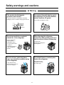
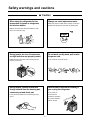
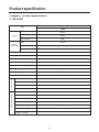
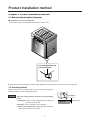
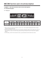
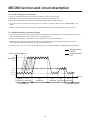
http://biz.lgservice.com
KIMCHI REFRIGERATOR
SERVICE MANUAL
CAUTION
PLEASE READ CAREFULLY THE SAFETY PRECAUTIONS OF THIS MANUAL
BEFORE CHECKING OR OPERATING THE REFRIGERATOR.
MODEL : GR-K192AF
Safety regulations
1. First check if there is any electric leakage in the refrigerator unit.
2. Always unplug the refrigerator before handling any electricity conducting parts.
3. When testing the refrigerator with the power on, use insulated gloves for safety.
4. When using measuring instruments, check the rated current, voltage and capacity.
5. Do not allow water or moisture to get into the mechanical or electrical parts of the refrigerator.
6. Remove all things on top of the refrigerator before tilting it during repairs to avoid spills.
Be especially careful for thin objects (glass sheet, book).
7. When the refrigerating cycle is damaged, always request service to the major repair service agency.
(This is to prevent the house from getting dirty from the gas within the cycle.)
8. Always double check for repairs related to safety to ensure customer safety.
Contents
1. Safety warnings and cautions .......................................................................................................................3
2. Product specification .....................................................................................................................................6
3. Product installation method ..........................................................................................................................7
4. Circuit diagram ...............................................................................................................................................8
5. MICOM function and circuit description.......................................................................................................9
6. Freezing cycle and refrigerant.....................................................................................................................31
7. General details about the product ..............................................................................................................33
8. Major repair method for freezing cycle.......................................................................................................35
9. Characteristics of each part ........................................................................................................................44
10. Cautions for disassembling the product ..................................................................................................52
11. Assembly diagram and service parts list .................................................................................................53
-2-
Safety warnings and cautions
Chapter 1. Safety warnings and cautions
u Always observe the ‘Safety Warnings’ and ‘Cautions’, which hare intended to ensure safety while repairing or operating
the product.
u Precautions are classified into ‘Warning’ and ‘Caution’, as explained below.
w Warning Warning means a dangerous condition which could result in significant damage, injury or death if
the instructions are not followed.
w Caution
Caution means a condition which could result in damage or injury if instructions are not followed.
w Warning
Use caution to prevent electric shock
Do not allow the consumer to repair,
disassemble or modify the refrigerator.
The control panel (main
PCB) uses 310V. When
replacing PCB parts, wait at
least 3 minutes after
unplugging. Always unplug
the refrigerator before
repairing.
Damaged power plug can
cause fire or electric
shock.
Make sure that the power plug is not
pressed by the back of the refrigerator
Use a dedicated circuit.
Overloading circuits or outlets
could cause a fire.
Power plug may be
damaged and cause a fire
or electric shock.
-3-
Safety warnings and cautions
w Warning
This product should always be
grounded, when needed.
Do not store flammable liquid or gas in
the refrigerator such as ether, benzene,
alcohol, medicine, LP gas etc.
If you think that there is a possibility of electricity
leakage by water or moisture, always ground the unit.
It can cause an explosion or a fire.
Grounding screw
Grounding line
Copper plate
Ether
More than 7
Do not store medicine or academic
material etc. in the refrigerator.
Ben
zene
LP
gas
When disposing the refrigerator,
remove the rubber packing on the door
and do not leave it where children play.
Store an object that
requires precise
temperature control
can cause deterioration
in quality or
unexpected reaction to
cause a dangerous
situation.
A child can be
dangerously entrapped in
the refrigerator.
Do not set items, particularly flower
vase, cup, cosmetic or medicine on top
of the refrigerator.
Do not stack items or carelessly store
food on the refrigerator.
Items stored on the
refrigerator could fall
and cause injury.
It can cause fire and
electric shock or cause an
injury from dropping.
-4-
Safety warnings and cautions
w Caution
When using the refrigerator for low
temperature in freezer or refrigerator,
do not store bottles.
Always use exact replacement parts.
Make sure that the model name, voltage, current and
temperature ratings are correct for the electric part.
Bottles can freeze and cause the bottles to crack,
which can cause an injury.
During repairs, be sure all connectors
are tight and wires are properly routed.
Do not bend, modify, bend, pull or twist
the power cord.
Make sure the connectors of the housing part are
properly connected.
It can cause fire or electric shock.
During repairs, remove all dust and
foreign material from the housing part,
connector part and check part.
Allow at least 5 minutes for resetting if
you unplug the refrigerator.
If can cause an
overload to the
condenser operation
and cause problems.
It can prevent problems such as tracking or short
circuit.
After 5 minutes
-5-
Product specification
Chapter 2. Product specification
2-1. GR-K192AF
GR-K192AF
Item
SPEC
Volume
External
dimensions
Usable volume
188.8Li
Left compartment
94.3Li
Right compartment
94.3Li
Width
922mm
Depth
699mm
Height
883mm
Total weight
66kg
Motor power consumption
115W
Direct cooling
Cooling method
Electronic
Store/Season
CYCLO PENTANE
Insulation material
1 pc.
Fresh vegetable basket
6 pcs. (6 large)
Kimchi refrigerator container
2 pcs.
Low temperature catalytic deodorizing system
Freeze cycle
Compressor
NR58LBQH
Evaporator
PIPE ON SHEET
R134a(145g)
Refrigerant (amount)
FREOL@15G(210cc)
Oil
Electrical part rating
PTC
P6R8MB
OLP
4TM412TFBYY
ø110,3 blades attached
Fan motor for compressor cooling
Left compartment seasoning heater
115V / 80W(Resistance:605Ω)
Right compartment seasoning heater
115V / 80W(Resistance:605Ω)
Capacitor (running)
250VAC 10µF
Capacitor (starting)
200VAC 50µF
-6-
Product installation method
Chapter 3. Product installation method
3-1. Method to adjust height of refrigerator
■ First adjust the level of the refrigerator.
(If the floor is uneven, the refrigerator may vibrate or cause noise.)
Horizontal adjustment leg
(lower handle part)
u Adjust the front to be leveled by turning the height adjustment screws under the front corners in the arrow direction.
3-2. Grounding method
Plug the cord into a 115V grounded outlet. If you are unsure of the voltage or
grounding integrity, consult a qualified electrician.
Caution
Grounding line
Take care not to ground the circuit at one of the following
places:
1. Water pipe: If there is a plastic piping within the system, the
ground may not be valid.
2. Gas pipe: There is a danger of fire or explosion.
3. Phone line or lightning rod: If lightning strikes, dangerous
voltage may be induced in the circuit.
-7-
Copper plate
More than 75cm
Circuit diagram
Chapter 4. Circuit diagram
-8-
MICOM function and circuit description
Chapter 5. MICOM function and circuit description
5-1. Function description
5-1-1. Display part
Kimchi srore
Notch
Temperature
Vegetable/Fruit
Light freezing
Freezing food
Min
Mid
Max
Min
Mid
Max
Min
Mid
Max
Min
Mid
Max
0°C
-1.0°C
-2.0°C
3.5°C
2.5°C
1.5°C
-4.0°C
-5.0°C
-6.0°C
-5°C
-18°C
-21°C
1. When the power is connected for the first time, it is set to “Lock”, “Left compartment-Cabbage Kimchi-Mid” and “Right
compartment-Cabbage Kimchi-Mid”.
2. During a power shut-down or when the power is reconnected, the refrigerator maintains the prior display. But in case of a
power-shut down or power reconnection during rhythm fermenting, the temperature returns to “Mid” for the applicable
food type.
3. In “Lock” status, you will not hear a buzzer even when you press the buttons and the functions will not work.
-9-
MICOM function and circuit description
5-1-2. Food storage/seasoning function
(1) When selecting food type and storing temperature
1. Press the “Lock/Unlock” button for more than 2 seconds to switch to “Unlock” status.
2. Press the “Kimchi store” button to select “Mid” ’ “Max” ’ “Min” ’ “Mid”, “Vegetable / Fruit” button “Mid” ’ “Max” ’ “Min”
’ “Mid”, and “Feezing” button “Normal” ’ “Max” ’ “Ligth Freeaing” ’ “Normal” in sequence
3. Press the “Lock/Unlock” button to complete the selection of food type and storing temperature. At this time, if a minute
passes without pressing the “Lock/Unlock” button, it will automatically switch to Lock status and end the food type and
storing temperature selection mode.
(2) When selecting rhythm fermenting (seasoning)
1. Press the “Lock/Unlock” button for more than 2 seconds to switch to “Unlock” status.
2. At this condition, press “Fermentation” button to select “Normal
” ’ ”Normal ” ’ ”More
” ’ ”Underground
Fermentation ” ’ ”Less ” ’ ” Less ” ’ ” Normal
” in sequence, and when the fermentation type is changed
from “Less” to “Normal”, the food type is selected by the order of “Cabbage kimchi” ’ ”Radish kimchi” ’ ”Broth kimchi”
in sequence. However, “Underground Fermentation ” is only for “Cabbage kimchi.”
3. Press the “Lock/Unlock” button to complete the rhythm fermenting (seasoning). At this time, if a minute passes without
pressing the “Lock/Unlock” button, it will automatically switch to Lock status and end the rhythm ferment (seasoning)
selection mode.
4. When “Rhythmic fermentation” is terminated, the remaining time is displayed, and when the fermentation is completed, “0
hour” is displayed as the remaining time and the storing temperature is automatically set to “Mid
(3) When selecting flavor keeping
1. Press the “Lock/Unlock” button for more than 2 seconds to switch to “Unlock” status.
2. Select “Kimchi store” as storing type. (Flavor keeping function is only limited to “Kimchi store”)
3. At this time, press the “Flavor keeping” button to select or cancel the flavor keeping function.
4. Press the “Lock/Unlock” button to end the flavor keeping selection mode. At this time, if a minute passes without pressing
the “Lock/Unlock” button, it will automatically switch to Lock status and end the flavor keeping selection mode.
5. If you select flavor keeping during seasoning process, it will immediately end the seasoning and switch to flavor keeping.
At this time the storing temperature will automatically be set to “Mid”.
6. If you select the flavor keeping function, the refrigerator will lower the temperature to maintain the current Kimchi flavor.
(-1 degrees for “Min”, -0.5 degrees for “Mid” and -0 degrees for “Max”.)
7. During flavor keeping operation, a cold shock operation is done every 12 hours.
8. If you select rhythm fermenting during flavor keeping, the flavor keeping function will be canceled.
- 10 -
MICOM function and circuit description
5-1-3. When selecting power on/off function
1. Press the "Lock/Unlock" button for more than 2 seconds to switch to "Unlock" status.
2. At this time, press the "Power" button for more than 2 seconds to turn the power off.
3. At this time, all the LEDs in the display will be turned off with the power off LED turning on.
4. If you press the "Power" button when the power is off, it will turn on the power and recover to "Cabbage Kimchi" and
"Mid".
5. When the power is turned off, the heater of the applicable compartment is turned off and the valve will be closed.
5-1-4. Rhythm fermenting control pattern diagram
1. The fermenting control pattern varies, depending on the temperature of the Kimchi when it is placed into the storage, the
type of Kimchi being made and the degree of the seasoning selected.
2. In the 1st seasoning cycle, if the Kimchi is at room temperature, the cold control operates.
3. During the seasoning cycle, if the Kimchi is cold, the seasoning heater is turned on and if the Kimchi is warm, the
seasoning heater is turned off.(Only 1st seasoning and 2nd seasoning)
4. If a failure occurs, such as a sensor error during seasoning, the storage will default to Cabbage Kimchi storage status.
: Seasoning heater
ON/OFF
: Seasoning heater
OFF
5℃
1.0 ℃
-0.5 ℃
-2.0 ℃
the Kim
place
chi
d
is at r in the refrig
oom te
e
mpera rator
ture
18 ℃
(Broth Kimchi:
10 ℃)
When
t
the re he Kimchi
p
friger
ator is laced in
c
ool
When
Kimchi sensor temperature
Time
Storage
operation
1st
seasoning
2nd
seasoning
3rd
seasoning
Seasoning start
4th
5th
seasoning seasoning
Seasoning complete
- 11 -
MICOM function and circuit description
5-1-5. Temperature control method
1. The compressor runs or stops and the 3-way valve opens or closes depending on the temperature sensed in the left and
right compartment.
2. If the temperature in either compartment is unsatisfactory, the compressor is turned on and the 3-way value is opened to
the affected compartment.
3. If the temperature in both compartments is unsatisfactory, the compressor is turned on and runs until both compartments
become satisfactory. The 3-way valve is opened and closed to each compartment alternatively until the temperature is
satisfactory.
4. During the seasoning cycle, if the temperature is low, the heater is turned on and if the temperature is high, the
compressor is turned on and the 3-way value is opened.
Left compartment temperature
Right compartment temperature
3-Way valve position
COMP
Satisfactory
Satisfactory
Note 1) g
OFF
Satisfactory
Unsatisfactory
Right compartment
ON
Unsatisfactory
Satisfactory
Left compartment
ON
Unsatisfactory
Unsatisfactory
Left 20 min/Right 20 min
ON
Note1) When the temperature is satisfactory in both compartments, the 3-way valve is open to whichever compartment that
has had a satisfactory temperature most recently.
■ Summary chart of COMP and 3-Way valve operation
Left
compartment
sensor
Temperature
unsatisfactory
Right
compartment
sensor
Temperature
satisfactory
Left
compartment
3-way valve
OPEN
CLOSE
Right
compartment
3-way valve
OPEN
CLOSE
ON
COMP
OFF
5-1-6. Buzzer sound
When you press a button on the front display, you will hear a varying buzzer sound depending on the type and function.
(Refer to Buzzer operating circuit in p21).
5-1-7 Power failure compensation function
1. When the power is restored after an outage, the refrigerator performs the setting originally programmed except for Error
status and Test mode.
2. If the power fails during the seasoning process, there is not power outage compensation function and the storage defaults
to previously set Kimchi type and temperature of "Mid". (to protect excessive seasoning)
- 12 -
MICOM function and circuit description
5-1-8. Operation in response to ambient temperature
The storage senses the ambient temperature and adjusts the temperature in the compartments accordingly. This keeps the
storage from being too cold or too warm because of seasonal variations and maintains exact temperatures in the
compartments.
In general operation
Storage temperature
of the left and right
compartments
Operation in response to the ambient temperature
Season
Spring
Summer
Autumn
Winter
5-1-9. Sequential operation of components
Components (compressor, 3-way valve and left/right seasoning heater) are operated in a specific order to prevent damage
and noise caused by simultaneous operation of all parts when the unit is started and after completing the self-test routine.
Operation status
Operating order
Immediately
Temperature of
the left of right
sensor is >45°C
Power
on
3 min
10 sec
3-way
valve
left
open
3-way
valve
open
Initial power-up
Immediately 0.5 sec
Temperature of
the left of right
sensor is <45°C
Power
on
Left
seasoning
heater
on
Remarks
Compre
ssor on
5 sec
Right
seasoning
heater
on
3 sec
0.5 sec
Left
seasoning
heater
off
3 min
10 sec
7 min
Compressor
on
loads
When returning to
normal status in test
mode
off
3 sec
Compressor
on
3-way
valve
left open
3-way
valve
open
All
Right
seasoning
heater
off
3 min
3-way
valve
open
3-way
valve
left open
g Operation order may slightly vary depending on temperature setting.
- 13 -
The 3-way valve is
opened to both
compartments for 3
minutes; then it is
opened to either
the left or the right
compartment,
depending on the
temperature in the
compartments.
MICOM function and circuit description
5-1-10. Error diagnosis function
1. The error diagnosis function is the function to support SVC in case of an error that can affect the performance of the product.
2. If an error occurs, the control panel button will not work.
3. If an error occurs and is resolved, the refrigerator will default to the normal status. (The unit is reset.)
4. The error codes are shown in segment for the remaining seasoning time display of the right compartment, and all LEDs,
except for failure code, are turned off.
NO
Item
Error code display
Error contents
1
Failure of left
compartment
sensor (R1).
Displays "E1" on the seasoning remaining
time part
Left compartment lid sensor disconnected or short circuited
2
Failure of right
compartment
sensor (R2).
Displays "E2" on the seasoning remaining
time part
Left compartment lid sensor disconnected or short circuited
3
Failure of ambient
temperature
sensor (RTS)
4
Communications
error
In case of an ambient temperature sensor error, the error code is not displayed and press the left and right
compartment "Store" buttons for more than 1 second when checking the LED.
When communication is not working continuously for 30 sec
Only LED for "E1" and "E2" was on
Note 1) The failure code is not displayed for the outside temperature sensor failure, but for ‘LED CHECK’ (by pressing and holding “Kimchi
store” button on the left chamber and “Kimchi store” button on the right chamber together for one second or longer). If the outside
temperature sensor is normal, all LEDs are turned ON, but if abnormal, all LEDs are turned ON with the remaining time display on
the right chamber OFF.
- 14 -
MICOM function and circuit description
5-1-11. Test function
1. The test function checks the functions of the PCB and the refrigerator, searching for errors in parts.
2. The test switch on the PCB operates the test mode. The refrigerator reverts to the normal mode after 2 hours if you forget
to end it manually.
3. When the test mode is active, the buttons on the control panel are disabled but the buzzer still sounds a ding if one is pressed.
4. When the test mode is completed, unplug the refrigerator briefly and plug it in again to reset it and allow normal
operation.
5. If a sensor failure or other failure is detected during the test mode, release the test mode to display the failure code.
6. During the display of the error code, test mode does not work even if you press the Test switch.
Mode
Operation
COMP fan motor
VALVE
Left and Right
DIAPLAY LED
Remarks
seasoning heater
TEST1
Press the test
switch once
ON
Left compartment
20minute / Right
compartment 20
minute
OFF
Error code
display “11”
This test checks
the refrigeration
system for the left
and right
compartments.
TEST2
Press the test
switch once when
Test 1 indicates it
is completed.
ON
Right
compartment
valve OPEN
OFF
Error code
display “22”
This test checks
the refrigeration
system for the right
compartment only.
TEST3
Press the test
switch once when
Test 2 indicates it
is completed.
ON
Left compartment
valve OPEN
OFF
Error code
display “33”
This test checks
the refrigeration
system for the left
compartment only.
TEST4
Press the test
switch once when
Test 3 indicates it
is completed.
OFF
ON
Error code
display “44”
This test checks
the seasoning
heaters.
Normal Press the test
recovery switch once when
Test 4 indicates it
is completed.
After a maximum of 30 minutes or when the temperature of the compartments is higher
than 40C , the storage will default to its initial status.
The compressor operates after a delay of 7 minutes.
LED CHECK function
All LEDs are turned ON by pressing and holding “Kimchi store” button on the left chamber and “Kimchi store” button on the
right chamber together for one second or longer. When these buttons are released, the LED returns to the previous state.
- 15 -
MICOM function and circuit description
5-2. Circuit description
5-2-1. Power circuit
The power circuit consists of the noise attenuation part and the SMPS (Switch Mode Power Supply) part. The SMPS
consists of the rectifier (BD1 & CE1) to convert AC voltage to DC voltage, switching part (IC3) to switch the converted DC
voltage, transformer to transmit energy of the first side of the switching end to the second side, the secondary power to
supply power to MICOM and IC, and the feedback part (IC4) to feedback the secondary voltage to the first side of the
transformer in order to maintain the secondary voltage constant.
Caution
: High voltage (DC 310V) is maintained in this circuit. Wait at least 3 minutes after unplugging to allow the
current to dissipate. There is a danger of electric shock.
5-2-2. Oscillation circuit
The oscillation circuit provides the clock signal for
synchronization and calculation of time in relation
to the logic elements of microprocessor IC1
(MICOM). OSC1 must always use the original
rated parts, because if the specification changes,
the timing generated will not be correct, causing
erratic functioning of the microprocessor.
5-2-3. Reset circuit
The reset circuit allows the entire process to be
started from the initial status by resetting the
various elements within the MICOM (IC1), such as
RAM, whenever power is applied to the unit. Low
voltage is applied to the reset terminal for 10ms at
the beginning of the power input. The reset
terminal has a voltage of 5 V during general
operation. (If the reset operation fails, the
microprocessor will not operate.)
- 16 -
MICOM function and circuit description
5-2-4. Load/Buzzer driving circuit
(1) Load driving circuit
Type of load
COMP. fan motor
Left seasoning heater
Right seasoning heater
Measuring point (IC7)
13
10
11
Status
ON
Within 1V
OFF
12V
(2) Buzzer driving circuit (located on display PCB)
g Only the buzzer sound for the Lock/Unlock operation is shown in this SVC technical manual.
LED MODULE TYPE
49
P15
(INT1)
48 P14
(PWM3/TC3/PDO3)
Status
Measuring
point
Ex) Lock: "Ding-D-Dong" sound
45ms 45ms 45ms 45ms 70ms
IC101 (Pin 3/61)
Ex) Lock: "Ding-D-Dong" sound
45ms 45ms 45ms 45ms 70ms
750ms
5V
5V
0V
0V
5V
5V
IC101 (Pin 2/62)
0V
1046.5Hz 1174.7Hz
0V
1318.5Hz
- 17 -
Off
750ms
5V
0V
1568.0Hz 1318.5Hz
1046.5Hz
MICOM function and circuit description
5-2-5. Switch input circuit
The following circuit is the input circuit to detect the test switch signal to check the refrigerator.
5-2-6. Temperature sensor circuit
The following temperature sensor circuit consists of a sensor to detect the outside (ambient) temperature and sensors in the
left and right compartments for storing and seasoning Kimchi. The status of each sensor, whether open or shorted, is shown
below.
Sensor
Check point
Left compartment sensor
POINT A Voltage
Right compartment sensor
POINT B Voltage
Outside sensor
POINT C Voltage
- 18 -
Normal(-30°C~50°C)
Shorted
Open
0.5V~4.5V
0V
5V
MICOM function and circuit description
5-2-7. Stepping motor operation circuit (3-way valve)
u The motor is operated by sending out "High" and "Low" signals as many as the designated number of steps through
MICOM Pin 15, 16, 17, 18 to rotate the motor through the magnetic field formed by the motor and the coil wrapped
around each stator.
5-2-8. Power failure compensation circuit (located on display PCB)
u The power failure compensation circuit recalls the temperature range of the right and left compartments and maintains
these levels if power if interrupted briefly.
The IC for power failure compensation (EEPROM) delivers to and maintains the information in MICOM through the serial
interface.
- 19 -
MICOM function and circuit description
5-2-9. Storing temperature compensation and over-cool/under-cool cut compensation circuit
(1) Storing temperature compensation
u This is the circuit to input the temperature compensation level required for adjusting storage temperature at the left or
right compartment.
Left compartment Right compartment
Temperature
Remarks
compensation value
(RCL)
(RCR)
180 KΩ
+2.5 ˚C
56 KΩ
+2.0 ˚C
33 KΩ
+1.5 ˚C
18 KΩ
+1.0 ˚C
12 KΩ
+0.5 ˚C
10 KΩ
0 ˚C
Warmer
Standard temperature
8.2 KΩ
-0.5 ˚C
5.6 KΩ
-1.0 ˚C
3.3 KΩ
-1.5 ˚C
2 KΩ
-2.0 ˚C
470 Ω
-2.5 ˚C
Cooler
u Temperature compensation table by adjustment of resistance value (difference against current temperature)
Ex) If you change the resistance of compensation at the left compartment (RCL) from 10KΩ (current resistance) to 18KΩ
(adjusted resistance), the storage temperature in the left compartment will be increased by 1°C.
Classification
Left
compartment
(RCL)
Modified
resistance
Current
resistance
470 Ω
2 KΩ
3.3 KΩ
5.6 KΩ
8.2 KΩ
10 KΩ
12 KΩ
18 KΩ
33 KΩ
56 KΩ
180 KΩ
470KΩ
No change
0.5°C UP
1°C UP
1.5°C UP
2°C UP
2.5°C UP
3°C UP
3.5°C UP
4°C UP
4.5°C UP
5°C UP
2 KΩ
0.5°C DOWN No change
0.5°C UP
1°C UP
1.5°C UP
2°C UP
2.5°C UP
3°C UP
3.5°C UP
4°C UP
4.5°C UP
3.3 KΩ
1°C DOWN 0.5°C DOWN No change
0.5°C UP
1°C UP
1.5°C UP
2°C UP
2.5°C UP
3°C UP
3.5°C UP
4°C UP
5.6 KΩ
1.5°C DOWN 1°C DOWN 0.5°C DOWN No change 0.5°C UP
1°C UP
1.5°C UP
2°C UP
2.5°C UP
3°C UP
3.5°C UP
8.2 KΩ
2°C DOWN 1.5°C DOWN 1°C DOWN 0.5°C DOWN No change
0.5°C UP
1°C UP
1.5°C UP
2°C UP
2.5°C UP
3°C UP
10 KΩ
2.5°C DOWN 2°C DOWN 1.5°C DOWN 1°C DOWN 0.5°C DOWN No change
0.5°C UP
1°C UP
1.5°C UP
2°C UP
2.5°C UP
12 KΩ
3°C DOWN 2.5°C DOWN 2°C DOWN 1.5°C DOWN 1°C DOWN 0.5°C DOWN No change 0.5°C UP
1°C UP
1.5°C UP
2°C UP
18 KΩ
3.5°C DOWN 3°C DOWN 2.5°C DOWN 2°C DOWN 1.5°C DOWN 1°C DOWN 0.5°C DOWN No change
0.5°C UP
1°C UP
1.5°C UP
33 KΩ
4°C DOWN 3.5°C DOWN 3°C DOWN 2.5°C DOWN 2°C DOWN 1.5°C DOWN 1°C DOWN 0.5°C DOWN No change
0.5°C UP
1°C UP
56 KΩ
4.5°C DOWN 4°C DOWN 3.5°C DOWN 3°C DOWN 2.5°C DOWN 2°C DOWN 1.5°C DOWN 1°C DOWN 0.5°C DOWN No change
0.5°C UP
180 KΩ
5°C DOWN 4.5°C DOWN 4°C DOWN 3.5°C DOWN 3°C DOWN 2.5°C DOWN 2°C DOWN 1.5°C DOWN 1°C DOWN 0.5°C DOWN No change
ƒU
Right
compartment
(RCR)
- 20 -
MICOM function and circuit description
(2) Over-cool/Under-cool cut compensation
Left compartment cut compensation
Over-cool
compensation
Under-cool
compensation
JCL1
JCL2
CUT
CUT
Right compartment cut compensation
Left compartment storing
temperature compensation
Over-cool
compensation
Under-cool
compensation
JCR1
JCR2
+1°C
CUT
-1°C
CUT
0°C
CUT
CUT
0°C (Factory default)
Right compartment storing
temperature compensation
+1°C
CUT
-1°C
CUT
0°C
0°C (Factory default)
u The cut compensation circuit compensates the storing temperature of the left or right compartment by simply cutting it out
of service for a brief period.
- 21 -
MICOM function and circuit description
5-2-10. Communication circuit between main PCB and display PCB
This circuit provides communications between the MICOM on the main PCB and the MICOM of the display PCB.
If there is no communication between these boards for 30 seconds, a communication error occurs.
MAIN PCB
DISPLAY PCB
DC 12V
MAIN MICOM
MICOM for
LED control
GND
Send (Error status)
Receive (Notch status)
PWB(PCB) ASSEMBLY, MAIN
PWB(PCB) ASSEMBLY, DISPLAY
- 22 -
MICOM function and circuit description
5-2-11. Button input and display part illumination circuit
This circuit determines which buttons are pressed and drives the LED display, whose driving method is a scan method.
- 23 -
MICOM function and circuit description
5-3. Sensor resistance characteristics table
Measuring temperature (°C)
`
Left sensor, right sensor, outside sensor
-20°C
77 KΩ
-15°C
60 KΩ
-10°C
47.3 KΩ
-5°C
38.4 KΩ
0°C
30 KΩ
+5°C
24.1 KΩ
+10°C
19.5 KΩ
+15°C
15.9 KΩ
+20°C
13 KΩ
+25°C
11 KΩ
+30°C
8.9 KΩ
+40°C
6.2 KΩ
+50°C
4.3 KΩ
u The tolerance of the sensor resistance is ±3%.
u Measure the resistance value of the sensor after leaving it for more than 3 minutes (delay is required due to sensing
speed.)
u Always use a digital tester. Analog testers have a higher margin of error.
u For left and right sensor, measure both sensor ends of the connector after separating the connectors of CON2 and 3 of
PWB (PCB) assembly and main part. For the outside sensor, measure end of 2 and 5 of CON5.
- 24 -
MICOM function and circuit description
5-4. PCB parts diagram and parts list
5-4-1. PWB (PCB) assembly and main parts diagram (The parts diagram can slightly change according to the
situation.)
- 25 -
MICOM function and circuit description
5-4-2. PWB (PCB) assembly and main parts list
g The parts list can slightly change according to the situation.
- 26 -
MICOM function and circuit description
5-4-3. PWB (PCB) assembly and display parts diagram and parts list
g The parts list can slightly change according to the situation.
- 27 -
MICOM function and circuit description
5-5. PCB circuit diagram
5-5-1. PWB (PCB) assembly and main circuit diagram
g PCB circuit diagram can slightly change according to the situation.
PWB(PCB) ASSEMBLY, MAIN
- 28 -
MICOM function and circuit description
PWB(PCB) ASSEMBLY, DISPLAY
(6871JB1462)
- 29 -
MICOM function and circuit description
5-5-2. PWB (PCB) assembly and display circuit diagram (6871JB1462)
g The circuit diagram can slightly change according to the situation.
g This includes the PWB (PCB) assembly and sub circuit diagram.
- 30 -
Freezing cycle and refrigerant
Chapter 6. Freezing cycle and refrigerant
6-1. Freezing cycle (Freezing principle/Refrigerant gas circulation diagram)
6-1-1. Freezing principle
Freezing is an operation of maintaining a lower temperature (generally 0°C) than the natural temperature (usually ambient
temperature surrounding us). This requires an insulated space, refrigerant (R134a) to absorb the heat and the circulation
circuit (compressor, condenser, evaporator etc.) to operate the phase change of the refrigerant.
6-1-2. Refrigerant gas circulation diagram
1. Compressor
2. Wire condenser
8
7
2-1. Hot line pipe
3. Drier
4. 3-way valve
5. Capillary tube (left)
6. Capillary tube (right)
7. Evaporator (left)
8. Evaporator (right)
5
9. Suction pipe
10. Cooling fan
6
4
2 -1
10
3
9
2
1
- 31 -
Freezing cycle and refrigerant
6-1-3. Operation description of each circulation circuit
No.
Parts name
Operation details
Refrigerant gas condition (input and output)
1
Compressor
Compress the refrigerant from low pressure
(0kg/cm2) to high pressure (8-12kg/cm2).
Low pressure gas-->High pressure gas
(0kg/cm2) (8~12kg/cm2)
Temperature (30°C) ¡ (80~120°C)
2
Condenser & hot line
pipe
High pressure gas refrigerant exhausts heat
and becomes liquid refrigerant.
High pressure gas-->High pressure liquid
(8~12kg/cm2) (8~12kg/cm2)
Temperature (80~120°C) ¡ (40~60°C)
3
Drier
There is an absorbent that absorbs the
moisture within the circulation circuit.
(Moisture absorption device)
4
Capillary tube
This is the long narrow pipe where high
pressure refrigerant passes to reduce the
pressure.
High pressure liquid-->Low pressure liquid
(8~12kg/cm2) (0kg/cm2)
Temperature (40~60°C) ¡ (-27°C)
5
Evaporator
Low pressure liquid refrigerant absorbs heat
to change to low pressure gas refrigerant.
Low pressure liquid-->Low pressure gas
(0kg/cm2) (0kg/cm2)
Temperature (-27°C)
6
Suction pipe
This connects the evaporator and the
compressor.
Low pressure gas-->Low pressure gas
(0kg/cm2) (8~12kg/cm2)
Temperature (-27°C) ¡ (30°C)
Caution
u Because the outlet of the capillary tube is where the high pressure refrigerant changes from high to low
pressure, the low pressure refrigerant quickly diffuses to the evaporator, making flash sounds. (shik shik
sound)
u When the low pressure liquid refrigerant evaporates from the evaporator, it is done throughout the whole
pipe from inlet to outlet, making a sound of liquid refrigerant flowing. This can happen depending on the
load condition of the refrigerator and on the evaporation, but it is not a problem.
6-2. Refrigerant
Refrigerant
R134a
(HFC-134a)
Characteristics
Because it does not include chloride, which cause ozone
destruction, it will not destruct the ozone and has a low
GWP compared to the existing R12 (GWP: 15300).
g ODP: Ozone Depleting Potential (Relative index with CFC11 as 1.0)
GWP: Global Warming Potential (Relative index with CO2 as 1.0)
- 32 -
ODP
GWP
Remarks
0
1200
Refrigerant
General details about the product
Chapter 7. General details about the product
7-1. Refrigerator noise
The structure of the freezing room and mechanical room, which are the sources of Kimchi refrigerator noise, is as follows.
Here you can see that the main source of noise during refrigerator operation is the compressor, the condenser and the fan
motor that cools the compressor in the mechanical room.
(Fig. Diagram of Kimchi refrigerator noise source)
7-1-1. SVC method for noise claim
(1) Basic method of noise reduction
• Block: This method blocks the noise from the source so that it does not reach the ears by blocking the transmission path
of the sound with high density sound blocker. (This is effective in high frequency area)
• Using sound absorber: This method is similar to the blocking method but uses Styrofoam and glass wool in the
transmission path to absorb the sound. (This is effective in low frequency area)
• Vibration reduction: This method blocks the mechanical vibration from the operating part so that it does not reach other
parts. (using vibration reduction rubber etc.)
• Dynamic balance maintenance: This method minimizes the dynamic imbalance of the rotating object.
• Fixing the vibrating part: This method firmly fixes the vibrating part depending on the situation.
• Removing contact: Separate the two parts or firmly fix the object that periodically make sound by hitting each other.
- 33 -
General details about the product
(2) Service method for major noise claim item for Kimchi refrigerator
Noise claim
Noise generation
Service method
Noise from poor
installation
u The installation floor surface is
not hard enough
u The refrigerator is not leveled
• Reinforce the floor hardness
• Move the installation location
• Use the adjustment screw in
front of the refrigerator to level
the refrigerator
Parts vibration
u "Wing" sound
• Insert firmly all the parts of the
refrigerator in the right location
Compressor
resonance sound
u "Woong Woong" sound
• Reduce the noise by adjusting
the pipe and seat rubber
Compressor noise
u Poor balance of the compressor
u Contacting sound of the
surrounding pipe of the
compressor part
• Adjust the surrounding pipe and
seat rubber to maintain the
level of the compressor
• Remove contact
Operating device
noise
u Contact sound from the OLP
contact point during compressor
operation
• Exchange OLP
Wire condenser
noise (vibration
noise)
u "Woong Woong" sound
u "Ching" sound
• Recheck the screws
• Remove the welding part of the
heat plate (wire) and remove
the heat plate
Remarks
u Mainly within the
refrigerating
compartment
u "Tak Tak"
7-2. Details on power consumption
The power consumption of the refrigerator is
measured within the chamber where constant
temperature and humidity is maintained. In the
right figure, maintain the chamber to 30°C and
75% humidity with no load to the refrigerator
and set the temperature of the left and right
compartment to 3°C to measure the power
consumption. The power consumption is
calculated as follows.
Accumulated
power meter
Constant temperature
and humidity chamber
(Temperature of 30°C and
humidity of 75%)
Refrigerator
Product installation tray
Monthly power consumption (kWh/month) = Measured value (kWh/day) x 365 days / 12 months
Caution
The actual power consumption and the one indicated on the refrigerator can differ due to the using condition.
- 34 -
Major repair method for freezing cycle
Chapter 8. Major repair method for freezing cycle
8-1. Major repair work standard for refrigerator using R134a refrigerant
No.
Work item
Unit
1
Opening time
for pipe and
piping parts
Min
2
Welding work
Nitrogen
supply
pressure
3
Refrig Vacuum
erator time
cycle Vacuum
degree
Vacuum
part
Vacuum
piping
Min
Torr
EA
Pipe
coupler
EA
Socket
EA
Plug
EA
4
Refrigerator
cycle
Refrigerant
measurement
(BOMBE)
5
6
Work standard
Objective
Remarks
Pipe part: Within 1 hour
Compressor: Within 10 minutes
Drier: Within 20 minutes
Prevent moisture
penetration
Specially manage to half or lower of the prior
standard during rain or rainy season.
(Especially the water penetration within the
piping can be crucial)
Do the welding while supplying
the nitrogen.
(Nitrogen pressure: .1-0.2kg/cm2)
Prevent oxidization - Refer to the Caution section of the major repair
part for work methods of each part.
scale generation
within the pipe from - Because the R134a refrigerant has a smaller
molecular size than that of R12 refrigerant,
high temperature
heat during welding special care is needed when welding the pipe
because leakage can occur more easily.
- Do not apply pressure to the parts of the piping
before and after the welding. It can cause the
pipe to crack and cause leakage.
40 minutes or more
0.03 Torr or below (reference)
Simultaneous vacuum for high
and low pressure
Remove moisture
Use manifold for R134a
Model name: 40134A
Manufacturer: US Robin Air
For R134a
Model name: PCV630-2SV 1EA
Model name: PCV400-2PV 1EA
Manufacturer: Japanese Nito
For R134a
Model name: 2SV
For R134a
Model name: 2PV
Prevent mixed
penetration of
mineral oil and
ether oil
Prevent mixed
penetration of R12
refrigerant
Prevent mixed
penetration of R12
refrigerant
Prohibit mixed use
of R12 refrigerant
Use the one for R134a and the
measurement tolerance is ±5g.
Note) If it is -5g for winter and +5g
for summer, it is well
managed. (manufactured
by LG)
Prohibit mixed use
of R12 refrigerant
Exchange drier
- For R134a
- When repairing the refrigerator
cycle piping, always exchange
the drier.
Remove moisture
existing within the
piping
Leakage test
- Never do a soap water test. The
soap water can leak into the
piping from the vibration.
- Leakage detector model: 16170,
16500. Manufacturer: US Robin Air
Detect refrigerant
leakage part
EA
(for reference)
- 35 -
Manufacturer of 113l/min model WVP-Z: US
Asco
Note) The model should have a counter-current
blocker.
The vacuum effect can be increased during a
vacuum with both high and low pressure while
operating the compressor.
For the refrigerant piping (rubber type), using
the existing piping for R12 for the new R134a
refrigerant can cause the rubber to be melted
(can cause leakage).
- When measuring the refrigerant, do not measure
it in a very hot or cold location (ambient
temperature of 25°C is best) When manufacturing
an additional bombe, use copper for the material.
- End socket: 2SV plug: Use the proper one for
2PV R134a
Note) When welding the connection part of both ends,
make sure the internal O ring (rubber) does not burn.
- For the refrigerant leaking part, check if oil is
leaked and if not found, use the electric leakage
detector.
Major repair method for freezing cycle
8-2. Introduction to major repair work
Work sequence
Major repair details
Work tools
Diagnose
problem
Remove
residual
refrigerant
- Cut the end of the drier part (high pressure side) and
compressor charging part to remove the refrigerant.
Pliers, nipper
Exchange
and weld
parts
- Use the compressor, drier, oil and refrigerant for R134a.
- For the parts with nitrogen sealing and vacuum wrapping, check
the "pik" sound before assembling. Use only the ones with
proper wrapping and immediately assemble and weld the parts.
- When welding the parts always substitute the nitrogen. (nitrogen
pressure: 0.1-0.2kg/cm2)
- Major repair work should be done in a clean work space with no
humidity.
Pipe cutter, gas welder, nitrogen
gas
Welding rod (silver: IS430B,
copper: BCup-2)
Flux (Hydrux Korea)
- Connect the hose and vacuum pump of the manifold gauge to
the high pressure (drier part) and low pressure side (compressor
refrigerant charging part), and make it vacuum for more than 60
minutes.
- Vacuuming speed: 113/l/min
Vacuum pump (for R134a),
manifold gauge
- Measure the bombe exclusively provided by LG for R134a within
the regulated value ±5g using an electric weight and insert it to
the refrigerant charging part of the compressor. (insert refrigerant
while operating the refrigerator)
- Weld carefully after pinching the charging part.
Bombe for R134a (mass
cylinder), refrigerant (R134a),
manifold gauge, electric weight,
punch off pliers, gas welder
- Check for leakage in the re-welded parts
• Minor leakage: Use the electric leakage detector
• Major leakage: Use the naked eye or finger to check the oil
from the compressor
g Caution: Do not use soap water for the leakage parts
Electric leakage detector, driver
(+)
Vacuum
Charge
refrigerant and weld
the sealing
Check the
refrigerant
leakage and
cooling
performance
- Cooling performance check
1. Check whether the heat emitter is warm by hand.
2. Check if the moisture is formed evenly around the evaporator
surface within the refrigerator.
Arrange the
mechanical room
and tools
Move and
install
- The flux of the silver welding part should be removed with soft
brush or wet cloth etc. (Flux can accelerate rusting and cause
leakage).
- The tools for R134a should be wiped off well so that dust and
moisture cannot be penetrated and kept in a clean tool box or
specified location.
- The installation after moving, should be done in accordance with
the installation method of the major repair for the refrigerator.
(Maintain a 5cm or more distance from the wall for the model
with the cooling fan in the mechanical room.)
- 36 -
Brass brush, cloth, tool box.
Major repair method for freezing cycle
8-3. Caution during major repair
Item
Caution
1. Using tools
1) Use the parts and tools for R134a.
2. Removing residual
refrigerant
1) When removing the residual refrigerant always turn the refrigerator off and then wait for
more than 5 minutes. (If you work before waiting 5 minutes, the internal oil can leak
out.)
2) When removing the refrigerant, first cut the 1. high pressure side (drier part) with a
nipper and secondly cut the 2. low pressure side to remove the residual refrigerant.
(You must do it in this order. If this order is reversed a great amount of oil can leak out.)
Evaporator
Evaporator
Drier
Low pressure
side
2
Condenser
1
High pressure 3-Way
side
Valve
Hot Line Pipe
3. Exchanging drier
1) During piping repair and inserting the refrigerant, always use the drier for R134a.
4. Welding nitrogen
substitute
1) To prevent the oxidization scale from forming within the pipe, weld it while substituting
the nitrogen with a constant pressure within the piping. (nitrogen pressure:
0.1-0.2kg/cm2)
5. Others
1) Internal cleaning and sealing within the cycle pipe should be done with nitrogen gas or
R134a refrigerant.
2) When checking for leakage, use the electric leakage detector.
3) When cutting the pipe, always use the pipe cutter.
4) Be careful not to let moisture penetrate within the cycle.
- 37 -
Major repair method for freezing cycle
8-4. Actual major repair work
Item
Caution
1. Removing residual
refrigerant
Evaporator
Drier
Low pressure
side
2
High pressure 3-Way
Valve
side
Condenser
Key Point
Maintain refrigerant
removing order
(Oil can leak from
compressor)
1
Hot Line Pipe
1. When removing the residual refrigerant always turn the refrigerator off and then wait for
more than 5 minutes. (If you work before waiting 5 minutes, the internal oil can leak
out.)
2. When removing the refrigerant, first cut the 1. high pressure side (drier part) with a
nipper and secondly cut the 2. low pressure side to slowly remove the residual
refrigerant.
2. Nitrogen blowing welding
(Welding nitrogen
substitute)
Evaporator
Drier
Low pressure
side
2
High pressure 3-Way
Valve
side
Condenser
1
Hot Line Pipe
Key Point
If you do not blow the
nitrogen while welding, it
can form oxidization
scale and have a
negative effect on
product performance and
reliability.
Exchanging drier
After assembling the drier, blow the nitrogen gas to the high pressure side (0.1-0.2kg/cm2)
and do the welding on part 1 and 2.
Exchanging compressor
Blow the nitrogen gas to the low pressure side and then do the welding on part 1 and 2.
Note) The heating time during welding for other parts is very short and the possibility of
forming an internal oxidization scale is very low. Exclude the nitrogen blowing for
other parts.
- 38 -
Major repair method for freezing cycle
Item
Caution
4. Vacuuming
Evaporator
Compressor
3
Drier
High pressure 3-Way
Valve
side
Condenser
2
1
Low
pressure
Blue
High
pressure
Hot Line Pipe
Yellow
Red
Key Point
Vacuum
pump
- When vacuuming,
connect the power to
increase the vacuum
effect.
Connecting the pipe
Connect the red hose to the high pressure side and the blue
hose to the low pressure side.
Vacuuming order
Open valve 1 and 2 to vacuum for 40 minutes and then
close valve 1.
5. Refrigerant charging
Working order
1) After completing the vacuuming, check the refrigerant
amount for each model.
2) Using the vacuum pump, make the bombe vacuum.
3) Measure the refrigerant charging amount
- Using an electric weight, measure the weight of the
vacuum bombe.
- After charging the refrigerant in the bombe, calculate and
measure the weight.
- When sucking the
refrigerant operate the
compressor. (Inserting
refrigerant is easier
and surer.)
Key Point
- Room temperature
must be around 25°C
during the operation.
- Control the refrigerant
charging amount as
follow; -5g in winter and
+5g in summer.
Indicates the weight of
empty bombe
Calculation of refrigerant charging amount
Refrigerant amount=Weight after charging Weight before charging (Bombe weight)
- 39 -
Major repair method for freezing cycle
Item
Caution
5. Charging the refrigerant
Evaporator
Compressor
Drier
High pressure
side
be
m
Bo
3-Way
Valve
Condenser
Hot Line Pipe
4) Charging the refrigerant: As shown above, operate the compressor and charge the
refrigerant with the charging pipe.
5) When the charging is complete, pinch the charging pipe using the pinch-off plier.
6) After welding the end of the pinched charging pipe with copper, test for gas leakage on
the welding part.
6. Testing for gas leakage
Using an electric weight, test for leakage on welded parts and other parts that you think
can leak gas out.
7. Arranging cycle piping of
each part
When the work is done, check whether all pipes are in its original position before closing
the cover back-M/C. Especially maintain a distance (10mm) between the pipes so that it
does not touch each other.
8-5. Basic principle for major repair
1) Follow the safety principles of handling gas.
2) Use a plate jig (or wet towel), if needed, to prevent any skin burn from wires during welding. (to ensure insulation is not
damaged, to prevent safety accidents and to ensure product safety.)
3) Prevent pipe copper pipe oxidization from overheating during welding.
4) When doing the welding, make sure the suction tube does not be mixed with the charging tube. (High efficiency pump)
- 40 -
Major repair method for freezing cycle
8-6. Welding reference diagram
Evaporator
Evaporator
(Right compartment)
Accumulator
Suction Pipe
(Left compartment)
14
13
21
20
Hot Line Pipe
26 17 22
10
24
3-Way
Valve Drier
8
27
9
7
5
6
16
4
3
Condenser
2
25
1
Welding classification
Copper
Silver
LOKRING
Applied parts
1,2,3,7,10,13,14,17,20,21,22,24,25,26,27
4,5,6,8,9,16
11,12,18,19
- 41 -
Remarks
Major repair method for freezing cycle
8-7. Problem checking procedure
Compressor rotates
Check the rotation
of compressor
Check right side
cooler
Wall is cold
Normal
Slightly cold
Moisture clogged
Poor operation of
3-way valve
Wall is not cold
Right side cycle
clogged
Capillary tube
clogged
Poor operation of
3-way valve
Valve housing not
inserted
Main PWB housing
not inserted
Valve L/wire
disconnected
Valve problem
Refrigerant leaking
Check left side
cooler
Check leaking part
Heat emitter
leaking
Wall is cold
Wall is not cold
Welding part
leaking
Capillary tube
clogged
Left side cycle
clogged
Poor operation of
3-way valve
Valve housing not
inserted
Main PWB housing
not inserted
Valve L/wire
disconnected
Valve problem
Refrigerant leaking
Welding part
leaking
Heat emitter
leaking
- 42 -
Check leaking part
Major repair method for freezing cycle
8-8. Caution for major repair service
8-8-1. Cycle clogged and leaking
■ When exchanging parts, welding or resealing the refrigerant from the cycle being clogged or leaking, always exchange
the drier to remove the moisture within the cycle.
Cycle clogged and
welding part leaking
Repair clogged part
and welding leaking
part
Exchange drier
Vacuum and seal
refrigerant
Complete
8-8-2. 3-Way valve service
■ Because the 3-way value controls the refrigerant with an internal plastic damper, when repairing or exchanging the
welding part of the valve, the welding heat can be transmitted to the pipe to deform the plastic damper, causing poor
operation. Therefore always service the product in the specified order.
1) Valve welding part service
(Type with a joint pipe)
- For type with a joint pipe in the 3-way valve: When the
refrigerant leaked on the joint pipe (a, b, c part)
connected to the value, you must exchange the 3-way
valve assembly.
(If you have to weld it for a specific reason, cover the
body with a wet towel and minimize the heat
transmission (below 100°C).)
2) Valve exchange service (valve problem)
Body
You must do the service operation in the same method
as above.
3) Other cautions
1. You must insert the capillary tube by 13 +1
for
-0
welding. (This is to prevent the clogging of the tube
during welding.)
Drier side
Left compartment
(green)
Right
compartment
2. Be careful not to drop or apply high impact to the
valve because it can cause damage the internal
injection mold part.
(Damage to the internal part can increase the change
of poor operation and leakage.)
(Type without a join pipe)
Body
Drier side
Left compartment
(green)
Right
compartment
- 43 -
Characteristics of each part
Chapter 9. Characteristics of each part
9-1. Cycle part function and operating principle
9-1-1. Compressor function and operating principle (Back and forth movement type)
Piston
Motor part
Motor supporting spring
Lubricant
Compressor is composed of the piston part compressing the refrigerant gas from low to high pressure, the motor part for the
operation, and lubricant to accelerate the cooling process and to lubricate the movement.
The low pressure refrigerant is distributed overall within the internal space of the compressor and after being compressed,
the high pressure refrigerant is exhausted through the pipe connected to the external heat emitter.
Caution
u The compressor for service is supplied with nitrogen gas charged and the rubber cap sealed.
This is to prevent internal oxidization and the prevent moisture in the atmosphere from penetrating.
When removing the cap for exchanging the compressor, you can hear a "pik" sound with nitrogen gas
emitting, which means it is a normal product.
If the nitrogen gas is emitted already it means that it is a poor product with moisture penetrated already and
this must not be used.
u The center axis of the compressor is easily shifted from external impact. Therefore you must be especially
careful from impact when carrying or storing the product.
- 44 -
Characteristics of each part
9-1-2. Overload protection relay (O.L.P) structure and function
• The overload protection relay cuts the power to protest the motor when the temperature of the compressor rises
abnormally or when the overly high current is sent to the compressor motor.
• Overload protection relay structure is composed of the bi-metal element that cuts the power based on the temperature and
the heater that heats during an over-current. They are attached to the external surface of the compressor and detects the
temperature of the compressor. The composing circuit is connected to the compressor motor in direct connection.
• When the overload protection relay operates, you can here a "tak" sound and the operation contact point of the bi-metal
separates from the fixed contact point. When the heat of the heater is reduced or when the temperature of the compressor
is lowered after 3-5 minutes, the bi-metal connects the circuit with another "tak" sound to operate the compressor.
Bi-metal
Operation contact point
Fixed contact point
Base (phenol)
(a) Internal structure
(b) Electric circuit diagram
Terminal
(Overload relay structure)
Caution
u The overload protection relay detects and operates by both the temperature and the current. Therefore
even when the power is not connected, it can still operate when the temperature of the surface is high and
it can operate when there is an over-current even with low temperature on the surface. But even though
this will not happen in reality, just make sure that the relay operates by a combination of abnormal
temperature and current. (But the effect from the current is bigger than that from the temperature.)
u After the overload protection relay operates and it recovers after 3-5 minutes when the heat is lowered, it
can still operate again if the surface temperature or current is high. In other words, repeated operation for
several hours can cause a customer claim. At this time, adequately cool the compressor and connect the
power. Also there is a case when the relay operates but immediately recovers to operate again. At this
time, exchange the relay.
9-1-3. Starter (P.T.C) function and operating principle
• The starter is directly connected to the supplementary coil of the
compressor to accelerate the compressor operation. It is
internally installed within the external case of the compressor
like the overload protection relay.
• The starter is generally composed of P.T.C material but in the
past there were ones in relay contact point type.
P.T.C stands for Positive Temperature Coefficient, referring to a
resistance that has a constant value initially (ex 33Ω) but when
the power is connected the resistance becomes infinite. To
understand the role of the starter you must understand the
operating principle of the single phase inductive motor and
simple AC circuit.
Supplementary
coil
AC
P.T.C
CR
(Motor circuit)
- 45 -
Main coil
Characteristics of each part
9-1-4. Refrigerant valve
(1) Function
This switches the refrigerant that went through the compressor to the left or right compartment evaporator.
Refrigerant
valve
Compressor
Evaporator
CAPILLARY TUBE (Left compartment)
(Left compartment)
CAPILLARY TUBE
(Right compartment)
Evaporator
(Right compartment)
Suction pipe
(2) Operating structure
Operating coil
Pipe (inlet)
Valve body
Pipe (outlet)
(External structure)
(Internal structure)
Valve coil
(Operating circuit)
- 46 -
Characteristics of each part
(3) Operating principle
Controlling the rotating angle of the stepping motor will open/close the outlet pipe entrance by changing the shape of the
valve connected to the bottom of the rotor.
Left/Right compartment
open
Right compartment
open
Left/Right compartment
open
Left compartment
open
(STEP : 0)
(STEP : 54)
(STEP : 36)
(STEP : 18)
Closed area
Right side outlet
Valve
Left side outlet
(4) Operating characteristics
Left
Right
(Left compartment open)
(Right compartment open)
(Clockwise rotation)
(Counter clockwise rotation)
Initial control
- Power reset
- 47 -
Characteristics of each part
9-1-5. Motor (mechanical room)
(1) Function
• Motor cooling (mechanical room)
This is the part used for circulating the air within the mechanical room and applies to the wire condenser type. This
operates when the compressor operates and the heated refrigerant from the compressor lowers the temperature when
passing through the wire condenser and also reduces the temperature of the compressor to improve the performance.
(2) Operating principle and characteristic
• Characteristic
The motor applied to the refrigerator is the shading pole motor of the inductive motors. As shown below, it is a 2 pole
device with one pole composed of 2 parts. On the small pole called the shading pole, wire is connected (shorted) called
the shading coil. In accordance with the characteristics of the AC motor, the motor switches between + and - to operate but
because in the 2 pole device, the N and S pole changes within both poles without left and right rotation, the device cannot
rotate without help from an external device. Therefore the shading pole and coil creates the rotating direction for operation.
The shading pole motor cannot rotate in reverse direction. Therefore the rotating direction must be set during assembly to
rotate in the desired direction.
Shading
Pole
Shading
Coil
Rotor
Main coil
Stator
Bobbin part
- 48 -
Characteristics of each part
• Operating principle
When the AD power is connected to the coil of the shading pole
motor, the central axis of the magnetic field shifts in the bold
arrow direction of <Fig. 2>. As the central axis moves, the rotor
moves in the same direction to turn the motor.
Why does the central axis of the magnetic field shift?
<Fig. 1> shows a diagram of AC current changing as time
changes. If you look at changes of magnetic velocity in "a' zone
where the current abruptly increases, the velocity increases as
the current increases in the main pole. But in the shading pole,
the negative effect of the velocity increase is generated from the
shading coil to reduce the velocity shifting the center of the
magnetic field to the main pole. In "b" zone, the change in
current is minimal and the negative effect of shading coil is
minimal to have the center of the magnetic field in the middle as
shown in <Fig. 2>. In "c" zone, the velocity of the main pole
decreases but with the negative effect increasing the velocity
from the shading pole side, the center shifts to the shading pole
side. As shown, the center of the magnetic field shifts from the
main pole to the shading pole to rotate the rotor.
Current
a
b
c
Time
<Fig. 1> Change of AC current
Main pole
Shading
Pole
"a"
zone
"b"
zone
"c"
zone
Removal of magnetic velocity
on the pole surface
<Fig. 2> Change in magnetic velocity
by changes in current
- 49 -
Characteristics of each part
9-1-6. Heater
(1) Introduction
When using the refrigerator to realize the fermenting algorithm program, a Kimchi seasoning heater is attached on the
external surface of the inner case.
(2) Heater type and role
Classification
Heater
Applied part
External surface of inner case
Function
For Kimchi seasoning
Resistance value
165Ω/EA
Remarks
(Applicable to R-K19**)
(3) Poor product: Poor heater
■ Heater assembly (ferment/rice storage)
Problem (parts)
1. Heat wire
disconnected/connecting
wire disconnected
2. Poor terminal contact
Symptom
Kimchi not
seasoned
Check method
Resolution
1. Measure the resistance of both
ends of the heater with a tester to
see if it is ∞ Ω.
1. Exchange the product
2. Measure the resistance of both
ends of the heater with a tester to
see if it fluctuates.
2. Properly insert the
connector
- 50 -
Characteristics of each part
9-1-7. Capacitor operating principle and temperature characteristics
(1) Function
1. Capacitor (C/S): Sometimes called the starting capacitor, it is used to improve the motor operation characteristics in low
pressure because the operating torque is weak based on the characteristics of the motor within the
compressor of the refrigerator in low voltage areas (85% or less than rated).
2. Capacitor (C/R): Sometimes called the running capacitor, it is used to improve the operating torque of the motor within the
compressor of the refrigerator. (Capacitor for operation)
(2) Concept
When you put dielectric material between two facing electrodes and connect the
voltage, the electric charge will be accumulated. This functional device is called a
capacitor and the basic structure is as shown in the right figure.
A electrode
Dielectric
material
B electrode
(3) Poor symptom (product)
Problem (parts)
Disconnected
(open)
Shorted
Normal
Caution
Symptom
Check method
Resolution
1) Compressor does not work.
2) Compressor is heated.
3) OLP is operating.
4) Power fuse is disconnected.
(Immediately after exchanging
or frequently)
- Measure the both ends of the
capacitor with a tester to see if
there is no change: ∞ Ω.
- Exchange the capacitor
1) Compressor does not work.
2) Compressor is heated.
3) Compressor repeatedly works
and stops.
4) OLP is operating.
5) Power fuse is disconnected.
(Immediately after exchanging
or frequently)
- Measure the both ends of the
capacitor with a tester to see if it
is 0 Ω.
- Exchange the capacitor
1) Compressor does not work.
2) Compressor is heated.
3) Compressor repeatedly works
and stops.
4) OLP is operating.
5) Power fuse is disconnected.
(Immediately after exchanging
or frequently)
- Measure the both ends of the
capacitor with a tester to see if it
decreases and then slowly
increases (Move toward 0 Ω
and then to ∞ Ω).
- Check other parts
u Before the measurement, short the capacitor with a driver to discharge all the electricity.
u After setting the multiplier rate to maximum within the resistance measuring range, measure while switching
the terminals.
- 51 -
Cautions for disassembling the product
Chapter 10. Cautions for disassembling the product
10-1. PWB (PCB) assembly, main
• When disassembling the PWB (PCB) assembly, main
located in the mechanical room, be careful so that the
lead wires do not touch the edge part.
• If the lead wire coating is disconnected or the coating is
damaged, it can cause a short circuit.
10-2. Frame assembly, display
• First left and right Doco case remove. And using the driver, open the slot between the frame display and the
case-U to disassemble the unit. At this time, be careful
not to apply too much pressure to damage the PWB
(PCB) assembly, display or make scratches on frame
display and case-U.
g Depending on the mode, the service slot is on the top
left or right side.
Frame Display
Deco, Case
- 52 -
Case-U
Assembly diagram and service parts list
Chapter 11. Assembly diagram and service parts list
11-1. Assembly diagram (GR-K192AF)
222A
200A
281C
281B
233A
230A
230B
233A
221A
281E
233A
281D
243A
200B
203A
243A
233A
641H
604A
410G
243A
410H
319A
283D
203A
243A
319C
501A
641H
327B
604A
420A
502B
619A
411A
329C
317A
327A
323B
307A
310B
314A
308A
310A
304A
309A
312A
315D
315C
315A
315B
- 53 -
Assembly diagram and service parts list
147C
249G
147A
248D
249D
249B
212D
248A
234B
234A
270A
155D
236B
207A
212G
236A
155C
102A
102A
- 54 -
Assembly diagram and service parts list
11-2. Service parts list (GR-K192AF)
LOC No.DESCRIPTION
GR-K192AF
QTY
102A
Leg,Adjust
4778JA2015A
2
147A
Bucket,Side Dish(L)
5074JA1044C
6
147C
Cover Assembly,Bucket
3551JA1053G
6
155C
Decor,Case-R
3806JA1178G
1
155D
Decor,Case-L
3806JA1178H
1
200A
Door Foam Assembly,Freezer-L
5433JA0210D
1
200B
Door Foam Assembly,Freezer-R
5433JA0206D
1
203A
Gasket Assembly,Door
4987JA2010H
2
207A
Panel Assembly, Metal
3721JA1042V
1
212D
Handle,Refrigerator(S)
MEB30203401
2
212G
Name Plate Assembly
3846JD1007B
1
221A
Hinge Assembly-R
4775JA1008S
1
222A
Hinge Assembly-L
4775JA1008S
1
230A
Door Assembly,Refrigerator-L
ADC30779206
1
230B
Door Assembly,Refrigerator-R
ADC30779205
1
233A
Bracket,Cover
4810JA3136A
4
234A
Cover,Lead Wire(FRONT)
MCK30268701
1
234B
Cover,Lead Wire(BACK)
MCK30268601
1
236A
Decor,Holder-R
3806JA1180A
1
236B
Decor,Holder-L
3806JA1180B
1
243A
Stopper,Door
MJB30230301
4
248A
Basket Assembly,Door
5005JA1013P
1
248D
Bucket Assembly,Side Dish(L)
5075JA1025M
6
249B
Basket,Door(out)
5004JA1148C
1
249D
Basket,Door(In)
5004JA1150D
1
249G
Basket Assembly,Door(COVER)
AAP30653901
1
270A
Frame Assembly,Display
ADV31194701
1
281B
Cap,Hinge-L( R )
MBL30229302
1
281C
Cap,Hinge-L( L )
5006JA2064C
1
281D
Cap,Hinge-R( R )
5006JA2064D
1
281E
Cap,Hinge-R( L )
MBL30229301
1
283D
Screw,Customzied
1SZZJA3018B
1
304A
Cover Assembly,Machinery(Rear)
3551JA1034D
1
307A
COMPRESSOR,SET ASSEMBLY
2521C-A5864
1
308A
Thermistor Assembly,PTC
6748C-0002C
1
309A
Overload Protect
6750C-0005Q
1
310A
Cover,PTC
3550JA2041C
1
- 55 -
Assembly diagram and service parts list
LOC No. DESCRIPTION
GR-K192AF
QTY
310B
Pipe Assembly,Joint
5201JA2049A
1
312A
Damper,Compressor
5040JA3074A
4
314A
Stopper,Compressor
4J03277A
4
315A
Base Assembly,Compressor
3103JA1031A
1
315B
Roller
3J02312A
2
315C
Pin,Common
4J04238A
2
315D
Plate Assembly,Bottom
3305JA2024B
1
317A
Drier Assembly
5851JA2005E
1
319A
Bracket,Motor
4810JA3054A
1
319C
Bracket,Motor
4810JA1030B
1
323B
Condenser Assembly,Wire
5403JA1059D
1
327A
Damper,Motor Support
J756-00008B
1
327B
Damper,Pipe
5040JA3063A
1
329C
Fan Assembly
5901JA1013A
1
410G
Capacitor,Film,Box (CR)
0CZZJB2010N
1
410H
Capacitor, Film, Box(CS)
J513-00012Y
1
411A
Power Cord Assembly
6411JB2025S
1
420A
Motor,Unclassified
4680JB1035S
1
501A
PCB Assembly,Main
6871JB1245W
1
502B
Case,PCB
3110JA1028A
1
604A
Deodorizer
5986JA2004B
2
619A
Valve Assembly,Pipe
5221JA1006B
1
641H
Cover,Deodorizer
MCK30449801
2
- 56 -
P/No. MFL31842102
DEC., 2006 Printed in Korea