1
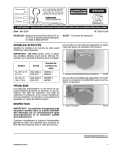
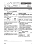
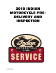
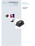
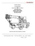
Date: May, 2003
No. 2003-01(W)
MODELS: 2002 & 2003 (SN/ST) Model Year
75 HP through 175 HP Evinrude Direct
Injection Outboards
SUBJECT: Fuel Manifolds
AFFECTED MODELS
A proper weld shows evidence of flashing all the
way around the outside of the cap.
Identify model and serial number before performing any service procedures.
IMPORTANT: DO NOT sell, deliver, or use any
affected models until you have performed the inspection or repair as outlined in this bulletin.
Model
Year
Serial Number
Range
60° V4 75
through 115 HP
2002 (SN) &
2003 (ST)
4996724 through
4999230
60° V6 135
through 175 HP
2002 (SN) &
2003 (ST)
4993888 through
4997951
1
1. Proper weld (flashing around cap)
001732
An incomplete weld shows a lack of or no evidence
of flashing around the outside of the cap.
PROBLEM
The fuel supply or return manifolds could loose an
end cap, resulting in a fuel leak. A fuel leak, when
combined with an ignition source, could result in a
fire or explosion and present a risk of serious personal injury.
1
INSPECTION
IMPORTANT: The inspection and repair procedures outlined in this bulletin MUST be performed by an authorized Evinrude/Johnson
Dealer and Evinrude/Johnson Certified Technician.
1. Incomplete weld
001733
Visually inspect both supply and return fuel manifold assemblies for proper welding at plug area.
Printed in the United States
© 2003 Bombardier Motor Corporation of America. All rights reserved.
TM, ® Trademarks and registered trademarks of Bombardier Motor Corporation of America or its affiliates.
DSS03052B
1 of 6
The use of a flashlight and/or small mirror are recommended to properly inspect the weld area.
To inspect 60° V4 models, remove ignition coils
from bracket and swing them out of the way to view
fuel manifold plug area behind ignition coil bracket.
1
2
60° V4 Model
1. Fuel manifold
2. Plugs (2)
001735
001736
ORDERING PARTS
ONLY Authorized Dealers may order parts.
If replacement is required, replace the fuel manifold assembly with a new fuel manifold assembly
as listed.
To order a new fuel manifold assembly, choose
the correct P/N listed below and fax the order to
847-689-7235.
The order FAX form MUST include the following:
• Date of order
• Dealer Name and Dealer Code
• Dealer Phone Number
• Each Engine Model and Serial Number parts
are needed for.
Please clearly PRINT or TYPE your order on dealer letterhead or paper to ensure efficient order processing.
Parts Needed
1
Fuel Manifold Assembly
2
3
P/N
QTY
60° V4 75 through 115 HP
5005405
1
60° V6 135 through 175 HP
5005408
1
Parts will be shipped at no charge.
REPLACEMENT PROCEDURE
60° V4 Model (Ignition coils removed)
1. Fuel manifold
2. Inspection mirror
3. Flashlight
001737
Wear safety glasses at all times when working on any part of the fuel system.
To inspect 60° V6 models, visually inspect upper
and lower plugs of manifold.
2
1
3
60° V6 Model
1. Plugs (2)
2. Fuel manifold
3. Inspection mirror
4. Flashlight
2 of 6
WARNING
4
001734
Gasoline is extremely flammable and highly
explosive under certain conditions. Use
caution when working on any part of the
fuel system:
• Always disconnect the battery cables at
the battery before servicing the fuel system unless instructed to do otherwise.
• Always work in a well ventilated area
and wipe off any fuel spillage.
• DO NOT smoke and make certain no
open flames or ignition sources exist.
After servicing the fuel system check for
leaks. Failure to check for fuel leakage
could allow a leak to go undetected, resulting in fire or explosion.
RELIEVING FUEL SYSTEM PRESSURE
Disconnect the supply fuel pump connector in the
same manner as the return connector. Drain any
residual fuel remaining in the system into a suitable fuel container.
WARNING
Protect against hazardous fuel spray.
Before starting any fuel system service,
carefully relieve fuel system pressure.
MODELS WITH PRESSURE TEST VALVE
2
Disconnect battery cables at the battery.
Connect fuel pressure gauge, P/N 772959, to
pressure test valve in fuel return manifold.
1
Insert gauge venting hose into suitable container.
Slowly open gauge's venting valve. Clean up any
spilled fuel with shop towels.
MODELS WITHOUT PRESSURE TEST VALVE
Towel removed for clarity
1. Release button
2. Supply fuel pump connector
000703
FUEL MANIFOLD REPLACEMENT
Disconnect battery cables at the battery.
Wrap a shop towel completely around the return
fuel pump connector to minimize fuel spray when
disconnecting.
Press the fuel pump connector release button and
slowly pull the connector off the fuel pump.
Remove high tension spark plug leads and the retainers used to position the spark plug leads.
IMPORTANT: Note the proper locations and positioning of all spark plug leads and retainer clips prior to disassembly.
Mark fuel injectors to indicate cylinder positioning.
Remove the fuel injector retainer screws.
1
Towel removed for clarity
1. Release button
2. Return fuel pump connector
2
2
1
001743
Drain any residual fuel remaining in the system
into a suitable fuel container.
1. Injector retainer
2. Screws
000203
Disconnect all fuel manifold fittings from fuel injector ports and vapor separator/pump assembly.
Remove any tie straps, guards or components
used to secure manifolds in place and remove fuel
manifolds.
1
1. Container
001744
3 of 6
Installation
IMPORTANT: Refer to Evinrude Service Manual,
P/N 5005259, and clean all thread-lock material
residue from the following areas (DO NOT CONTAMINATE INJECTOR PORT OR TIP AREA):
• Injector mounting threads in cylinder head
• Screw threads
Place spring assembly over end of injector. The
pin in the center of the spring should be positioned
in the small O-ring.
Install new fuel manifolds in same position as originals.
1
Position injectors in the proper cylinder location.
Confirm condition of sealing O-rings of fuel manifold fittings. Lubricate with Evinrude direct injection
oil and insert the new fuel manifold fittings into injector. Both fittings must be fully seated into the injector fuel ports.
1. Spring assembly
DP0362
Install large O-ring on inside of injector retainer. Oring can be glued in place with Evinrude/Johnson
Type “M” Adhesive™.
1
2
1. Fuel return manifold fitting
2. Fuel supply manifold fitting
1
000014
Place small O-ring in depression on the end of injector.
1. O-ring
DP0363
Install injector retainer over the end of injector.
IMPORTANT: The flanges on the injector retainer
must engage the outer groove of the fuel manifold
fittings. Be careful not to pinch any wiring or hoses
during assembly.
1
2
1
1. O-ring
DP0361
1. Injector retainer flange
2. Outer groove of fuel manifold fitting
4 of 6
DP0365
Apply Locquic® Primer and Nut Lock™ to the
threads of the injector/fuel fitting screws. Apply a
thin coat of Triple Guard® grease to the two washers and install on each screw. Insert screws with
washers into retainer sleeves.
IMPORTANT: Refer to Predelivery Service Bulletin (D 2002-01) for fuel system purging instructions
and starting procedures. After initial fuel system
pressurization, inspect all fuel system components for leaks and repair as needed before operating engine.
IDENTIFICATION PROCEDURE
2
1
Every outboard that has been inspected, and/or
had replacement fuel rails installed, must be easily
identified.
Mark the engine using WHITE marker or paint.
Place a large dot on both (#1 & #2) cylinder fuel injector cap retainers and on the fuel manifold to
identify this campaign has been completed.
1
1. Screws
2. Washers (two on each screw)
000233
Torque screws in stages, starting with the lower
screw. Final torque is 144 to 168 in. lbs. (16.3 to 19
N·m).
Repeat the above process for the remaining injectors.
Connect the fuel manifolds to vapor separator/pump assembly. An audible click will signal
proper connection. In addition, the fuel pump connector release button should pop out to a flush position.
1. Identification marking
To verify a proper connection, pull on the connector without pressing the release button. The connector should not disconnect from the high
pressure fuel pump.
00204
1
Install tie straps to secure fuel manifolds in place.
Install high tension spark plug leads and the retainers used to position the spark plug leads.
Install any components removed during removal
for access to fuel manifolds.
TYPICAL
1. Identification marking
001742
Thoroughly clean any spilled or residual fuel from
the engine.
WARNING
Failure to check for fuel leakage could allow
a leak to go undetected and, when combined with an ignition source, result in a fire
or explosion.
Reconnect battery cables.
5 of 6
ADDITIONAL INFORMATION
IMPORTANT: If the weld is incomplete OR visual
inspection is inconclusive, replace the fuel manifold assembly as outlined above under REPLACEMENT PROCEDURE.
THE CUSTOMER
Bombardier will send a letter to all registered owners instructing them not to attempt to start or use
the outboard until an authorized Evinrude/Johnson
dealer has completed the inspection or repair. This
is a safety issue.
DEALER RESPONSIBILITY
All dealers, as part of a distribution chain, CARRY
A RESPONSIBILITY TO NOTIFY THE CUSTOMER of any safety related concern and correct the
problem properly.
Please contact all of your customers who have
purchased these outboards and request they return their outboards to your dealership for this service. Only the designated serial numbers are
affected.
A warranty claim form MUST be completed and
submitted along with the following parts:
1) Original fuel return manifold (less rails).
2) Original fuel supply manifold (less rails).
Once removed from the outboard, cut the manifold
from the rails. Thoroughly clean fuel manifolds of
ALL fuel residue and place in a sealed plastic bag
to prevent damaging the claim form. Discard the
fuel rails.
TYPICAL – Fuel manifolds cut from rails
6 of 6
001738
You must return the completed claim with the fuel
manifolds for warranty credit, and to ensure
records are kept for recording program progress to
the U.S.C.G.
Using a standard warranty claim form, use the following information:
• INSPECTION Flat Rate Code – MI03
• REPAIR Flat Rate Code – MR03
• Failing Part Number – 9999945
Flat Rate Labor Allowance:
V4
• Inspection – 0.7 hours
• Replacement – 1.7 hours
V6
• Inspection – 0.5 hours
• Replacement – 1.7 hours
Labor will be paid in accordance with the established warranty labor rates listed in the current
dealer warranty database.
Credit for labor and $10 US to cover shipping and
handling of returned parts will be issued only when
the warranty allowance request form and required
parts are returned. The proper return address is as
follows:
Bombardier Recreational Products
Evinrude/Johnson Dealer Support Services
300 Seahorse Drive/Dock 5
Waukegan, IL 60085
For additional information, dealers can call 1-800888-4662.