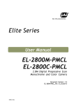
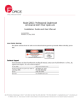
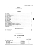
1
Maintenance Instruction
HH Valves Ltd.
Instruction Number: HH47
Revision: 2
Operating & Maintenance
Instruction
Cast Steel Parallel Slide Valve.
Product Number
This Manual covers Valve sizes 5” – 24”, 125mm – 600mm.
The following figures Nos. are included:
5095, 5096, 5099, - FB,PB,RB
L5095, L5096, L5099, - FB,PB,RB
R5095, R5096, R5099, - FB,PB,RB
U5095, U5096, U5099, - FB,PB,RB
For spare parts refer to sheet.
When ordering spares, quote full product number stamped on nameplate and valve serial
Number.
2
1
0
Rev
Issued
Issued
Issued
Detail
L Aspey
L Aspey
L Aspey
Prep
D Saltmarshe
D Saltmarshe
D. Saltmarshe
Approval
16th April 2008
23rd Nov. 2007
30th March 2005
Date
Sheet 1 of 21
Maintenance Instruction
HH Valves Ltd.
Maintenance Instruction
Instruction Number: HH47
Revision: 2
Index
Introduction
Design Features
Nomenclature
Spare Parts
Product Numbering System
Dismantling Procedure
Maintenance
Lubrication
Assembly Procedure
Removal and Replacement
Handwheel Assembly
Sleeve Coupling
Actuator
Gear Box
Sheet 2 of 21
Maintenance Instruction
HH Valves Ltd.
Maintenance Instruction
Instruction Number: HH47
Revision: 2
Introduction
HH Parallel Slide Pressure Seal Valves are built to high standards of precision and accuracy and must pass rigid
inspection before leaving the factory. It is imperative that the valves you purchase be properly installed, maintained and
operated to ensure optimum performance.
The purpose of this service manual is to instruct installation crews, maintenance foremen and operating personnel in
these fundamentals. This manual should be kept available to these personnel at all times so that they may become
familiar with the details of these valves.
HH Parallel Slide Pressure Seal Valves are intended for high pressure service in fluids approved by the manufacturer.
When despatched from HH Valves Ltd Works, they are guaranteed to be in good condition, however, HH Valves Ltd
cannot assume responsibility for damage to valves due to faulty installation, improper operation or other conditions
beyond our control.
Installation
When the valve arrives you will find an envelope containing a PACKING NOTE: - an itemised statement of all valves and
parts included in the shipment. The Receiving Clerk should check and account for each item on the list. Keep this
PACKING NOTE as part of a permanent record of these valves.
UNLOADING of valves should be done with care – Remember that although a valve is a rugged piece of equipment, it
may still be damaged by abusive handling. Skidded or chocked valves should not be un-skidded until immediately before
installation.
IMPROPER INSTALLATION of a valve can have very serious consequences, resulting in possible malfunction which may
necessitate extensive and costly repairs. Compliance with the following recommendations will do much to assure
optimum performance of the valve after installation.
1.
2.
3.
4.
5.
It is essential to take the necessary precautions to prevent the ingress of foreign debris inside the valve, which
could damage the seating surfaces before and after installation.
Provisions should be made for SUPPORTING THE VALVES and adjacent piping so that pipe line stresses will
not be transmitted to the valve bodies during site welding of the pipe to the valve.
WELDING AND STRESS RELIEVING procedures should conform to the applicable code or standard.
CLEANING OF THE PIPE LINES in which valves are installed and all connecting lines is essential before the
unit is put into operation. Welding beads, scale and foreign debris in the lines can cause damage to the valve
seats and can result in leakage.
INSULATION should not be applied to the valve above the lower edge of the segment ring knockout holes. The
limit of insulation is clearly illustrated on all HH general arrangement valve drawings.
Operation & Maintenance
1.
2.
GLAND LEAKS should be corrected promptly by pulling up on the packing gland. Failure to do this may result in
burnt or damaged packing and inability to stop the leak until new packing is installed.
HH Parallel Slide Pressure Seal Valves have a Back Seat Option on the stem, which seats against a hard face
on the underside of the bonnet. This seat will hold pressure if the both surfaces are clean. However, this is
difficult to determine and consequently packing a valve under pressure is hazardous and not recommended.
Back Seats should only be used when necessary and not regularly. Isolation of the packing in high temperature
Valves can cause the packing to dry out.
Sheet 3 of 21
Maintenance Instruction
HH Valves Ltd.
Maintenance Instruction
3.
4.
5.
Instruction Number: HH47
Revision: 2
LUBRICATION of the yoke sleeve is required periodically. This is accomplished by a grease nipple fitted on the
side of the bridge plate. Lubricant should be added until it starts to extrude around the threads.
RECOMMENDED SPARE PARTS: - See the following section in this manual headed “Spare Parts Classification.”
When ordering on HH Valves for any reason whatsoever, please quote the full PRODUCT NUMBER stamped on
the reference plate which is attached to the body casting on each valve.
When raising pressure at any time in the pipeline system the valve gland and bonnet jacking nuts should be
tightened or “follow up” at regular intervals.
CAUTION
Prevention of Overpressure in Valves
HH Valves draw to attention the risk of excessive overpressure in valve designs capable of isolation in either direction.
The overpressure can be caused by the thermal expansion of water or a fluid medium left inside the valve which is
subsequently heated up. Customers should ensure that steps should be made to prevent such an occurrence, either
through application requirements and/or operation procedures. For example, all steam valves must be drained after
hydrostatic test.
Sheet 4 of 21
Maintenance Instruction
HH Valves Ltd.
Maintenance Instruction
Instruction Number: HH47
Revision: 2
Design Features
To open or close a Parallel slide valve all that is necessary is to move the stem to a position where the discs are
clear of the bore or are completely overlapping the seat. This is, of course, completely different from either a
wedge gate or a screw down valve in which cases sufficient intensity of pressure must be exerted by the stem onto
the seat face to ensure a seal across the valve seat.
In the case of a hand operated parallel slide valve the ‘stem-stop’ prevents the stem from rotating and acts as an indicator
to show the stem position. Unless a valve is of a special design it should only be fully open or shut. It is not necessary, and
is undesirable to ram the stem stop nut against the yoke sleeve since this will do nothing to assist sealing and is merely
wasted effort.
The torque applied to the yoke sleeve varies over the movement of the stem but at no time is there a precise torque to be
exerted to attain a seal. As stated above it is a matter of position only, the sealing is caused by the pressure difference
across the disc.
In case of electrically operated valves a torque is determined to choose an appropriate size of operator and not for control
purposes. The limits of the stem travel are determined solely by the limit switches.
Most electric operators are fitted with a torque limiting switch to make it of general application.
To use a torque switch on a parallel slide valve is no advantage since it is position that matters. The standard torque switch
fitted to the operator is normally set to the maximum torque requirements of the valves to avoid unnecessary damage which
could be caused if debris is left in the system.
At all times it should be remembered that with a parallel slide valve it is never necessary to use extra force at the
end of the stroke to make a seal.
The parallel slide gate valve offers excellent sealing without dependence on mechanical effort.
The two separate discs mounted in the belt-eye have sufficient freedom of movement to allow accurate contact between the
flat lapped faces over the range of expansion of contraction.
When the valve is closed and under pressure, the disc on the outlet side is held in contact with the seat by fluid pressure
and is not dependent upon externally applied force.
The discs, in the closed position and not under pressure are held in contact with the seat by one central spring in a small
valve sizes or by three equally spaced springs in larger sizes. This also applies to the outlet side when the valve is under
pressure.
The principle of seating, using flat parallel seats, means that the disc has only to be traversed to the correct position in order
to provide a tight seal. It is not necessary to apply any additional force on the stem at the end of the closing stroke to flex
any metal. When operating a valve electrically it is position that it is important and not final impact.
Because the discs are free to slide between the seat faces it is virtually impossible to create an overstressed condition
under normal operation.
During valve closure the disc wipes the face of the seat and so avoids trapping debris between sealing faces.
Sheet 5 of 21
Maintenance Instruction
HH Valves Ltd.
Maintenance Instruction
Instruction Number: HH47
Revision: 2
FIG 1
Sheet 6 of 21
Maintenance Instruction
HH Valves Ltd.
Maintenance Instruction
Instruction Number: HH47
Revision: 2
Ref No.
Description.
1 - Body
2 - Bonnet
3 - Cover
4 - Stem
5 - Gland
6 - Seat
30 - Gland Flange
37 - Distance Piece
39 - Stem Stop
48 - Pillar
49 - Belt Eye
51 - Disc
56 - Spring
68 - Gland Packing
76 - Segment Ring
80 - Neck Bush
85 - Pressure Seal Ring
86 - Bonnet Collar
146 - Split Ring
28 - Gland Stud
78 - Gland Nut
28a - Stem Stop Stud
78a - Stem Stop Nut
44 - Jacking Screw
41 - Key
Sheet 7 of 21
Maintenance Instruction
HH Valves Ltd.
Maintenance Instruction
Instruction Number: HH47
Revision: 2
Classification Of Spare Parts
The following is the classification of Replacement Spare Parts for HH Parallel Slide Valves.
Classification
Item Number
Description
Commissioning Spares
68
85
Gland Packing
Pressure Seal
Parts Required for
Periodic Maintenance
Item Number
Description
4
5
51
56
80
Other Parts
Item Number
*
11
30
39
48
44
159
+
Fasteners
Item Number
Stem
Gland
Disc
Spring
Neck Bush
Description
Yoke Sleeve
Gland Flange
Stem Stop
Pillar
Jacking Stud
Drive Nut
Description
(E.g. Nuts, Bolts, Pins etc.)
* Hand Operated valves and sleeve Coupling
+ Used on Actuator and gearboxes
Sheet 8 of 21
Maintenance Instruction
HH Valves Ltd.
Maintenance Instruction
Instruction Number: HH47
Revision: 2
Dismantling Procedure
1. Ensure there is no pressure in the pipeline or valve. The pipeline should be drained
prior to dismantling valve.
2. Open valve to halfway position.
3. Remove operating module (handwheel, actuator etc.) as detailed in the relevant
appendix.
4. Remove stem stop nuts (28a) and stem stop studs (78a).
5. Remove split stem stop (39), together with key (41).
6. Remove gland nuts (28), gland flange (30) and gland (5).
7. Loosen jacking studs (44) and knock down bonnet collar (86), which will enable split
ring (146) to be removed.
8. Remove bonnet collar together with jacking screws.
9. Remove cover.
10. Using a soft faced hammer, tap down bonnet (2) to clear segment ring (76).
11. Insert punch into knock out holes in valve body and remove segment (76) as
illustrated in Fig. 2.
Sheet 9 of 21
Maintenance Instruction
HH Valves Ltd.
Maintenance Instruction
Instruction Number: HH47
Revision: 2
12. Replace cover (3), bonnet collar (86), split ring (146).
13. Tighten down on jacking screws (44). This will jack bonnet, together with distance
piece (37), and pressure seal (85), out of the valve body. When bonnet becomes free
lift the assembly clear of the body.
14. Dismantle bonnet assembly, then remove gland packing (68), neck bush (80),
distance piece (37), and pressure seal ring (85) from bonnet.
15. Lift out stem/belt eye assembly (4, 49) together with the discs (51) and spring(s)
(56).(on some sizes 3 springs are fitted.)
16. Remove stainless steel wire from disc clips and unscrew disc clips, then remove discs
FIG 3
Sheet 10 of 21
Maintenance Instruction
HH Valves Ltd.
Maintenance Instruction
Instruction Number: HH47
Revision: 2
Maintenance
Seat and Disc Maintenance
Abrasions between the seat and disc faces are inevitable after long periods in service, and to
maintain fluid tightness and ease of operation, it is recommended that the following procedure is
adopted, when the valve is under repair.
Refacing the Valve Disc by Lapping
A slightly pitted or scored disc face may be restored by lapping on a flat cast iron plate.
Ensure that the plate and disc are clean, apply a thin layer of lapping paste on the lap, operate the
disc gently over the plate using a figure-of-eight motion.
Continue lapping until a good face is obtained.
It is essential to ensure that the lapping plate face is kept perfectly flat.
Re-facing the Valve Disc by Machining
Should the disc face be found so badly scored that it cannot be restored by lapping, it will be
necessary to machine the face.
Mount the disc in the lathe, carefully check with a dial test indicator, remove just sufficient metal to
obtain a clean flat face, finally lap as previously described. Minimum thickness of hard face deposit is
1.6mm (1/16”.)
Sheet 11 of 21
Maintenance Instruction
HH Valves Ltd.
Maintenance Instruction
Instruction Number: HH47
Revision: 2
Re-facing Body Seats
To assist in maintenance of valves which are inline a pneumatically operated lapping
machine can be supplied for refurbishing the seats. A Trained Service Engineer can attend
site equipped to lap body seats with the valve in situ.
Lubrication
Lubricate stem threads and hand operating
gear with high temperature (350 F / 177 C)
Lithium based grease, preferably with a MoS2 addition
at 3 monthly intervals. Lubricate actuators and
gearboxes etc. according to individual
manufacturers instructions.
Sheet 12 of 21
Maintenance Instruction
HH Valves Ltd.
Maintenance Instruction
Instruction Number: HH47
Revision: 2
Re-facing Stem & Bonnet Backseat
The backseat faces can be refurbished by using a cast iron lap.
Sheet 13 of 21
Maintenance Instruction
HH Valves Ltd.
Maintenance Instruction
Instruction Number: HH47
Revision: 2
Assembly Procedure
Bonnet:
1. Remove distance piece and old pressure seal from the bonnet. Inspect the seal area of the
bonnet for washing or steam cuts. The joint will take up minor defects, but if in doubt, change
the bonnet.
2. Remove the gland packing, inspect the internal surface of the stuffing box again for the steam
cuts or pitting.
3. Check neck bush for wear; if damaged, neck bush must be replaced.
Note:
It is not recommended that either gland packing or pressure seal is re-used.
Stem
1. Check stem threads for wear, also inspect the finish of the stem which operates through the gland.
It must be smooth and free from scoring.
Body
Ensure that the body is cleaned to remove any residue of lapping paste or any other foreign debri
which may have accumulated in the valve body.
Sheet 14 of 21
Maintenance Instruction
HH Valves Ltd.
Maintenance Instruction
Instruction Number: HH47
Revision: 2
Assembly Procedure
1. Assemble discs, springs and disc clips into stem and belt eye assembly, distance over
the seats to be as the attached table
2.
3.
4.
5.
6.
7.
8.
Lay one disc on a clean flat surface
Locate the belt eye on the disc
Fit spring(s) into the disc recess
Place the other disc on top of the spring(s) ensuring location in recess
Clamp the discs together as shown
Measure & record the distance between the seats in the body
Adjust the clamp so that dim. A is set to the distance between seats plus the
dimension in the table.
Sheet 15 of 21
Maintenance Instruction
HH Valves Ltd.
Maintenance Instruction
9
10
11
12
Instruction Number: HH47
Revision: 2
Insert disc clips studs into the belt eye
Screw disc clips into the studs until the clips make contact with the disc
shoulder
Line up the grooves in the disc clips and stud
Remove clamp before inserting in the valve body.
Sheet 16 of 21
Maintenance Instruction
HH Valves Ltd.
Maintenance Instruction
Instruction Number: HH47
Revision: 2
13. Fit new pressure seal ring (85) onto bonnet (2), then lower over stem into valve body.
14. Fit distance piece (37) and segment ring (76).
15. Fit Cover (3).
16. Lower bonnet collar (86) over bonnet then fit split ring (146)
17. Screw jacking screws (44) into bonnet collar and tighten down evenly to effect
compression on pressure seal.
18. Fit neck bush (80), gland packing (68), and gland (5) into bonnet stuffing box.
19. Fit gland flange (30) and gland nuts (28), then tighten nuts evenly.
20. Fit key (41) into stem then assemble stem stop (39), and secure with studs (28a)
and nuts (78a).
21. Fit operating module as detailed in the relevant appendix.
22. Stroke valve fully open and shut, to check ease of operation.
Notes:
A. The gland stuffing box is designed to accept only die moulded expanded
graphite packing rings. No other packing material may be used.
B. It will be necessary to tighten (follow up) pressure seal and gland packing at
regular intervals when raising pressure I the system for the first time. This can
be achieved by tightening jacking studs and gland nuts respectively.
Sheet 17 of 21
Maintenance Instruction
HH Valves Ltd.
Maintenance Instruction
Instruction Number: HH47
Revision: 2
Appendix 1
Removal and Replacement – Handwheel Assembly
To remove Handwheel Assembly from valve
1. Remove Cap Head Screws, and Safety Washers.
2. Turn handwheel in a clockwise direction until bridge/handwheel assembly disengages
from valve stem.
To Replace Assembly
1. Locate yoke Sleeve onto valve stem.
2. Turn handwheel in an anti clockwise direction until bridge locates onto the pillars.
3. Fit safety washers and Cap Head Screws.
Sheet 18 of 21
Maintenance Instruction
HH Valves Ltd.
Maintenance Instruction
Instruction Number: HH47
Revision: 2
Appendix 2
Removal and Replacement of Sleeve Coupling
To Remove Sleeve Coupling Assembly From Valve
1. Remove cap head screws and safety washers.
2. Rotate sleeve coupling in a clockwise direction until the assembly disengages from
valve stem.
To Replace Assembly
1. Locate yoke sleeve onto valve stem.
2. Rotate sleeve coupling in anti-clockwise direction until bridge locates onto pillars.
3. Fit safety washers and cap head screws.
Sheet 19 of 21
Maintenance Instruction
HH Valves Ltd.
Maintenance Instruction
Instruction Number: HH47
Revision: 2
Appendix 3
Removal and replacement of Actuator.
Before dismantling any valve with actuators, ensure that the electrical supply has been isolated and then travel
limits inside the actuator have been disconnected.
To Dismantle:
Using lifting tackle, place a sling around the actuator and exert a very slight load on the hoist. Unscrew all the
cap head allen screws under the bridge plate and remove from actuator.
Engage the handwheel on actuator and turn in a clockwise direction, this will separate the actuator from the
bridge plate. Lift the actuator completely away when the thread of the drive nut disengages from the thread of
the spindle. Care must be taken not to put any strain on the electrical cables.
To Assemble:
Replace the actuator by reversing the above procedure and turning the handwheel in and anti-clockwise
direction.
Actuator Limits
When setting the actuator limits close the valve fully then open valve one complete turn and set the close limits.
Open the valve fully to the indicator marks on the pillars, then close the valve one complete turn and set the
open limits. By doing this operation when the valve opens or shuts, the stem stop will not hit the pillar stops and
damage the stem stop, stem and drive nut.
Sheet 20 of 21
Maintenance Instruction
HH Valves Ltd.
Maintenance Instruction
Instruction Number: HH47
Revision: 2
Appendix 4
Removal and Replacement of Gearbox
To Dismantle
1. Remove all cap head Allen screws and safety washer from the bridge.
2. Turn the input in a clockwise direction to separate the gearbox from the bridge.
3. Continue turning input shaft until the thread in the gearbox drive nut disengages from the tread on the
stem.
4. Lift gearbox clear of the valve and lower to a safe location.
To Assemble.
1. Fit gearbox squarely over stem.
2. Turn input shaft in an anti-clockwise direction until the tread on the drive nut engages the thread on the
stem.
3. Continue to turn the input shaft until gearbox flange mates with bridge.
4. Re-fit cap head Allen screws and safety washers and tighten up.
Sheet 21 of 21