1
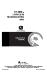
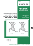
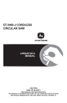
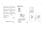
MODEL
UC 24YFA
POWER TOOLS
CHARGER
UC 24YFA
TECHNICAL DATA
AND
SERVICE MANUAL
U
LIST No. F845
Mar. 2001
SPECIFICATIONS AND PARTS ARE SUBJECT TO CHANGE FOR IMPROVEMENT
CONTENTS
Page
1. PRODUCT NAME ........................................................................................................................... 1
2. MARKETING OBJECTIVE ............................................................................................................. 1
3. APPLICATIONS .............................................................................................................................. 1
4. SELLING POINTS .......................................................................................................................... 2
4-1. Selling Point Descriptions ............................................................................................................... 3
5. SPECIFICATIONS .......................................................................................................................... 7
5-1. Specifications .................................................................................................................................. 7
5-2. Comparisons with Similar Products ................................................................................................ 7
6. PRECAUTIONS IN SALES PROMOTION ..................................................................................... 8
6-1. Safety Instructions .......................................................................................................................... 8
6-2. Extra Precautions in Sales Promotion ............................................................................................ 9
7. QUESTIONS AND ANSWERS ON MODEL UC 24YFA .............................................................. 10
8. GENERAL PRECAUTIONS ......................................................................................................... 13
8-1. Model UC 24YFA .......................................................................................................................... 13
8-2. Pilot Lamp Indications ................................................................................................................... 14
9. PRECAUTIONS IN DISASSEMBLY AND REASSEMBLY .......................................................... 15
9-1. Disassembly ................................................................................................................................ 15
9-2. Reassembly .................................................................................................................................. 15
9-3. Confirmation after Reassembly .................................................................................................... 15
10. TROUBLESHOOTING GUIDE ................................................................................................... 16
10-1. Troubleshooting Based on Pilot Lamp Indications ...................................................................... 16
10-2. Troubleshooting and Repair Procedures .................................................................................... 16
11. STANDARD REPAIR TIME (UNIT) SCHEDULES...................................................................... 20
Assembly Diagram for UC 24YFA
1. PRODUCT NAME
Hitachi Charger, Model UC 24YFA
2. MARKETING OBJECTIVE
As the cordless tool market expands year by year, customers have come to expect a wider range of high-voltage
products, longer run time with high-capacity batteries, and lower prices. The Model UC 24YFA, a rapid and lowprice charger, has been developed by making improvements to the current Model UC 24YF that is capable of
recharging both nickel cadmium (Ni-Cd) and nickel metal hydride (Ni-MH) batteries from 7.2 V to 24 V in one hour.
3. APPLICATIONS
Recharging of Hitachi batteries
Applicable batteries:
Ni-Cd batteries
EB 7
EB 9
EB 12
EB 7S
EB 9S
EB 12S
EB 14S
EB 7G
EB 9G
EB 12G
EB 9B
EB 12B
EB 14B
EB 18B
EB 1820
EB 24B
EB 9M
EB 12M
EB 924
EB 1224
EB 1424
EB 1414
EB 1814
[7.2 V,
[9.6 V,
[12 V,
[7.2 V,
[9.6 V,
[12 V,
[14.4 V,
[7.2 V,
[9.6 V,
[12 V,
[9.6 V,
[12 V,
[14.4 V,
[18 V,
[18 V,
[24 V,
[9.6 V,
[12 V,
[9.6 V,
[12 V,
[14.4 V,
[14.4 V,
[18 V,
1.3 Ah]
1.3 Ah]
1.3 Ah]
1.3 Ah]
1.3 Ah]
1.3 Ah]
1.3 Ah]
1.7 Ah]
1.7 Ah]
1.7 Ah]
2.0 Ah]
2.0 Ah]
2.0 Ah]
2.0 Ah]
2.0 Ah]
2.0 Ah]
2.0 Ah]
2.0 Ah]
2.4 Ah]
2.4 Ah]
2.4 Ah]
1.4 Ah]
1.4 Ah]
Ni-MH batteries
EB 9H
EB 12H
EB 14H
EB 930H
EB 1230H
EB 1430H
EB 1830H
EB 2430H
[9.6 V,
[12 V,
[14.4 V,
[9.6 V,
[12 V,
[14.4 V,
[18 V,
[24 V,
2.2 Ah]
2.2 Ah]
2.2 Ah]
3.0 Ah]
3.0 Ah]
3.0 Ah]
3.0 Ah]
3.0 Ah]
1
4. SELLING POINTS
(1) Accepts both Ni-MH and Ni-Cd batteries
(2) Rapidly charges all Hitachi EB-series batteries
Charging time:
1.3 Ah
• • • • • • • • • • • • • • • • •
35 minutes
2.0 Ah
• • • • • • • • • • • • • • • • •
50 minutes
1.4 Ah
• • • • • • • • • • • • • • • • •
40 minutes
2.2 Ah
• • • • • • • • • • • • • • • • •
55 minutes
1.7 Ah
• • • • • • • • • • • • • • • • •
45 minutes
2.4 Ah
• • • • • • • • • • • • • • • • •
60 minutes
3.0 Ah
• • • • • • • • • • • • • • • • •
70 minutes
(3) Hitachi original charge control mechanism for longer battery life
Recharging/discharging cycles of battery
(ambient temperature range between 10 ˚C and 30 ˚C)
• Ni-Cd: about 1,000 times
• Ni-MH: about 500 times
General-purpose charger capable of
recharging 7.2 V to 24 V batteries
EB 7
EB 7S
EB 9
EB 9S
EB 9B
EB 9M
EB 924
EB 9H
EB 930H
EB 12
EB 12S
EB 12B
EB 12M
EB 1224
EB 12H
EB 1230H
EB 1414
EB 14S
EB 14B
EB 1424
EB 14H
EB 1430H
EB 1814
EB 1830H
EB 1820
EB 18B
EB 24B
EB 2430H
3-way overcharging protection
systems for longer battery and
charger life
Easy-to-read visual display of charging
status through constant lighting or flashing
of red and green pilot lamps
Fig. 1
2
4-1. Selling Point Descriptions
4-1-1. Capable of handling both nickel cadmium (Ni-Cd) and nickel metal hydride (Ni-MH) batteries
Through application of HITACHI-microcomputer and electronic-circuit control technology, Model UC 24YFA is
capable of handling both Ni-Cd and Ni-MH batteries.
4-1-2. Rapidly charges all Hitachi EB-series batteries:
Recharging time for 2.0 Ah battery has been reduced to approx. 50 minutes and 3.0 Ah battery to approx. 70
minutes. Table 1 shows the charging time for each battery.
Table 1 Recharging time (approx. min.) at 20 ˚C
Battery
voltage
(V)
7.2 V
9.6 V
12 V
14.4 V
18 V
Battery capacity (Ah)
1.3 Ah
EB7
1.4 Ah
35 min.
EB7S
EB9
35 min.
EB9S
EB12
35 min.
1.7 Ah
EB7G
45 min.
EB9G
45 min.
EB9B
EB12G 45 min.
EB12S
EB14S 35 min. EB1414 40 min.
EB1814 40 min.
24 V
2.0 Ah
2.2 Ah
2.4 Ah
3.0 Ah
70 min.
50 min. EB9H
55 min. EB924
60 min. EB930H
50 min. EB12H
55 min. EB1224
60 min. EB1230H 70 min.
EB14B 50 min. EB14H
55 min. EB1424
60 min. EB1430H 70 min.
EB9M
EB12B
EB12M
EB1820
50 min.
EB1830H 70 min.
EB24B 50 min.
EB2430H 70 min.
EB18B
: Ni-MH batteries
NOTE: The recharging time may vary according to the ambient temperature and the power supply voltage.
4-1-3. Recharging/discharging cycles of battery (ambient temperature range between 10 ˚C and 30 ˚C)
• Ni-Cd battery: about 1,000 times
• Ni-MH battery: about 500 times
4-1-4. Capable of recharging batteries with internal temperatures as high as 60 ˚C
When a battery with S terminal is used, as shown in Fig. 3 and Fig. 4, the 60 ˚C thermistor operates to permit
recharging of batteries heated up to 60 ˚C, and as shown in Fig. 5 and Fig. 6, the 55 ˚C thermistor operates
heated up to 55 ˚C.
(Note 1) • Wiring diagrams for batteries are shown below.
• The 95 ˚C thermal protector in the batteries EB 14S, EB 14B, EB 1424, EB 14H, EB 1430H, EB 18B,
EB 24B and EB 2430H interrupts the recharging circuit when the battery temperature reaches 95 ˚C.
• A discriminating resistor is provided in Ni-MH batteries EB 9H, EB 930H, EB 12H, EB 1230H,
EB 14H, EB 1430H and EB 2430H to distinguish them from Ni-Cd batteries.
• Because Ni-MH batteries EB 9H, EB 930H, EB 12H, EB 1230H, EB 14H, EB 1430H and EB 2430H
are heated to high temperatures during recharging, this charger operates within a range of a 10 ˚C
temperature difference between the maximum battery temperature when starting recharging (45 ˚C)
and the temperature when stopping recharging (55 ˚C).
3
60 ˚C Thermistor (Models UC 24YC, UC 24 YF, UC 14YF2,
UC 14YF, UC 12YF, UC 12YD and
UC 12YB) 40 ˚C Thermostat
(Models UC 12Y and UC 12YA)
40 ˚C Thermostat
+ Terminal
T
+ Terminal
Terminal
-- Terminal
(Terminal positions)
T
Terminal
S
Terminal
-- Terminal
(Terminal positions)
Fig. 2 Ni-Cd batteries (EB 7, EB 9 and EB 12)
Fig. 3 Ni-Cd batteries (EB 7S, EB 9S and EB 12S,
EB 7G, EB 9G, EB 12G, EB 9B, EB 12B, EB
9M, EB 12M, EB 924 and EB 1224)
95 ˚C Thermal protector
60 ˚C Thermistor
+ Terminal
S
Terminal
-- Terminal
-- Terminal
(Terminal positions)
Fig. 4 Ni-Cd batteries (EB 14S, EB 14B, EB 1424, EB 1414,
EB 1814, EB 1820, EB 18B and EB 24B)
95 ˚C Thermal protector
Discriminating
resistor
Discriminating resistor
55 ˚C Thermistor
+ Terminal
+ Terminal
S
Terminal
T
Terminal
Terminal
T
Terminal
-- Terminal
(Terminal positions)
-- Terminal
Fig. 5 Ni-MH batteries (EB 9H, EB 12H, EB 930H,
and EB 1230H)
S
55 ˚C Thermistor
-- Terminal
(Terminal positions)
Fig. 6 Ni-MH batteries (EB 14H, EB 1430H,
EB 1830H and EB 2430H)
4
4-1-5. 3-way overcharge protection system
Overcharge protection is ensured by a (A)
system or dT/dt system (for Ni-MH battery), (B) built-in battery
temperature sensors (thermostat and thermistor) and (C) a timer.
Overcharge range
2
V
Battery internal gas pressure
Battery temperature
Battery voltage
Battery voltage
55˚C Thermistor
dT/dt
60˚C Thermistor
40˚C Thermostat
Ni-MH Battery
temperature
30~60-Minute timer
Ni-Cd Battery temperature
Charging time
Battery internal
gas pressure
Fig. 7 Relationships of time, voltage, temperature and gas pressure while charging
(A) •
: This detects the increase in battery voltage at the end of charging using the value
and suspends
charging.
dT/dt : This system is applicable to Ni-MH batteries. This detects the variation of Ni-MH battery temperature
by the value dT/dt at the end of charging and suspends charging.
(B) • Built-in battery temperature sensors : In the event the
system fails to detect the voltage change,
the 40 ˚C thermostat or the 60 ˚C thermistor stops charging when battery temperatures reach their respective
values.
(C) • Timer : Should both the
system, dT/dt system and the temperature sensors fail, the timer automatically
stops charging within 120 minutes from the beginning of charging.
(Note 2) The voltage of the battery increases during charging and begins to fall when further charging is not
possible. The
system detects the point where the voltage begins to fall, and suspends charging
to protect the battery from overcharging.
(Note 3) The temperature rise during charging of a Ni-MH battery is higher than with a Ni-Cd battery, and a
sudden temperature rise occurs just before the battery is fully charged. The dT/dt system detects the
point where the temperature rises suddenly and suspends charging to minimize the temperature rise.
(Note 4) As shown in Fig. 7, the pressure of gas generated after a battery has become fully charged rises
rapidly to cause high temperature and high gas pressure that degrade the effectiveness of the
battery. If charging is allowed to continue, the pressure of the gas will activate the safety valve in the
battery, and the electrolyte will begin leaking.
5
4-1-6. Easy-to-read visual display of charging status through constant lighting or flashing of red and green pilot
lamps
Pilot lamp indications
Red pilot lamp
remains lit or
flashes
Green pilot
lamp is lit
Prior to charging
Blinks
During charging
Lights
Charging
completed
Blinks
Charging not
possible
Flickers
High battery
temperature
Lights
0.5 sec. ON
0.5 sec. OFF
Stays ON constantly
0.5 sec. ON
0.5 sec. OFF
0.1 sec. ON
0.1 sec. OFF
Stays ON constantly
Battery or charger
is faulty.
Charging not possible
because battery
temperature is too high.
Charging of heated (high temperature) batteries
Battery Type
Battery temperature
range during charging
Heated (high temperature) battery
EB 7, EB 9, EB 12
---5 ˚C --- 40 ˚C
Green pilot lamp lights. When battery
temperature is reduced to 40 ˚C,
green pilot lamp goes OFF and
charging begins.
EB 7S, EB 7G, EB 9S, EB 9G, EB 9B,
EB 9M, EB 924, EB 12S, EB 12G, EB 12B,
EB 12M, EB 1224, EB 14S, EB 1414, EB 14B,
EB 1424, EB 1814, EB 18B, EB 1820, EB 24B
---5 ˚C --- 60 ˚C
Green pilot lamp lights. When battery
temperature is reduced to 60 ˚C,
green pilot lamp goes OFF and
charging begins.
0 ˚C --- 45 ˚C
Green pilot lamp lights. When battery
temperature is reduced to 45 ˚C,
green pilot lamp goes OFF and
charging begins.
EB 9H, EB 930H
EB 12H, EB 1230H
EB 14H, EB 1430H, EB 1830H, EB 2430H
6
5. SPECIFICATIONS
5-1. Specifications
Item
Descriptions
Power source
AC single-phase, 50 Hz or 60 Hz
Power input
90 W
Charging system
Constant current charge with feedback control
Overcharging protection system
(1) Battery voltage detection (
system) for Ni-Cd battery
Ni-MH battery temperature detection (dT/dt system) for Ni-MH battery
(2) Battery surface temperature detection (thermostat or thermistor)
(3) 120 minutes timer
Charging voltage
7.2 V --- 24 V
Charging current
2.5 A
Charging time
Approx. 50 minutes (for 2.0 Ah)
Product weight
0.6 kg
Operating ambient
temperature range
0 ˚C --- 40 ˚C
5-2. Comparisons with Similar Products
HITACHI
B
UC 24YFA
Charging time
min.
50
(2.0 Ah)
50
(2.0 Ah)
Charging voltage
V
7.2 --- 24
7.2 --- 24
Charging current
A
2.5
2.5
Power input
W
90
(90)
Operating ambient
temperature range
˚C
0 --- 40
4 --- 41
Chargeable battery
temperature range
˚C
(*1) ---5 --- 60
(*2) 0 --- 45
4 --- 41
Overcharge protection
system
---
system, dt/dt system,
battery surface
temperature detection,
timer
Peak cut
mm
226 x 110 x 75
118 x 154 x 80
kg
0.6 (1.3 lbs.)
0.6 (1.3 lbs.)
External dimensions
(length x width x height)
Weight
(*1): Chargeable Ni-Cd battery temperature range
(*2): Chargeable Ni-MH battery temperature range
7
6. PRECAUTIONS IN SALES PROMOTION
6-1. Safety Instructions
In the interest of promoting the safest and most efficient use of the Model UC 24YFA Charger by all of our
customers, it is very important that at the time of sale the salesperson carefully ensures that the buyer seriously
recognizes the importance of the contents of the Handling Instructions.
6-1-1. Handling instructions
Salespersons must be thoroughly familiar with the contents of the Handling Instructions in order to give pertinent
advice to the customer.
(1) Connect the charger to an AC power outlet only.
Use of any other power source (DC outlet, fuel-powered generator, etc.) will cause the charger to overheat
and burn out.
(2) Do not use any voltage-increasing equipment (transformer, voltage regulator, etc.) between the power source
and the charger.
If the charger is used with voltage over and above that indicated on the unit, it will not function properly.
(3) Conduct battery charging in an ambient temperature range of 0 ˚C --- 40 ˚C.
If charging is attempted when the ambient temperature is below 0 ˚C, overcharging occurs because the
thermistor and thermostat do not function properly, thereby reducing the service life of the battery.
If charging is attempted when the ambient temperature is above 40 ˚C, charging is not possible for the EB 7,
EB 9 and EB 12 batteries because the thermostat is immediately activated to stop charging.
While it is possible to charge batteries with an S terminal at higher temperatures, the service life of the
batteries may be considerably reduced.
(4) Do not use the charger for successive charging.
In very hot locations, if two or more batteries are charged successively the temperature of the charger will rise
excessively, and might cause the charger to fail. Instruct the customer to wait at least 15 minutes before
commencing next charging. Particular care is necessary in summer or tropical countries when the power
source voltage is high.
(5) Do not insert foreign objects into the air vent on the charger.
The charger case is equipped with air vents to protect the internal electronic components from overheating.
Caution the customer not to allow foreign materials, such as metallic or inflammable objects, to be dropped or
inserted into the air vents. This could cause electrical shock, fire or other serious hazards.
(6) Do not attempt to disassemble the charger.
Incorrect parts replacement and/or wiring will cause malfunctions which could result in fire or other hazards.
Instruct the customer to bring the charger to an authorized service center in the event repair or replacement is
necessary.
8
6-2. Extra Precautions in Sales Promotion
The following points must be given during sales promotion.
6-2-1. Charging may not be possible when the battery temperature is high
Charging may not be possible if the temperature of the battery is high after it has been exposed to direct sunlight for
a long time or immediately after it has been used.
The customer should be advised in such a case to place the battery in a shaded area with good airflow, and allow
sufficient cooling before recharging. This phenomenon is common to all existing batteries and chargers which
employ temperature sensitive overcharge protection devices. The cooling time required before recharging varies
from a few minutes to about 30 minutes, depending on the load, duration of use and ambient temperature.
6-2-2. Inserting a battery into a charger in reverse direction can cause serious damage to the battery and the
charger
Inadvertently inserting a battery into the charger in the reverse direction will not only make it impossible to charge
the battery, it can also cause such damage as deformed terminals on the charger and the battery. Customers
should be advised to confirm that the battery terminals are correctly aligned before inserting the battery into the
charger.
6-2-3. B-2 (7.2 V) and B-3 (9.6 V) batteries cannot be recharged with the Model UC 24YFA
(1) Because the shape of the B-2 (7.2 V) battery is different from others, it cannot be connected to the Model
UC 24YFA.
(2) Even if the B-3 (9.6 V) battery is connected to the Model UC 24YFA using the optional accessory adapter,
recharging is not possible because the internal wiring of the battery is different from the others.
9
7. QUESTIONS AND ANSWERS ON MODEL UC 24YFA
Q1 What are typical charging methods?
UC 12Y
UC 12YA
Method B
Battery voltage
Method A
UC 24YFA
UC 24YFB
Charging time
The descending voltage ( --) of
the battery in the final stage of
charging is detected, and charging
is automatically suspended.
Method C
UC 24YFA
UC 24YFB
Battery temperature
---
UC 24YC
UC 24YF
UC 14YF2
UC 14YF
UC 12YF
UC 12YD
UC 12YB
Charging method
Battery voltage
A1 The most recent electronic charging methods are outlined below.
Charging time
Voltage variation factor immediately
before battery becomes fully
charged is detected, and charging
is automatically suspended.
Charging method
dT/dt
UC 24YC
Charging time
Sudden temperature rise just
before full charging is detected and
charging is suspended (Ni-MH
battery)
dT/dt Charging method
10
Q2 Why was the
microcomputer control system adopted for the Model UC 24YFA?
A2 If charging is continued after the battery has been fully charged, it will cause a large amount of oxygen gas
(O2) to be generated in a short period of time, as shown below. This proportionately accelerates
degradation of the plates.
The
microcomputer control system was adopted for the Model UC 24YFA charger in order to stop
charging immediately before the battery is fully charged, thereby avoiding the generation of oxygen gas.
This charging method applies no stress to the batteries.
O2
Anode plate
Anode plate
Cathode plate
Cathode plate
Up to full charge. (Charging
proceeds almost without
deviation.)
Charged portion
Anode plate
O2
O2
Separator
Oxygen gas is generated
when full charge is reached.
(Anode is fully charged.)
Cathode plate O2 O2 O2
Enters overcharge state and
begins gas degradation with the
cathode.
Uncharged portion
Plates
Q3 What is the difference between the
microcomputer control system and the dT/dt system?
A3 Both systems cut off charging at almost the same point before the battery becomes fully charged.
The
microcomputer control system detects a sudden voltage change which occurs just before the
battery is fully charged and then suspends charging. The dT/dt system detects a sudden temperature rise
which occurs just before the battery is fully charged and then suspends charging.
Q4 Is there any difference in the amount of work possible per charge of batteries charged with the
microcomputer control system and those charged with dT/dt microcomputer control system?
A4 The dT/dt microcomputer control system may have a slightly shorter charging capacity (approx. 3 to 5 %).
However, the amount of work possible per charge varies widely depending on the ambient temperature, the
efficiency with which the battery charge is used, etc., so that there is essentially no difference between
batteries charged with either system.
Q5 The battery charger is supposed to be used within a temperature range of 0 to 40 ˚C.
What happens if it is used for charging at under 0 ˚C or above 40 ˚C?
A5 At temperatures of under 0 ˚C, battery overcharge will occur, resulting in damage to the battery plates
because the plates may not function properly. At temperatures over 40 ˚C, sufficient charging cannot be
attained, or the plates will be damaged and the recharging/discharging cycles of the batteries will be
reduced by half compared to low-temperature charging, even if the battery is fully recharged.
11
Q6 What is the relationship between the upper limit of the chargeable temperature of the battery and of
the battery charger?
A6 Relationships are indicated in the following table:
Ni-Cd Battery
Ni-MH Battery
EB 7
EB 9
EB 12
EB 7S, EB 7G
EB 9S, EB 9B, EB 9M
EB 924, EB 12S
EB 12G, EB 12B
EB 12M, EB 1224
EB 14S
EB 1414
EB 14B
EB 1424
EB 18B
EB 1814
EB 1820
EB 24B
EB 9H, EB 930H
EB 12H, EB 1230H
EB 14H, EB 1430H
EB 1830H
EB 2430H
UC 24YFA
40 ˚C
60 ˚C
60 ˚C
60 ˚C
45 ˚C
45 ˚C
UC 24YC
40 ˚C
60 ˚C
60 ˚C
60 ˚C
45 ˚C
45 ˚C
UC 24YF
40 ˚C
60 ˚C
60 ˚C
60 ˚C
45 ˚C
45 ˚C
UC 14YF2
40 ˚C
60 ˚C
60 ˚C
Charging
impossible
45 ˚C
Charging
impossible
UC 14YF
40 ˚C
60 ˚C
60 ˚C
Charging
impossible
Charging
impossible
Charging
impossible
UC 12YF
40 ˚C
60 ˚C
Charging
impossible
Charging
impossible
Charging
impossible
Charging
impossible
UC 12YD
40 ˚C
60 ˚C
Charging
impossible
Charging
impossible
Charging
impossible
Charging
impossible
UC 12YB
40 ˚C
60 ˚C
Charging
impossible
Charging
impossible
Charging
impossible
Charging
impossible
UC 12Y
40 ˚C
40 ˚C
Charging
impossible
Charging
impossible
Charging
impossible
Charging
impossible
UC 12YA
40 ˚C
40 ˚C
Charging
impossible
Charging
impossible
Charging
impossible
Charging
impossible
12
8. GENERAL PRECAUTIONS
8-1. Model UC 24YFA
(1) The outer frame consists of case (A) and case (B). Inside the frame there are the printed circuit board and
terminals.
(2) The printed circuit board consists of high-frequency power transformer, microcomputer and other electronic
devices to permit rapid charging and to protect against overcharging.
Case (A)
Terminal
Printed circuit board
Case (B)
Case (A)
Terminal
Case (B)
13
8-2. Pilot Lamp Indications
Pilot lamp indications
Red pilot lamp
remains lit or
flashes
Green pilot
lamp is lit
Prior to charging
Blinks
During charging
Lights
Charging
completed
Blinks
Charging not
possible
Flickers
High battery
temperature
Lights
0.5 sec. ON
0.5 sec. OFF
Stays ON constantly
0.5 sec. ON
0.5 sec. OFF
0.1 sec. ON
0.1 sec. OFF
Stays ON constantly
Battery or charger
is faulty.
Charging not possible
because battery
temperature is too high.
Pilot lamp indications during charging of heated (high temperature) batteries
Battery Type
Battery temperature
range during charging
Heated (high temperature) battery
EB 7, EB 9, EB 12
---5 ˚C --- 40 ˚C
Green pilot lamp lights. When battery
temperature is reduced to 40 ˚C,
green pilot lamp goes OFF and
charging begins.
EB 7S, EB 7G, EB 9S, EB 9G, EB 9B, EB 9M,
EB 924, EB 12S, EB 12G, EB 12B, EB 12M,
EB 1224, EB 14S, EB 1414, EB 14B, EB 1424,
EB 1814, EB 18B, EB 1820, EB 24B
---5 ˚C --- 60 ˚C
Green pilot lamp lights. When battery
temperature is reduced to 60 ˚C,
green pilot lamp goes OFF and
charging begins.
EB 9H, EB 930H
EB 12H, EB 1230H
EB 14H, EB 1430H, EB 1830H, EB 2430H
0 ˚C --- 45 ˚C
Green pilot lamp lights. When battery
temperature is reduced to 45 ˚C,
green pilot lamp goes OFF and
charging begins.
14
9. PRECAUTIONS IN DISASSEMBLY AND REASSEMBLY
The [Bold] numbers in the descriptions below correspond to the item numbers in the Parts List and exploded
assembly diagram for UC 24YFA .
9-1. Disassembly
(1) Remove the four Tapping Screws (W/Flange) D3 x 20 [6] and take off Case (A) [2].
The Printed Circuit Board Ass'y [4] and the Cord [9] can then be taken out in an assembled body.
(2) To separate the Print Circuit Board Ass'y [4] and the Cord [9], melt the soldered portions with a soldering iron.
(NOTE) Ideally, the soldered portions should be freed with a solder absorber. If a soldering iron must be used,
use one with a rated power of 35 W.
9-2. Reassembly
Reassembly can be accomplished by following the disassembly procedures in reverse; however, special attention
should be given to ensure that lamps, cord armor and charging terminals are properly installed in their prescribed
grooves.
9-3. Confirmation after Reassembly
(1) Confirm the following when the battery is fully charged.
• Confirm that the red pilot lamp on the charger lights up.
• When charging an EB 14B battery, confirm that the red pilot lamp flashes at 1 second intervals approx.
50 minutes from commencing charging.
(2) Measure the insulation resistance and conduct a dielectric strength test.
• Insulation resistance: 10 MΩ or more between the plug blade of cord and the Name Plate or case fastening
screws, with DC 500 V Megohm Tester.
• Dielectric strength test:
(a) Between the plug blade of cord and the charging terminal blade.
(b) Between the plug blade of cord and the Name Plate or fastening screws on the case.
Based on the voltage listed on the Name Plate, dielectric strength test should be conducted.
Voltage on the name plate
Test voltage
120 V
AC 1,240 V (1 minute)
230 V, 240 V
AC 3,750 V (1 minute)
CAUTION: Without fail, insulation resistance must be measured between the plug blade of cord and the
Name Plate or fastening screws, and dielectric strength test must be conducted between the
plug blade of cord and the charging terminal blade or between the plug blade of cord and the
Name Plate or fastening screws on the case. Under no circumstances should testing be
conducted between both blades of the plug, or both blades of the charging terminal, which
may cause burn-out of the charger.
15
10. TROUBLESHOOTING GUIDE
10-1. Troubleshooting Based on Pilot Lamp Indications
Phenomenon
Typical causes
Check procedures
Pilot lamp fails to light or flash.
(1) Faulty AC cord
(2) Blown fuse (3.15 A) on primary side
Refer to trouble mode (A).
Red pilot lamp does not stay lit
(continues to flicker) after
battery has been connected.
(1) Poor connection of (T) or (S) terminal
(2) Faulty battery (open circuit)
(3) Faulty PCB
Refer to trouble mode (B).
Pilot lamp remains green (red
fails to light) after battery has
been connected.
(1) Poor connection of (T) or (S) terminal
(2) Faulty PCB
Refer to trouble mode (C).
Pilot lamp indicates abnormality
by flashing red rapidly (at 0.2
second intervals.)
(1) Battery connected in reverse direction
(2) Faulty battery (short-circuit, or open circuit)
(3) Faulty PCB
Refer to trouble mode (D).
10-2. Troubleshooting and Repair Procedures
(1) Trouble mode (A)
Pilot lamp fails to light or flash.
Is rated
voltage applied
to the plug ?
NO
Apply rated voltage.
YES
Check with tester.
Is there
continuity between
the blades of the
AC cord plug ?
NO
Is there
an open circuit in
the AC cord ?
YES
YES
Replace the AC cord.
NO
Faulty internal circuit
YES
Replace PCB.
Replace the fuse.
Is the fuse
on the primary side
Blown ?
NO
Faulty internal circuit
Replace PCB.
16
(2) Trouble mode (B)
Red pilot lamp does not stay lit
(continues to flash) after battery
has been connected.
Are the connection terminals
of the charger or the battery dirty, deformed,
or otherwise abnormal ?
YES
Remove dirt or
correct abnormality.
NO
Check with tester.
Other than EB 7,
EB 9 and EB 12 batteries:
Is the resistance between (S) and (---) terminals
2 KΩ to 100 KΩ ?
EB 7, EB 9 and EB 12 batteries:
Is there continuity between (T)
and (---) terminals?
YES
Faulty internal circuits
Replace PCB.
17
NO
Replace the battery.
(3) Trouble mode (C)
Pilot lamp remains green (red fails to light) after
battery has been connected.
Is ambient temperature
within designated range (between
0˚C and 40˚C) ?
NO
Conduct charging within
designated temperature range.
0˚C --- 40˚C
YES
Is the
battery very
hot ?
YES
For the Ni-Cd batteries except EB 7, EB 9 and EB 12 batteries,
charging cannot be accomplished if battery temperature is above 60˚C.
For H-type battery, charging cannot be accomplished if
battery temperature is above 45˚C.
For the EB 7, EB 9 and EB 12 batteries, charging cannot
be accomplished if battery temperature is above 40˚C.
NO
Are the connection
terminals of the charger
or the battery dirty or
deformed ?
Allow battery to cool prior to
charging
YES
Clean, or repair deformed
terminals.
NO
Other than EB 7,
EB 9 and EB 12 batteries:
Is the resistance between
(S) and (---) terminals 2 KΩ to 100 KΩ ?
EB 7, EB 9 and EB 12 batteries:
Is there continuity between (T)
and (---) terminals?
NO
Replace battery.
YES
Faulty internal circuits
Replace PCB.
18
(4) Trouble mode (D)
Pilot lamp flickers red,
indicating abnormality.
Is the battery
connected in reverse
direction ?
YES
Install battey in correct
direction.
NO
Is there some
sort of conductive foreign
matter in the hole where the
battery is inserted ?
YES
Remove foreign matter.
NO
Is the battery short-circuited
or opened ?
YES
NO
Faulty internal circuit
Replace PCB.
19
Replace the battery.
11. STANDARD REPAIR TIME (UNIT) SCHEDULES
MODEL
Variable
Fixed
10
20
30
Work Flow
UC 24YFA
General Assembly
Case (A)
Fuse (3.15 A)
Light Bar
Case (B)
Printed Circuit
Board Ass'y
Cord
20
40
50
60 min.
LIST NO. F845
ELECTRIC TOOL PARTS LIST
CHARGER
Model UC 24YFA
2001 • 1 • 30
(E1)
PARTS
ITEM
NO.
UC 24YFA
CODE NO.
1
NO.
USED
1
DESCRIPTION
HITACHI LABEL
REMARKS
2
319-776
CASE (A)
1
*
3
319-781
FUSE (125V-3.15A)
1
FOR 120V
*
3
319-780
FUSE (250V-3.15A)
1
FOR 230V-240V
*
4
319-778
PRINTED CIRCUIT BOARD ASS’Y 120V
1
INCLUD.3
*
4
319-779
PRINTED CIRCUIT BOARD ASS’Y 230V-240V
1
INCLUD.3
5
319-777
CASE (B)
1
6
300-036
TAPPING SCREW (W/FLANGE) D3X20
4
NAME PLATE
1
*
7
8
319-934
LIGHT BAR
1
*
9
318-262
CORD
1
*
9
318-259
CORD
1
FOR USA,CAN
*
9
318-260
CORD
1
FOR AUS
*
9
318-261
CORD
1
FOR GBR
--- 2 ---
* ALTERNATIVE PARTS
Printed in Japan 1 -- 01
(010130N)