1
DECEMBERfe?7
CKARDJOURNAL
_
© Copr. 1949-1998 Hewlett-Packard Co.
Wrist Instrument Opens New Dimension
in Personal Information
It's an digital electronic wristwatch, a personal calculator, an
alarm clock, a stopwatch, a timer, anda 200-year calendar,
and its functions can interact to produce previously
unavailable results.
by André F. Marion, Edward A. Heinsen, Robert Chin, and
Bennie E. Helmso
THE CONCEPT OF A COMBINED wristwatch and
calculator is a natural outgrowth of today's digi
tal watch and pocket calculator technologies. How
ever, merely putting these two functions into one
small case does not add significantly to the capabil
ities already available to
the consumer. Only when
the time and computation
functions are allowed to
interact freely can the full
potential of the combina
tion be realized and sig
nificant new capabilities
be made available.
It is this interaction,
along with state-of-the-art
watch and calculator
technologies, that provide
the wearer of the HP-01
Wrist Instrument with in
formation that was pre
viously unavailable, and
makes the HP-01, after a
brief experience with it,
more difficult to do with
out than it might at first
appear.
The six-ounce HP-01 is
the first of a new genera
tion of wrist instruments.
It has six interactive func
tions: time, alarm, timer/
stopwatch, date/calendar,
calculator, and memory. It has 28 keys, six fingeroperated and 22 operated by a stylus fitted in the
watchband clasp, and twelve display modes or indi
cators. The HP-01 also comes with a pen that has a
special stylus tip for operating the keyboard.
The HP-01's features are made possible by an ad
vanced low-power microprocessor that contains the
equivalent of about 38,000 transistors. Extremely
low-power circuits had to be developed to achieve a
power consumption four orders of magnitude smaller
than that of the HP-35,1 Hewlett-Packard's first pock
et calculator. The HP-01's average power dissipation
is 20 microwatts with the
display off and 36 milli
watts with the display on.
Another formidable de
sign challenge was the
packaging of six integrated
circuits, the display, keys,
and buzzer in a volume of
about 16 cm3(l in3).
Data Entry
The HP-01 permits key
board entry of four intrin
sically different kinds of
data: decimal, time of day,
time interval, and date.
This is accomplished with
three keys: the decimal
point (.), the colon (:), and
the slash (/)
Decimal numbers are
entered in much the same
way as on any calculator.
Up to seven digits plus
decimal point and sign
may be entered. A number
is assumed to be decimal
even though the decimal
point has not been explicitly entered unless and until
a colon or slash is entered in the display. The HP-01 is
not a scientific calculator, so there is no enterexponent key. The range of decimal numbers that can
be entered from the keyboard is .0000001 to 9999999.,
but display of results covers a greater range (this will
be described shortly). Entry of leading zeros or multiffi Hewlett-Packard Company, 1977
printed in U.S.A.
© Copr. 1949-1998 Hewlett-Packard Co.
ple decimal points is ignored. When the display is
full, further entries are ignored.
The colon is used to enter time interval data. The
range of time entry is .01 seconds (00:00.01) to 99999
hours, 59 minutes (99999:59). Because of the limited
length of the display, this is split into three ranges. If
more than five digits are entered first, the number is
clearly out of range for time entry and therefore is
assumed to be decimal; the colon key is ignored. If
from three to five digits are entered and the colon key
is pressed, the display format is HHHHH:MM where
H stands for hours digits and M stands for minutes
digits. Leading zeros are blanked. If the colon is the
first key pressed, or if one or two digits are entered
before the colon key is pressed, the display may be
either HH:MM:SS (where S stands for seconds digits)
or MM:SS.CC (where C stands for hundredths of sec
onds digits). In these two ranges all leading zeros are
displayed. After the colon, the next field is entered
and then either the colon or the decimal point is
pressed. If the colon is pressed, the first two fields are
assumed to be HH:MM; if the decimal point is pres
sed, they are MM:SS. If the entry is terminated before
pressing the second colon or decimal point, the colon
(HH:MM:SS) is assumed.
Digit entry in fields after a colon is slightly different
from the normal sequential entry of a decimal
number. Digits (including the first digit) are entered
in the right side of the two-digit field. As other digits
take their place, they shift to the left and then disap
pear. In this way only the last two digits pressed after
a colon are significant; for example, the same results
Cover: The multifaceted
HP-01 Wrist Instrument, the
first of a new generation of
personal time and computa
tion products. Shown here is
the gold-filled case; stain
less steel is also available.
In this Issue:
Wrist Instrument Opens New Dimen
sion in Personal Information, by Andre
F. Marion, Edward A. Heinsen, Robert
Chin, and Bennie E. Helmso
page 2
Higher Precision in Oscilloscope
Measurements of Very Short Time
Intervals, by Ronald C. Westlund . . . page 11
A Wide-Ranging, Automatic LCR
Meter for Stand-Alone or Systems
Applications, by Masahiro Yokokawa
and Keiki Kanafuji
page
18
will be obtained with the key sequence: 5263942
as with the sequence: 4 2. This permits easy error
correction without clearing and re-entering the whole
number. After pressing the decimal point in the
MM:SS.CC range, normal sequential entry resumes.
In this range, when thadisplay is full, further entries
are ignored: in the other two ranges, even though the
display is full, entry can continue in the last field as
described above. After the entry is terminated, the
minutes and seconds digits must be less than 60,
otherwise the display flashes, indicating an error.
Fields in which no entry is made are assumed to be
zero.
The HP-01 allows entry of dates with the slash key.
If more than two digits are entered before pressing the
slash, the number is obviously out of range and must
be either a time or decimal entry, so the slash is
ignored. If two or fewer digits are entered and the
slash is pressed, the digits are assumed to be the
number of the month and the slash is entered in the
display (the slash appears as a dash in the display).
Then the day is entered, the slash is pressed again,
and the year is entered. Digits in the day and year
fields enter the display like digits after the colon as
described above, so that only the last two are signifi
cant. A single leading zero is blanked if present. If no
digits are entered in any given field, it is assumed to
be zero (note that this is an error in the month and day
fields). When the entry is terminated, if the month or
day fields are zero, or if the month field is greater than
12, or if the day field is greater than 31, the display
flashes, indicating an error. If the day is greater than
the number of days in the month (but not greater than
31), the date is automatically adjusted. For example,
when terminated, 2-30-75 will become 3-2-75.
Obviously erroneous entries, such as colons or
slashes after a decimal point, colons after a slash,
slashes after a colon, and so on, are ignored.
To enter negative decimal numbers and negative
time intervals, the change sign function is used. This
function is accessed by pressing the prefix key (A) and
the subtract key (-). If the display shows time of day
or date data, change sign is ignored.
Display
To conserve battery power the display automati
cally turns off after a fixed period of time. Because
only a quick glance is necessary to see the time, the
watch register is displayed for two to three seconds
only. Any other display except the stopwatch remains
visible for six to seven seconds. When displaying the
stopwatch, the display remains on. The R key will
turn the display on at any time.
The display has nine full digit positions so that a
fixed-point decimal number with seven digits, a de
cimal point, and possibly a leading minus sign can be
© Copr. 1949-1998 Hewlett-Packard Co.
Battery 2 _=_
Battery 3 _=
T
v-
Fig. (ROMs), and diagram of the HP-01. The two read-only memories (ROMs), the arithmetic and
register circuit, the clock and display circuit, and the control and timing circuit are all complemen
tary metal-oxide-semiconductor (CMOS) integrated circuits. The display driver is a bipolar
integrated circuit.
displayed. If a result is greater than or equal to 107 or
less than 10~4, the display automatically shifts to
scientific notation. In scientific notation, the display
accommodates four mantissa digits, decimal point,
and sign, and two exponent digits and exponent sign.
This makes it possible to present results from 10~" to
9.999 x 10".
Time-of-day data is created when time interval data
is stored into the watch or alarm register, or when the
AM/PM function is used. Time of day is displayed in a
slightly different way from the HH:MM:SS time in
terval format. First, all the digits are shifted left one
position (there is no negative time of day, so there is
no need for the leading minus sign), and the second
colon is blanked. A blank in the last digit indicates
AM, a decimal point indicates PM. Thus, eleven PM is
displayed 11:00 00., while eleven AM does not have
the trailing decimal point.
The HP-01 can display the time of day in either
twelve-hour or twenty-four-hour mode. The display
for twenty-four-hour mode is the same as for twelvehour mode except that the last digit is always blank
because there is no need for a PM indicator. When the
power is turned on (only when the processor battery
is replaced), the HP-01 wakes up in twelve-hour
mode. The calculator can be changed from one mode
to the other by pressing the prefix key (A) and the
decimal point key (.). To prevent inadvertent change,
this sequence is ignored unless time-of-day data is
being displayed.
In twelve hour time-of-day mode, PM times of day
are entered using the PM key (p). When the display
contains a time interval, pressing the p key changes
the format to a time-of-day format and the PM indica
tion (decimal point in the last digit position) is added.
The key sequence A p changes a PM time of day into
an AM time by eliminating the decimal point.
The display format for dates is MM-DD-YY where
M stands for the month digits, D stands for the day
digits, and Y stands for the last two digits of the year.
This is fine for twentieth century dates, but the HP-01
can handle dates from January 1, 1900 to December
31, 2099. Twenty-first century dates are displayed
like twentieth century dates except that a decimal
point in the last position serves as a twenty-first cen
tury indicator. Thus, October 18, 1975 is displayed
10-18-75, while 10-18-75. represents October 18,
2075.
Most people in the U.S.A. prefer the month, day,
year date mode. This is by no means universal, how
ever, so the HP-01 also provides the day, month, year
mode. In either mode, the other mode may be selected
by pressing the prefix key (A) and the decimal point
key (.). Once again, to prevent accidental change, this
© Copr. 1949-1998 Hewlett-Packard Co.
sequence is ignored unless date data is being dis
played.
To enter dates in the twenty-first century, the se
quence A + is used. A twenty-first century date is
keyed in exactly as a twentieth-century date, and then
A + is pressed.
d
I
D
d
d
t
T
E
t T D
t T D
t T E
T t E
E E d
I
T
D
d
d
d
E
E
t T
d E
d E
E E
E E
Second Operand
4
An Algebraic Calculator
The HP-01 is a calculator that has some new fea
tures and functions, including a watch function, an
alarm, a calendar and date, and a stopwatch and
timer. The HP-01 is the first portable Hewlett-Packard
calculator to be implemented as an algebraic
machine.
In an algebraic calculator, key sequences proceed
much as one would write the problem on paper. The
first operand is entered, this entry is terminated by
pressing one of the four operator keys (+ , - , x , -=- ) , the
second operand is then entered, and the calculation is
performed and displayed by pressing the equals key.
Special features found on many four-function cal
culators, including automatic squaring and doubling
and automatic constant, are also features of the HP-01.
A summary of HP-01 operation is as follows (X, Y,
and F are internal registers; the X register is shown in
the display):
When an operator key is pressed,
If the previous entry is a keyed-in number, it is ter
minated.
a If the previous entry was the second operand, it is
stored in the Y register and an automatic equals
operation is performed (see below).
If the previous entry was the first operand, it is
stored in the X register.
• The operator (+ , - , x , -=- ) is stored in the F register.
• The data in the X register is copied into the Y
register.
• The following entry (if there is one) will be the
second operand and will overwrite the Y register.
When the equals key is pressed,
• The arithmetic operation X(F)Y is performed and
the result placed in the X register.
• The operator (F register) and the second operand
(Y register) are left undisturbed.
• The following entry (if there is one) will be the first
operand and will go into the X register.
Since all four types of data can be used in arithmetic
calculations, some rules have been established that
define the data type of a result, given the types of the
operands. These rules are summarized in the follow
ing table. D stands for date data, t stands for time
interval data, T stands for time-of-day data, d stands
for decimal data, and E stands for error. For example,
when a time of day (T) is added to a time interval (t),
the result is a time of day (T). The entries for this
example are shown in color in the table.
d
d
t d
T E
D E
t T
d E
d E
E E
E E
D
E
E
E
E
D
E
E
E
E
An error is indicated by a flashing display. A deci
mal number used in time computations is assumed to
be a decimal number of hours; in date computations,
it is a decimal number of days.
If an operation causes date overflow or underflow,
the largest date (12-31-99.) or the smallest date (1-0100) is displayed and the display flashes.
The Watch Function
The HP-01 also has a peripheral register, the watch
register. Once it is set properly, it always contains the
current time of day. One can recall and view the time
of day at any time by pressing the time (T) key. The
HP-01 continuously updates the display as the sec
onds tick off.
To set the HP-01 to the correct time, the user enters
the proper time into the display (from 1:00:00 to
12:59:59 in 12-hour mode, or from 0:00:00 to 23:59:59
in 24-hour mode), enters AM or PM in 12-hour mode,
and presses the prefix key (A) and the time key (T).
When the time key is pressed, the time is loaded into
the watch register and the seconds begin to incre
ment.
Travelers often change time zones. A special key
sequence corrects the HP-01 display without reset-
•Ç5
B .
Fig. 2. All of the integrated circuits and three discrete compo
nents for the oscillator are combined in a hybrid circuit on a
five-layer ceramic substrate.
© Copr. 1949-1998 Hewlett-Packard Co.
ting the watch. The sequence is as follows:
T + (entry) A T or T - (entry) A T.
The entry is typically a time interval, but a decimal
number of hours may be used (e.g., T + 3 A T). When
the final T key is pressed, the given operation is per
formed and the result, modulo 24 hours, is loaded
into the watch register and displayed. If the result
causes an increment or decrement past midnight, the
date register is automatically adjusted. For example,
if T + 48 A T is keyed in, the time remains the same,
but the date register contains the date two days from
now.
The current time of day may be used as an operand
in many arithmetic operations. It is important to re
member that the time of day used in the operation is
the actual time of day when the = key is pressed, that
is, when the operation is actually performed, not the
time of day when the =key is pressed. In other words,
the sequence T + 3 = gives a different answer from
the sequence T + 3 (10 minute wait) = . The same is
true if the stopwatch register is running and is used in
a calculation. The value used is the value when the
operation is actually performed.
The Date Function
Another special HP-01 register is used to keep the
current date. To recall the date, the user simply pres
ses the date (D) key. To set the date, the user enters the
date and presses A D. The date register works in con
junction with the watch register; each time the watch
register increments past midnight, the date is in
cremented. The HP-01 has a built-in 200-year calen
dar (January 1, 1900 to December 31, 2099) that takes
care of leap years and different lengths of months
automatically, so the only time the date needs to be
reset is when the processor battery is changed.
The Alarm Function
The alarm register contains a fixed time of day.
When the alarm is armed, this time of day is con
stantly compared to the value in the watch register. If
the two become equal, the buzzer sounds. To recall
and view the time of day in the alarm register, the user
simply presses the alarm key (A).
The trailing digit position in the display contains a
dash to indicate that the alarm is set. When the alarm
is triggered and the buzzer sounds, the alarm is dis
abled and the dash disappears. To set the alarm, the
user enters the desired time, then presses A A. To
change from one alarm state to the other, the user first
displays the alarm by pressing A, then presses A A.
The alarm cannot be set for a specific date; it triggers
the first time a match occurs.
It is sometimes desirable to use the alarm as a timer.
To do this the key sequence is:
T + (entry) A A
To set the alarm to go off ten minutes from now, one
would perform the sequence T + :10 A A. The tenminute interval begins at the moment the A key is
pressed. The sequence T - (entry) A A can also be
used, but is probably not useful. This sequence is
identical to that for the watch offset, but the result is
loaded into the alarm register only and the date is not
affected.
The Stopwatch and Timer
A special register serves both a stopwatch and a
timer function. To display the contents of the stop
watch, one presses the stopwatch or interval key (s).
Since this register may be continually changing, the
display is constantly updated. To load the stopwatch,
the user enters the desired time interval (less than 100
hours) and presses A S. Attempting to load date or
decimal data other than zero into the stopwatch
causes an error indication. If the stopwatch holds a
number less than one hour, the display is MM:SS.CC;
if the stopwatch contents are greater than or equal to
one hour, the format is HH:MM:SS.
When displaying the stopwatch, pressing the
stopwatch button again will start it running. If the
stopwatch is displayed and running, pressing the
stopwatch key again will stop it. Pressing s when
the stopwatch is not being displayed simply recalls it,
without modifying the run/stop state of the register.
If the stopwatch is initially loaded with zero and
then started, it increments every hundredth of a sec
ond, functioning as a stopwatch. If loaded with some
non-zero time interval and then started, the stop
watch counts down. When it reaches zero, the buzzer
sounds and the stopwatch immediately begins to in
crement from zero. This is the timer mode. The stop
watch counts modulo 24 hours when incrementing.
When decrementing, it can be set to any time interval
less than 100 hours and it will count down to zero.
The R key stops a running display without affect
ing the stopwatch, making it possible to read an in
termediate time. The same key resets the stopwatch to
zero if it is not running.
Dynamic Calculations
An important feature of the HP-01 is its ability to
perform continuously updated calculations while the
timer or stopwatch is running. When the stopwatch is
being displayed, the key sequence S x (hourly rate) =
or s -r (unit rate) = causes the calculator to perform
the indicated calculation and update the display once
each second. For example, accumulating charges for a
telephone call costing $1.00 per minute ($60 per
hour) can be displayed by pressing s x 60 = . The
first keystroke starts the stopwatch and the remaining
keystrokes cause the cost of the call to be computed
and updated each second.
To end a dynamic calculation, the s key is held
down for a full second to return to the stopwatch
© Copr. 1949-1998 Hewlett-Packard Co.
display. Pressing S again stops the timer/stopwatch.
Pressing = then displays the calculated result.
The Memory Register
All of the registers that have been described are
special-purpose registers. Some are constantly
changing and all contain only a certain type of data.
The HP-01 also has a general-purpose memory regis
ter that can be used to store any type of data. Pressing
the memory key (M) recalls the contents of this regis
ter. The key sequence A M stores whatever is in the
display into the memory register. The sequence A M
will also perform a pending operation before storing
the display. For example, 7 + 3 A M stores the
value 10 in the memory register. When the value in
the watch register or stopwatch register is stored into
the memory, it is converted to fixed time of day or
fixed time interval data at the instant the M key is
pressed. This does not disturb the normal operation of
the watch or stopwatch. This feature is especially
useful for storing a "split."
Other Functions
The calendar function provides the month, day,
and year, but it is often desirable to know the day of
the week also. A function has been implemented to
provide this information. With any date in the dis
play, pressing the prefix key (A) and the colon key (:)
converts the date to a decimal number from one
through seven, indicating the day of the week (Mon
day is one, Tuesday is two, and so on). Attempting to
perform this function on time or decimal data will
cause an error indication.
Sometimes it is also useful to know the number of
the day of the year. With a date in the display, this
function is accessed by pressing the prefix key (A) and
the slash key(/). The date is converted to a decimal
number from one to 366 corresponding to the day of
the year.
In computations involving time it is often neces
sary to convert from hours, minutes, and seconds to a
decimal number of hours. This is done by the key
sequence A -=- .
To convert a decimal number (assumed to be in
hours) to hours, minutes, and seconds, the key se
quence is A - . The number is converted to time
interval format and displayed in the proper range.
This function can be used to freeze the time of day or
stopwatch in the display only, without using the
memory register. Performing this function on date
data will cause an error indication.
Once in a while when evaluating an expression it is
more convenient to compute the value of the second
operand in a subtraction or division before the first
operand. To make it unnecessary to use the M register
or write down this intermediate result an exchange
function has been implemented. This function
switches the first and second operands in the cal
culator. It is called by pressing A x. For example, if
one wishes to subtract two from three, but the entry
has progressed 2-3, one only has to press A x to
reverse the operands, and then press = to complete
the operation. This feature is also useful for viewing
the second operand, which otherwise could not be
directly displayed.
System Organization
The HP-01 contains five CMOS/LSI circuits: two
read-only memories (ROMs), an arithmetic and regis
ter circuit, a control and timing circuit, and a clock
and display circuit. One custom bipolar circuit drives
the light-emitting diode anodes and cathodes. Fig. 1
is a block diagram of the HP-01.
How to interconnect the six integrated circuits and
interface them to the other components was one of the
primary challenges in the packaging of the HP-01. All
of the integrated circuits and three discrete compo
nents for the oscillator are assembled on a five-layer
ceramic substrate using conventional bonding
techniques (see Fig. 2). This hybrid assembly is
•Complementary metal-oxide-semiconductor large-scale Integrated circuits.
Fig. 3. The ceramic substrate containing the integrated cir
cuits is capped, and the display, crystal resonator, and fre
quency trimmer are added to complete the HP-01 module.
© Copr. 1949-1998 Hewlett-Packard Co.
capped, and after aging at 125°C for 48 hours the
assemblies are functionally tested. Then the display,
crystal resonator, frequency trimmer, keyboard in
sulator, and battery contacts are added to complete
the HP-01 module (see Fig. 3). Each module is then
given a complete electrical test on a computer-based
system.
The HP-01 is organized on a digit-serial, bit-serial
basis. This organization is very similar to that of the
HP-35.1 It minimizes the number of connections on
each chip and between chips.
Each word consists of 12 binary-coded-decimal
digits, so each word is 48 bits long. Four main bus
lines connect the MOS circuits. One carries a word
synchronization signal (SYNC) generated by a 48-state
counter on the control and timing chip. On another
bidirectional bus line (AIB), addresses and instruc
tions are transmitted between the control and timing
chip and the ROMs and instructions are transmitted
from the ROMs to the other circuits. A word-select
line (WSX) carries a signal generated on the control
and timing chip that makes it possible to perform
arithmetic operations on different parts of the data
word.
operate on just a single digit of a number as it flows
through the arithmetic unit.
Control and Timing Circuit
Clock and Display Circuit
The control and timing circuit performs the major
non-arithmetic or housekeeping functions in the
HP-01. These include interrogating the keyboard,
keeping track of the status of the system, creating
timing and synchronization signals necessary for sys
tem operation, and modifying instruction addresses.
The control and timing circuit contains an on
board oscillator amplifier, 16 status bits and the
keyboard scanner. The keyboard is arranged as a
five-column, six-row matrix. When a key is pressed, a
code corresponding to the row and column of the key
is transmitted over the AIB line to the read-onlymemory. This code is the starting address of a pro
gram in ROM to service that key.
The 16 status bits are used to keep track of past
events. These status bits are set, reset, or interrogated
by individual instructions, and can be used to check
various conditions in the execution of programs
stored in ROM.
ROM addresses are updated on the control and
timing chip and sent serially to the ROM. During
execution of a branch instruction the appropriate sig
nal, arithmetic carry, or status bit, is tested to deter
mine whether the incremented address or the branch
address should be selected next. There are two return
address registers and these permit two levels of sub
routines.
A pointer register and a word-select circuit issue
the word-select signal (WSX), which corresponds to
the time slot being operated upon. It is possible to
Read-Only Memory
Preprogrammed routines are stored in two ROM
chips, each of which contains 1024 instructions of 10
bits each, organized in four pages of 256 instructions
each. A ROM address consists of an eight-bit address
and a four-bit page number. The page number tells
which ROM chip the information is on and the ad
dress tells where it is on the chip.
Arithmetic and Register Circuit
The arithmetic and register circuit in the HP-01 is
very similar to the HP 35's, except that the data word
is only 48 bits long. Another difference is that the
arithmetic and register circuit in the HP-01 can be put
into a sleep mode to save power.
There are five full-length 48-bit registers and a
four-bit register. Interconnection between registers
allow for such instructions as exchange, transfer,
shift, and so on. A two-way data bus connects the
arithmetic and register circuit with the clock and
display circuit.
The clock and display circuit chip contains the
circuitry and registers to implement a stopwatch, a
24-hour clock, a calendar, and an alarm. The display
decoder and display timing circuits are also on this
chip.
Construction
The particularly harsh environment in which a
wrist-worn product operates dictated an extremely
rugged enclosure for the delicate components of the
HP-01. Shock and vibration, temperature and humid
ity changes, body chemicals, abrasive dust, and con
stant friction against clothing presented a challenge
to the designers. Requirements for a small and visu
ally pleasing product imposed additional difficulties
rarely encountered at HP.
The size and shape of the hybrid module ruled out a
round case, eliminating turning as a fabrication
method. Alternate methods investigated included
plastic molding, investment casting, powdered
metal, NC machining, and forging. In the final design,
blanks for the two-piece case are produced by coldforging stainless steel. These are then turned,
machined, and finished.
The two halves of the metal case are assembled by
means of a threaded ring. A rubber gasket between the
two parts seals moisture and solid particles out of the
case. The upper side of the case, the bezel, is closed by
the glass window and the keyboard panel. Both ele
ments are permanently bonded to the metal case by an
© Copr. 1949-1998 Hewlett-Packard Co.
epoxy adhesive. The 28 cylindrical keys are guided
by holes in the panel and are maintained in both
displacement and rotation by a silicone rubber dia
phragm bonded onto the back of the panel with an
RTV adhesive. In addition to its mechanical func
tions, the diaphragm also provides a seal for the front
of the product.
The module assembly is placed in the bezel assem
bly before the bottom of the case is screwed on. A
plastic spacer retains the module assembly and holds
the batteries.
The bottom side of the case is closed by the back.
The back is screwed into the case and is easily re
moved when batteries need to be changed. A circular
rubber gasket between the back and the case seals the
case against external contamination.
The band design, which was done by an outside
vendor, was made challenging by the complex shape
and the requirement that the clasp conceal a stylus for
keyboard operation. The band links are interlocking
stainless steel elements. The clasp separates to allow
access to the back of the case.
Fig. 4 shows cutaway and exploded views of the
HP-01.
Acknowledgments
Fig. 4. Exploded and cutaway views of the HP-01 .
The development of the HP-01 required significant
contributions by many people in several HP Divi
sions. We would like to give special recognition to Ed
Salter for his superb industrial design; Tom Holden,
who developed the mechanical package; Bob Rehner,
who developed the hybrid and module assemblies;
Steve Harper for the programming; Mike Pan for the
clock and display circuit design; Vijay Marathe and
Bob Schweizer for the early architecture and logic
design; Mike Cook and Lyman Alexander for circuit
and module testing; Jaime Ash and Tim Williams for
the crystal oscillator design; George Custer, Bob Low,
Jim Guynn and Richard Jordan for their help in put
ting the product into production; John Lortscher and
Bob Flint, who provided the production engineering
support; Tom Peterson, Bob Savitsky and John Altendorf, who served as product manufacturing en
gineers; Don Grant, Norm Glaeser and the QA Group;
the Manufacturing Division tool designers and buil
ders whose state-of-the-art methods helped make the
product possible; Cliff Planer and the many model
makers whose invaluable skills allowed fabrication of
prototypes. We also would like to extend our thanks
to Ron Sutton, Mike Bosworth, Jerry Fisher, and Car
mine Petretto for the marketing and graphics support;
Robert Barkan for the service manual; John Uebbing
and John Fisher of OED, who developed an attractive
display; Andy Scriven and Mike Torain from Santa
Clara Division, who processed and tested the display
© Copr. 1949-1998 Hewlett-Packard Co.
driver; and finally to the many people who early in
the design helped define the HP-01. ffi
Reference
1. T.M. Whitney, F. Rode, and C.C. Tung, "The 'Powerful
Pocketful:' an Electronic Calculator Challenges the Slide
Rule," Hewlett-Packard Journal, June 1972.
HP-01 Operating Characteristics and
Specifications
CIRCUITRY: The HP-01 uses six large-scale integrated circuits equivalent to
38,000 module The nine-digit display is bonded to a five-layer ceramic module
which contains the circuits.
POWER SOURCE: Two 1.5-volt watch cell batteries power the display. A third
1.5-volt battery powers the internal circuitry.
WEIGHT: Approximately 170 grams (6 ounces).
MATERIALS: HP-01 cases are either stamped from stainless steel or gold-filled.
The keys and key panel are stamped from aluminum and hard anodized so that
they resist scratching and wear. The custom-design band is forged from a solid
steel On to form connecting links that fit smoothly around the wrist. On goldfilled cases, the matching band is gold electroplated.
TIME STANDARD: Quartz-crystal.
TIME initial The HP-01 time function was set at the factory to an initial
accuracy of within 30 seconds per year. Because of the effects of temperature
variations, aging, shocks, and vibrations on its quartz-crystal time standard, the
HP-01 time accuracy may vary.
TIMER/STOPWATCH ACCURACY: The timer/stopwatch operating accuracy is
also affected by environmental changes and is within ±0.003%.
STOPWATCH RESOLUTION: ±0.01 second.
OPERATING TEMPERATURE: 0°to 55°C (32° to 131°F). When worn on the wrist,
the HP-01 battery operating temperature will remain relatively close to
body temperature even though the ambient temperature may be far below
freezing.
STORAGE TEMPERATURE: Without batteries: -40° to 75° C (-40° to 167° F).
With batteries: -40° to 55° C (-40° to 131° F).
ANTI-MAGNETIC: The HP-01 will operate in a magnetic field of up to 60 gauss
without adverse effect.
SHOCK RESISTANCE: The HP-01 has been designed and tested to withstand
shocks in those encountered in normal use with only minor changes in
accuracy. Excessive or cumulative shocks may be cause for recalibration.
WATER PROTECTION: Although the HP-01 is not intended for underwater use,
it has been designed and tested to withstand immersion in water at 10 meters
(32.8 intact. for 5 minutes at25° C provided the HP-01 case and window are intact.
PRICE IN U.S.A.: With stainless steel case, $650. With gold-filled case, $750.
Available only at fine jewelry stores.
MANUFACTURING DIVISION: CORVALLIS DIVISION
1000 N.E. Circle Boulevard
Corvallis, Oregon 97330 U.S.A.
Bennie E. Helmso
Ben Helmso has been with HP for
seventeen years, serving as pro
duct designer, manufacturing
engineering manager, Q.A. man
ager, and more recently as
mechanical design and produc
tion supervisor for the HP-01 . He's
listed as co-inventor on two patent
applications. Born in Los Angeles,
Ben spent two years in the U.S.
, Navy before enrolling at the Uni* versity of California at Berkeley. He
graduated in 1960 with a BSEE
degree and joined HP the same
year. He's married, has two
children, lives in Los Altos, California, and enjoys hunting, fishing, and backpacking.
Andre F. Marion
Andre Marion was project man
ager for the HP-01 and is now
manager of the Corvallis Division's
special projects group in Palo Alto,
California. He joined HP in 1972
with extensive design and de
velopment experience in impact
printing and magnetic tape drives,
and he's listed as inventor on four
patents related to those fields.
Born in Nimes, France, Andre
holds an Engineer's degree from
Ecole Nationale Superieure d' Ingenieurs Arts et Metiers. He's mar
ried and has three children. He en
joys camping and hiking, and is good at carpentry and wood
working, skills he's currently using to remodel his home, an old
house in Palo Alto.
Robert Chin
Bob Chin is a native of New York
City. He received his SB, SM, and
Engineer degrees, all in electrical
engineering, from Massachusetts
Institute of Technology in 1968,
1969, and 1970. Joining HP in
1970, he designed several CATV
amplifiers and authored an IEEE
paper on one of those designs.
More recently, he was one of the
principal designers of the HP-01,
Land is listed as inventaron several
patent applications that came out
^. of that project. He's now a project
M - ¡Ü£^S&y manager at HP's Corvallis Division
and is married to a market researcher at the same division. Bob
is interested in photography, camping, woodworking, and most
sports, but for the past year his major project has been design
ing and building a home in Corvallis. Even with a contractor, Bob
says it's been a trying experience, but ultimately a worthwhile
one.
Edward A. Heinsen
Ed Heinsen is manager of display
production at HP's Corvallis, Ore
gon Division. He was section
manager for the HP-01 and before
that for the HP-67 and HP-97 Cal
culators. He was also with HP
Laboratories for many years. Ed is
listed as inventor on one patent
and three patent applications, the
latter related to the HP-01. He's a
member of IEEE. Born in Clinton,
Iowa, Ed attended Iowa State
, IffPlf^, University, graduating in 1960
~'*-^l with a BSEE degree. He joined HP
that same year, and in 1962 received his MSEE degree from
Stanford University. Ed is married, has five children, and lives in
Corvallis. He's a licensed private pilot and enjoys skiing and
tennis.
10
© Copr. 1949-1998 Hewlett-Packard Co.
Higher Precision in Oscilloscope
Measurements of Very Short Time Intervals
Incorporating electronic counter circuits in a delta-time
oscilloscope enables 100-ps resolution in measurements of
clock phasing, propagation delay and other digital system
timing parameters.
by Ronald C. Westlund
A substantial increase in the precision of oscillo
scope measurements of very short time intervals was
made possible by Hewlett-Packard's development of
the dual-delayed sweep in 1973. The first oscillo
scope to use this concept, the Hewlett-Packard Model
1722A,1 incorporated a microprocessor to measure
the voltage difference between selected points on the
horizontal sweep waveform and convert the reading
to time. The measurement is made quickly, unam
biguously, and with a significant improvement in
accuracy over earlier oscilloscope techniques. This
technique, now commonly known as the delta-time
ONE CONSEQUENCE OF THE explosive growth
of digital electronics is a definite need for
means of making precise measurements of very short
time intervals. It is by knowing timing parameters
such as propagation delays, clock phasing, the time
skew of control signals through gates, and the set-up
and hold times of memory cells that the digital design
engineer can determine the maximum clock rate at
which his system will operate reliably. Higher pre
cision in these timing measurements reduces the
error margins that must be allowed for, permitting
faster clock rates.
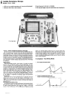
Fig. 1. Model 1743 A is a
general-purpose, dual-channel,
100-MHz oscilloscope that has the
capability of measuring very short
time intervals with 100-ps
resolution. By using a crystalcontrolled oscillator as a time re
ference, and averaging readings,
Model T 743 A provides the most
accurate time-interval measure
ment capability available in real
time oscilloscopes.
11
© Copr. 1949-1998 Hewlett-Packard Co.
technique, has proved to be so effective that it has
been adopted by other oscilloscope manufacturers as
well.
A further increase in the accuracy and ease of mak
ing measurements of very short time intervals has
now been made possible by combining electronic
counter circuits with the dual-delayed sweep. This
technique is used in a new oscilloscope, HP Model
1743 A (Fig. 1), to enable measurements of time inter
vals shorter than 15 /AS with less than 100-ps error.
Measurements of longer time intervals, up to 60 sec
onds, are made with 5-digit resolution and with errors
less than 0.002% of reading ±1 count.
sured. Thus, propagation delay, clock skew, and
other such quantities are readily measured.
The new delta-time technique is so precise that
errors introduced into dual-channel measurements
by inequalities in the signal paths from the test points
through the probe cables, attenuators, and
preamplifiers are perceptible. However, the mag
nitude of these errors is easily determined by connect
ing the oscilloscope's probes to the same test point
and measuring the time delay between like points on
the two waveforms. The result of this measurement
can be used to correct subsequent measurements if a
need exists.
Double Counting
Delta Time
The principle of the new delta-time technique is
illustrated in Fig. 2. Counting begins at the start of a
main sweep and continues to the point in the sweep
indicated by the intensified marker position selected
by the instrument's START control, in this case the
leading edge of the second pulse (Fig. 2a). On the next
sweep, a new count begins at the start of the sweep but
continues to the point selected by the STOP control, in
this case the trailing edge of the same pulse (Fig. 2b).
The digital processing circuits then subtract the first
reading from the second and present the result on the
digital readout, giving pulse width directly.
By positioning the START and STOP markers appro
priately, the user can measure other timing paramet
ers. If in the example above the STOP marker were
placed on the leading edge of the third pulse, the
oscilloscope would give a reading of pulse period.
When the oscilloscope is displaying two
waveforms in the alternate sweep mode, the START
marker appears on the channel A trace and the STOP
marker on channel B. As long as both traces are ini
tiated by the same trigger source, the time delay be
tween selected points on the waveforms can be mea-
The intensified markers are generated by the oscil
loscope's delayed sweep, which must be set to a
sweep time shorter than the main sweep. The CRT
thus shows the time duration of the DELAYED SWEEP as
brightened segments on the displayed waveform (Fig.
3a). To obtain maximum accuracy in delta-time mea
surements , after positioning the markers over the two
points of interest the user switches the instrument to
the A TIME mode, which expands both brightened
segments to full CRT screen width and displays both
simultaneously (Fig. 3b). The numeric readout con
tinues to display the time difference represented by
the starting points of the segments but any two points
on the same vertical axis will have this same time
difference. So, by adjusting the START and STOP con
trols to bring the two points of interest to the same
vertical graticule line, as shown in Fig. 3c, the user
obtains a reading of the time interval between these
points with maximum accuracy.
In addition to being useful for measuring time in
tervals, the delta time technique is also useful for
establishing time intervals. For example, suppose
that on the production line it is necessary to adjust a
delay multivibrator's output to a particular pulse
width. The oscilloscope's controls are adjusted so the
numeric readout displays the desired pulse width.
When the scope probes are connected to the test
points, the test technician may initially be presented a
display like that shown in Fig. 3b, but by adjusting the
multivibrator timing control, he can cause the pulse
leading and trailing edges to intersect at their 50%
levels, as shown in Fig. 3c. The pulse then has the
specified width.
Accuracy
Pulse Width = 72-7!
The accuracy obtainable with the new delta time
technique is illustrated in Fig. 4. As can be seen, a
substantial increase over other oscilloscope
techniques is achieved. This is because the measure
ment is now referenced to a crystal-controlled time
base — sweep linearity no longer affects measurement
Fig. 2. Model 1743 A Oscilloscope alternately measures the
time from the start of the sweep to a point selected by the START
control (a) and to a second point selected by the STOP control
(b). Obtaining the difference between the two readings gives
the time between START and STOP points.
12
© Copr. 1949-1998 Hewlett-Packard Co.
(b)
(Ç)
Fig. 3. START measurements are made with Model 1 743A by first adjusting the START and
STOP start so the brightened segments of the trace span the start and stop points of the
measurement (a), then switching to the A TIME mode to expand both brightened segments to full
screen stop (b). The START and STOP controls are then adjusted so the desired start and stop
points level. on the same vertical graticule line (c), in this case the pulse 50% level.
results. But what about counters? Quality counters do
give higher resolution for longer time intervals and
can have greater time base accuracy. They can also
make measurements on single-shot events and some,
just like the new Model 1743 Oscilloscope, can mea
sure time intervals right down to zero time duration.
Model 1743 A enhances measurement accuracy by
being able to provide a visual indication of where the
start and stop points occur. It can also accommodate a
wider range of input signal amplitudes than most
counters can. Trigger hysteresis errors have been
eliminated by processing the trigger waveform such
that triggers of either polarity have the same polarity
when applied to the trigger-level comparator. In addi
tion, certain inherent measurement errors, such as
delays in opening and closing the counter gate, are
cancelled by the subtraction process used in the new
delta-time measurement technique. Furthermore,
Model 1743 A locks out all of the events capable of
triggering a time-interval measurement except those
selected visually.
Sweep time
0.1 to 0.5
1 to 5 ¿is/div
10 to 50 ¿¿s/div
0.1 to 0.5 ms/div
1 to 5 ms/div
Number of readings Display
averaged resolution
10,000
1000
100
10
Direct
100 ps
1 ns
10 ns
100 ns
1 IJLS
For sweep times of 10 ms/cm and slower, the 100MHz clock is divided down to prevent display over
flow. The following table shows the resolutions ob
tained.
100 r
o 1.0
Conventional
100 MHz Oscilloscope
Conventional
A Time Oscilloscope
Time-Interval Averaging
a 0.1
The time reference in Model 1743A is a 100-MHz
crystal-controlled oscillator that gives a basic resolu
tion of 10 ns in time-interval measurements. How
ever, during measurements of very short time inter
vals, accuracy and resolution are increased by the use
of time-interval averaging, which reduces the ±1count uncertainty inherent in counter measurements
by a factor of V~n^ where n is the number of readings
averaged.2 On the fastest main sweeps (=S0.5 ¿ts/div),
10,000 readings are averaged to give a resolution of
100 ps. On slower sweeps, the number of readings
averaged and the resolution obtained is determined
by the five-digit (plus exponent) display, as listed in
the following table.
0.01
0.001
1 ns
10 ns 100 ns
10 //s
Time Interval
Fig. 4. The accuracy of time-interval measurements made by
Model 1 743A as compared to other oscilloscopes is shown by
these graphs of percent error as a function of time interval
duration.
13
© Copr. 1949-1998 Hewlett-Packard Co.
Sweep time
Display
resolution
10 to 50 ms/div
10 (is
0.1 to 0.5 s/div
100 fj-s
1 and 2 s/div
1 ms
In some cases, it is possible to obtain six-digit re
solution, as explained in the following.
Calibrated Vernier
Because sweep calibration is no longer a factor in
the accuracy of measurements made by the new
delta-time technique, the sweep vernier can be used
to modify the sweep time for the convenience of the
user without affecting accuracy. He can thus use the
vernier to align clock pulses exactly with the
graticule lines or bring an off-screen pulse on screen.
Actually, accuracy can be enhanced since bringing an
off-screen pulse on screen with the vernier means the
user can switch to a faster sweep range to view the
pulse with higher resolution. For example, the older
delta-time technique would require a sweep time of 2
jLts/div to measure the width of a 12 /¿s pulse. With the
new technique, the user can switch to a sweep time of
0.5 ¡jisldiv and use the sweep vernier, which has a 3:1
range, to bring the pulse entirely into view. The pulse
can then be measured with 100-ps resolution.
In some cases using the vernier this way could
result in a display overflow, but the display can ac
commodate a one-decade overflow. It indicates this
by causing a decimal point to appear on each side of
the exponent. If the two decimal points appear when
the user switches to a shorter sweep time and uses
the sweep vernier to encompass the desired portion of
the waveform, he gets a six-digit reading by men
tally inserting a 1 to the left of the most significant
digit.
First-Pulse Measurements
The inevitable ramp nonlinearities at the start of a
sweep do not affect measurement accuracy, just as
sweep calibration is not a factor. Hence, the START
marker can be positioned at the sweep start, allowing
examination of events close to the sweep trigger. This
"first pulse" capability facilitates measurements of
low-repetition-rate events that formerly required very
long sweep times with a consequent loss of measure
ment resolution. The older delta time technique
could not be used for measurements on the event that
triggered the sweep nor could it measure non-cyclic
events, such as software-generated flags, that are
readily measured with the new technique.
Triggered Measurements
Unlike earlier delta-time techniques, the TRIGGER
AFTER DELAY mode can be used with Model 1743 A
when making time-interval measurements. In this
mode, the TRIGGER LEVEL and SLOPE controls are used
to establish the start and stop points of the measure
ment. For example, in making a pulse-width mea
surement, the START marker is set to trigger on a
positive-going slope and the STOP marker on a
negative-going slope. The TRIGGER LEVEL control is
then set at the 50% points (in this mode start and stop
points are always at the same level). To determine
exactly where the trigger level is, the user can switch
to the A TIME (delayed sweep) mode and note where
the two waveforms cross.
The significance of the TRIGGER AFTER DELAY mode
is that once the trigger level has been established, the
Vertical
Amplifier
Chain
IT*
Trigger
Conditioner
START
Fig. 5. Simplified block diagram of the Model 1743 A Oscilloscope.
© Copr. 1949-1998 Hewlett-Packard Co.
the counting circuits interface to the Model 1743A's
oscilloscope circuits. The main-sweep trigger enables
both counters alternately and the delayed sweep trig
ger halts them. However, on one sweep, the delayed
sweep triggers when the main sweep ramp reaches
the level selected by the START control. On the next
sweep, it triggers when the main sweep reaches the
level of the STOP control. The arithmetic unit then
finds the difference between the two counts, averages
the results, and presents the result on the numeric
display.
oscilloscope can be switched to the MAIN SWEEP mode
and maximum accuracy and resolution are still ob
tained with the convenience of having an overall dis
play of the waveform(s), removing any chance of
measurement error because of misplacement of the
START and STOP markers. This mode greatly simplifies
certain measurements. For example, changes in pulse
width as the pulse repetition rate or temperature are
varied can be read directly without readjusting con
trols, since the START and STOP points automatically
track shifts in the leading or trailing edges of the
pulses. It also simplifies circuit adjustments since the
digital display tracks changes in the time interval as
the circuit under test is adjusted. Because the START
and STOP controls need not be adjusted precisely
when using the TRIGGER AFTER DELAY mode, relatively
unskilled personnel can obtain accurate and repeatable measurement using this mode.
Removing Anomalies
Fig. 6 shows how the subtraction process helps to
Clock Burst
Between Main
and Delayed
Gates
A General-Purpose Oscilloscope
The basic oscilloscope circuits in the new Model
1743 A are the same as those in the Model 1740A.3
Both are 100-MHz dual-trace oscilloscopes that have
a third trace for displaying the waveform applied to
the sweep trigger circuit. Vertical deflection factors
range from 5 mV/div to 20 V/div and a x 5 magnifier
gives deflection factors of 1 mV/div to 40 MHz on both
channels. Sweep times range from 50 ns/div to 2 s/div
and a x 10 magnifier extends the fastest sweep to 5
ns/div. With sensitive, stable triggering, precision
time bases, and bright, sharp traces on an 8xlO-cm
display, these are versatile instruments suitable for a
wide variety of uses. The delta-time capability gives
an additional dimension to the Model 1743A.
The simplified block diagram of Fig. 5 shows how
Delayed rSweep
Gate
Alternate
Sweep
Control
of Clock Bursts to
be Averaged
Main
Sweep
Gate (
Main Sweep Gate
Delayed
Sweep
Gate
Burst
Period
v ,
Inhibit
t,-»
Measurement Wanted: T2-T,
Intervals Measured: T1-t1+t2
Ta-ti+tj
Gated Clock
till
After Subtraction: A = T2-ti+t2-(T1-t,+t2) = T2-T
Fig. 7. Measurement-enable circuit generates bursts of clock
pulses that extend from the start of the main sweep to the start
of the delayed sweep. The start of each burst is synchronized
to the clock pulses.
Fig. 6. Propagation delays (t1 and l¿) that could alter mea
surement results are eliminated by the subtraction process.
15
© Copr. 1949-1998 Hewlett-Packard Co.
On Delta-Time Measurements
clock period by only 1 ns in this case. Furthermore, thetriggered
delta-time measurement mode of Model 1743A reduces the
chances for human error, enabling the 1-ns allowance for error
to be easily and consistently met in a production environment.
The role of delta-time measurements in establishing a system
clock rate can be illustrated by a hypothetical example. Let us
assume that we have a system that we wish to operate at a clock
rate of 10 MHz and that it is necessary to partition the 100-ns
clock period so five events can occur in sequence between
clocks. As usual, temperature-compensated one-shot multi
vibrators define the clock period subintervals.
Assume further that the activity that must take place within
each subinterval is analyzed and, using worst-case calcula
tions, it is determined that the minimum time lapse for each
subinterval is 20 ns. We can now construct an error budget
where the uncertainty in establishing the first 20-ns edge is
added to the uncertainty in the second edge, and so on. If a
high-quality analog oscilloscope were to be used to measure
the time intervals as the multivibrators are adjusted, the error
build-up would be:
Clock-to-Edge Instrumentation Time
I n t e r v a l
E r r o r
E r r o r
2
4
6
8
0
n s
 ± 2 . 5 %
0 n s
 ± 1 . 5 %
0 n s
 ± 1 . 0 %
0 n s
 ± 1 . 0 %
Â
Â
Â
Â
±
±
±
±
0
0
0
0
.
.
.
.
5
6
6
8
n
n
n
n
Where Moderate Accuracy is Sufficient
There are many situations where errors of 1% to 3% can be
tolerated in time-interval measurements. One would assume
that a for analog oscilloscope is accurate enough for
these measurements but it is not generally appreciated that
timing accuracy degrades as the measured time interval be
comes a smaller and smaller part of the total sweep width. For
example, 3% accuracy in a measurement of 20 ns degrades to
about 5% at 1 0 ns and 9% at 5 ns. If a sweep time longer than 20
ns/div were required to accommodate all of the data on screen,
measurement errors could be far greater than 10%.
With its "calibrated vernier," Model 1 743A provides an accu
racy of 2% for 5-ns time intervals with sweep times as long as 1 .5
/¿s/div, and 1% for 10-ns intervals.
s
s
s
s
What about Bandwidth?
If the transition times of digital signals are faster than the
response time of an oscilloscope, the oscilloscope will not dis
play the signals with full fidelity. The question is, how will this
affect the accuracies of time-interval measurements?
Analysis (to be published) can show that limited bandwidth
does not affect accuracy as much as one might suppose. The
point is, the transition times of both edges involved in a timeinterval measurement are delayed similarly so, ¡f a measure
ment is made at the 50% level, the time interval is little affected.
A measurement of the propagation delay of a 2-ns ECL transi
tion can be made with the 100-MHz Model 1743A (transition
time 3.5 ns) with no error attributable to bandwidth when the
transition times and slopes of both edges are identical. How
ever, if the transition time of the second edge is slowed, a small
error occurs because the slower edge is not subject to the same
degree of distortion as the faster edge. If the first edge were 2ns
and the second were 10 ns, a 70-ps error would be introduced.
If the slopes of the edges are different, then significantly
greater errors are introduced when measurements are made at
levels other than 50%. Since most device specifications and
pulse width definitions are made at the 50% level, the 100-MHz
Model 1743A is entirely capable of making timing measure
ments with bandwidth errors less than ±1 50 ps in logic families
up to and including ECL 10K.
Cumulative total: ±2.5 ns
This tells us that the system clock period must be extended by
at least 2.5 ns to guarantee that each subinterval is not less than
20 ns in duration.
This analysis was made at the very limits of the oscilloscope's
specified accuracy so, to account for long-term degradation of
the instrument's calibration, we would want to extend the clock
period by 5ns. More likely, to assure an adequate margin for the
measurements in a production environment, we would extend
the clock period 10 ns. Thus, our system would be specified to
operate at a clock rate of about 9 MHz, rather than 10 MHz.
The following table shows the error budget ¡f a Model 1 743A
Oscilloscope were used to establish the subintervals.
Clock-to-Edge
Instrumentation
Time
Interval
Error
Error
20 ns
±0.5%
±0.1 ns
40 ns
±0.2%
±0.8 ns
60 ns
±0.1%
±0.096 ns
80 ns
±0.12%
±0.096 ns
Cumulative total: ±0.372 ns
Because of the long-term stability of the crystal-controlled
time base in Model 1 743A, we would feel safe in extending the
Another potential problem concerns the asyn
chronous nature of the main sweep trigger with re
spect to the crystal-controlled time base. It is quite
possible that this trigger could open the counter gate
in the middle of a clock pulse, making the first pulse
period shorter than those following. Since the coun
ters are edge-triggered, it is important that this first
pulse have the same period as those following to
avoid anomalous counter operation.2
The enable circuit that gates clock pulses to the
counters is shown in Fig. 7 along with a timing dia
gram. This circuit operates as follows. When the in
hibit signal, which suppresses activity for a short
recovery period following a measurement, goes to the
overcome a problem that can occur with conventional
clock-counting time-interval measurements. This
problem concerns errors that can result if propagation
delays in the start and stop channels are different,
which would alter the time difference between start
and stop points.
Referring to Fig. 6, it is desired to measure time in
tervals Ta and T2 and find their difference, but be
cause of propagation delays in the main and delayed
sweep triggers (t1 and 1 2 respectively), the actual
gated counts are equivalent to Tj -- ta + t2 and
T2 — t: + t2. However, as shown in Fig. 6, the sub
traction process eliminates t: and t2 in the results,
leaving T2 - Ta, the quantity desired.
16
© Copr. 1949-1998 Hewlett-Packard Co.
high state, the next rising edge of the alternate sweep
control clocks the Q output of FFl to the low state
(burst enable). When the main sweep gate sub
sequently occurs, the next clock edge clocks the Q
output of FF3 low (burst period) . This first clock pulse
and the following ones are then gated to the counters
until the delayed sweep gate occurs, which sets FF3,
closing the clock pulse gate (the gate could close
during the last pulse but this is of no consequence
since the leading edge has already occurred).
The pulse-burst sequence repeats until a counter
has determined that the necessary number of se
quences have occurred for the averaging process. The
"end-of-average" signal then stores the accumulated
counts, resets the counters, and initiates the inhibit
signal (the setting of the MAIN TIME/DIV range switch
determines the number of pulse bursts to be averaged,
along with the position of the decimal point in the
display and the value of the exponent).
The stored numbers are written into the arithmetic
unit, where their difference is found, and then de
coded and displayed.
ideas were provided by Lab Section Leader Walt
Fischer and Product Managers Dick Stone and Vic
Bunze.Li
References
1. W.A. Fisher and W.B. Risley, "Improved Accuracy and
Convenience in Oscilloscope Timing and Voltage Mea
surements," Hewlett-Packard Journal, December 1974.
2. D.C. Chu, "Time Interval Averaging: Theory, Problems,
and Solutions," Hewlett-Packard Journal, June 1974.
3. A.I. Best, "A 100-MHz Analog Oscilloscope for Digital
Measurements," Hewlett-Packard Journal, December 1975.
Ronald C. Westtund
Ron Wesilund joined HP in 1970,
the same year he graduated from
the University of Utah with a BSEE
degree. He contributed to the
Models 1710A and 1741 A Oscil
loscopes and the 1620A Pattern
Analyzer before undertaking pro
ject leadership of the 1 743A. In lei
sure hours, Ron gets involved in
church activities and he enjoys
playing golf and handball, and
going hunting. He is married and
has one small daughter.
Acknowledgments
Tom Bohley and Al Best contributed to the electri
cal design of Model 1743A. Mechanical design was
by John Campbell and George Blinn. Many helpful
SPECIFICATIONS
Model 1743A Oscilloscope
Horizontal Display Modes
Vertical Display Modes
Channel A; channel B; channels A and B displayed alternately on successive
sweeps blanking or by switching between channels at 250-kHz rale with blanking
during switching (CHOP); channel A plus channel B (algebraic addition); and
trigger view.
Vertical Amplifiers (2)
Bandwidth and Rise Time at all deflection factors (rom 0=0 to +55°C.
BANDWIDTH (3 dB down from 8 div reference signal):
DC-COUPLED: de lo 100 MHz in both SOli and 1 Mil input modes.
AC-COUPLED: approx. 10 Hz to 100 MHz: 1 Hz with 10:1 divider probes.
BANDWIDTH LIMIT: limits upper bandwidth to 20 MHz
RISE TIME: =¿3.5 ns measured from 10% lo 90% points Of 6-div input Step.
DEFLECTION FACTOR
RANGES: 5 mV/div lo 20 V-div in 1, 2, 5 sequence, accurate within 3%.
VERNIER: continuously variable between all ranges; extends maximum deflec
tion factor to at least 50 V/div.
POLARITY: channel B may be inverted by front-panel pushbutton.
DELAY LINE: input signals are delayed sufficiently to view triggering edge of input
ulse.
IN UT COUPLING: selectable AC or DC, 5011 (dc). or ground. Ground position
Ã- isconnects input connector and grounds amplifier input.
IN UT RC (selectable]
C OH DC: 1 MCI ±-2% shunted by approx. 20 pF.
OOHM: 50 11 ±3%.
A B OPERATION
MPLIFIER: bandwidth and deflection factors are unchanged; channel B maybe
inverted for A-B operation.
DIFFERENTIAL (A-B) COMMON MODE; CMRR is at least 20 dB from dc to
20 MHz. one mode signal amplitude equivalent to 8 divisions with one
vernier adjusted for optimum rejection.
VERTICAL MAGNIFICATION <x5)
BANDWIDTH: 3 dB down from 8-div reference Signal.
OC-COUPLED: dc lo approximately 40 MHz.
AC-COUPLED: approximately 10 Hz to 40 MHz.
RISE step). ^s9 ns (measured from 10% to 90% points of 8-div input step).
DEFLECTION FACTOR: increases sensitivity of each deflection factor setting
TRIGGER SOURCE
CHANNEL A: all display modes triggered by channel A signal.
CHANNEL B: all display modes triggered by channel B signal.
COMPOSITE; all display modes triggered by displayed signal except in Chop. In
Chop mode, trigger signal is derived from channel A.
LINE FREQUENCY: ¡rigger signal is derived from powerline frequency.
TRIGGER VIEW: Displays internal or external trigger signal. In Alternate or Chop
mode, channel A, channel B. and trigger signal are displayed. In channel A or
B mode, Trigger View overrides that channel. Iniernal trigger signal amplitude
approximates vertical signal amplitude. Ext. trigger signal defleclion faclor is
approximately 100 mV/div. or 1 V/div in EXT - 1 0. Triggering poinl is approximately
center the With identically timed signals to a vertical input and the Ex!,
trigger input, trigger signal delay is • 3.5 ns.
Main, A time, mixed, mag '10, and A vs B.
MAIN AND DELAYED TIME BASE RANGES:
MAIN: 50 ns/div to 2 s/div in 1, 2, 5 sequence.
DELAYED: 50 ns/div to 20 ms/div in 1, 2. 5 sequence.
ACCURACY, 50 ns/dlv to 20 ms/dlv (add 1% lor 50 ms/div
A c c u r a c y T e m p R a n g e
x1
±3%
0°C to +15°C
•MS'CtO +35°C
-t-35'C to + 55°C
ax tend s
MAIN SWEEP VERNIER: continuously variable between
slowest sweep to at least 5 s/div.
MAGNIFIER (xio): expands all sweeps by factor of 10.
CALIBRATED SWEEP DELAY
DELAY TIME RANGE: 0 to 50*Main Time/Div settings of 100 ns lo 2 s.
DIFFERENTIAL TIME MEASUREMENT
ACCURACY: ±0.002% of reading *1 count from +15°C lo +35°C; rO.005%
of reading ±1 count from 0CC lo +15'C and +35°C to +55°C.
TIME RESOLUTION OF ~^ COUNT:
S w e e p R a n g e s / d i v  ± 1 C o u n t R e a d i n g s
Averaged
0 . 1 Â ¡ i s , 0 . 2 i i S , 0 . 5 / i s r 1 0 0 p s 1 0 0 0 0
j .
••.
Ã-Ã-S,20/¿ . 50-Ai
10
For intervals greater than 0.5 ms. ±1 count becomes insignificant and accuracy
can be considered a percent of reading.
READOUT: 5-digit LED plus exponent.
CRYSTAL AGING: 0.0005% per year.
DELAY JITTER: 0.002% (1 part in 50.000) of maximum delay in each step
from -15°C to +35"C; --0.005% (1 part in 20.000) from O'C to + 15"C and
+ 35'C lo +55'C.
Triggering
MAIN SWEEP
NORMAL; Sweep is triggered by internal or external signal.
AUTOMATIC- bright baseline displayed in absence of input signal. Triggering is
same as Normal above 40 Hz.
SINGLE, sweep occurs once with same triggering as Normal; reset pushbutton
arms sweep and lights indicator.
INTERNAL: dc to 25 MHz on signals causing 0.5 divisions or more vertical de
flection, increasing lo 1.5 division of vertical deflection at 100 MHz in all display
modes 5 signal level is increased by 2 when in Chop mode and by 5
when -5 vertical magnifier ¡s used).
EXTERNAL: dc 10 50 MHz on signals ol 65 mV p-p or more increasing to
150 mV p-p at TOO MHz (required signal level is increased by 2 when m
Chop mode),
17
© Copr. 1949-1998 Hewlett-Packard Co.
DELAYED SWEEP (SWEEP AFTER DELAY)
AUTO: delayed sweep automatically starts at end of delay period.
TRIG: delayed sweep is armed and triggerable at end of delay period,
INTERNAL: dc to 25 MHz on signals causing 1 division or more vertical deflection
to 2 div. at 100 MHz in all display modes (required signal level ¡s increased by
2 when in Chop mode and by 5 when x5 vertical magnifier is used).
EXTERNAL: dc to 50 MHz on signals of 100 mV p-p or more increasing to 200 rnV
p-p at mode). MHz (required signal level is increased by 2 when m Chop mode).
EXTERNAL INPUT RC: approximately 1 Mil shunted by approx. 20 pF.
MAXIMUM EXTERNAL INPUT: 250 V (dc + peak ac) or 500 V p-p ac at 1 kHz
COUPLING: AC, DC, Main LF REJ, or Main HF REJ.
AC: attenuates signals below approx. 20 Hz.
LF REJECT (MAIN SWEEP): attenuates signals below approx. 4 kHz.
HF REJECT (MAIN SWEEP): attenuaies signals above approx. 4 kHz.
TRIGGER HOLDOFF (MAIN SWEEP): increases sweep holdoff time in all raÃanges.
CALIBRATED MIXED TIME BASE
Dual sweep base in which main time base drives first portion of sweep and de
layed operates base completes sweep at faster delayed sweep rate. Also operates
in single sweep mode. Accuracy, add 2% to main time base accuracy.
General
CATHODE-RAY TUBE: Hewlett-Packard. 12.7 cm (5 in.) rectangular CRT, post
accelerator, approximately 15 kV accelerating potential, aluminized P31 phosphor.
Z-AXIS INPUT (INTENSITY MODULATION): +4 V, ^50-ns widlh pulse blanks
trace of any intensity, usable up to 10 MHz for normal intensity. Inpul fl.
1 kil ±10%. Maximum input ±20 V (dc +• peak ac).
REAR of OUTPUTS: mam and delayed gates, 0 V 10 >*2.5 V capable of
supplying approximately 5 mA.
POWER: 100, 120, 220, 240 Vac, ±10%: 48 to 440 Hz; 100 VA max.
WEIGHT: 13kg (28.6 Ib).
DIMENSIONS: 335 mm W x 197 mm H *• 492 mm D (13.2 - 7.75 x 19.4 ¡n.)
ACCESSORIES FURNISHED: blue light filter, front panel cover, power cord,
vinyl Model storage pouch, operator's guide and service manual; two Model
10041A. 1CM divider probes approximately 2 m (6 6 ft) long
OPTIONS
001: fixed power cord in lieu of detachable power cord.
101: interface STATE DISPLAY— single pushbutton (Gold Button) interface option
for operation with HP Model 1607A Logic State Analyzer. Permits single push
button switching between functional. 16-channel logic stale analysis and elec
trical analysis of digital data. Option 1 01 removes the A vs B mode and replaces
it with the State Display pushbutton.
PRICES IN U.S.A.:
MODEL 1743A OSCILLOSCOPE, $3300.
OPT 001. add $15. OPT 101, add $105.
MANUFACTURING DIVISION: COLORADO SPRINGS DIVISION
1900 Garden of the Gods Road
Colorado Springs, Colorado 80907 U.S.A.
A Wide-Ranging, Automatic LCR Meter for
Stand-Alone or Systems Applications
Microprocessor control broadens the capabilities of this
speedy LCR meter and makes it readily adaptable to BCD
or HP-IB automatic systems.
by Masahiro Yokokawa and Keiki Kanafuji
FOR AN ELECTRONIC CIRCUIT to meet perfor
mance goals, the values of the components used
in assembling the circuit must fall within certain
ranges, some wide, some narrow. Despite increasing
sophistication in the design and manufacture of pas
sive circuit components, differences between sup
posedly identical components do exist and the ranges
of values encountered often exceed acceptable limits.
Thus, most electronic laboratories, quality-control
labs, and receiving departments are equipped to mea
sure the actual values of the components with which
they are concerned, a process that is not only time
consuming, but one that often introduces errors of its
own. To speed these measurements, and reduce the
human errors that arise in this activity, late-model
LCR meters, such as the Model 4261A described in a
recent issue of the HP Journal,1 have been designed
with a high degree of automation.
A new LCR meter, Model 4262A, uses a micro
processor to further automate procedures while in
creasing the instrument's capabilities without incur
ring significantly greater costs. To measure the value
of a passive component with this instrument (Fig. 1),
it is only necessary to select the measurement func
tion and loss parameter — i.e., resistance (R), capaci
tance (C), or inductance {L), and dissipation factor (D)
or quality factor (Q) — select the appropriate test fre
o
c
quency, and connect the component to the test termi
nals. The instrument automatically switches to the
correct measurement range, selects the preferred cir
cuit mode, and presents results on the 3J/2 digit dis
plays in about 250 ms without any time-consuming
balancing adjustments. The user, however, can have
full manual control of the instrument at any time
simply by pressing the appropriate front-panel
pushbuttons.
The front-panel control arrangement is similar to
manually controlled instruments (see Fig. 1) speed
ing familiarization with the instrument. As a further
safeguard against the possibility of unintentional
missettings, the RANGE and CIRCUIT MODE functions
automatically revert to AUTO whenever the L, C, or R
function keys are pressed after manual modes have
been in use. Since most measurements made with this
kind of instrument are made on capacitors, when it is
first turned on the new LCR meter automatically sets
itself for the CD mode using a 1-kHz test frequency.
Enhanced Capability
Besides autoranging, self-triggering, and automatic
selection of the appropriate circuit mode (series or
parallel), the microprocessor brings several other
capabilities to the instrument at little cost. Deviation
measurement is one. When the ALCR key is pressed,
OS 0309
nnfi Qo8
18
© Copr. 1949-1998 Hewlett-Packard Co.
Fig. 1. Model 4262A LCR Meter,
shown here with the comparator
option installed, measures the in
ductance (L), capacitance (c¡, re
sistance (R), dissipation factor (D¡,
and quality factor (Q) of compo
nents with 31/2 digit resolution.
Three test frequencies (120 Hz,
1 kHz, and 10 kHz) enable mea
surements of a wide range of
component values.
the measurement value currently on display is stored,
the display resets to zero, and the present measure
ment range is held. The result of the next measure
ment is then displayed as the difference between the
new measurement value and the stored value . Besides
checking device deviations during incoming inspec
tion, this mode is also useful for monitoring the
changes in device performance caused by variations
in temperature or bias voltage.
For go/no-go measurements, a comparator option
provides two pairs of thumbwheel switches on the
front panel, one pair for LCR and one for DQ. Once high
and low limits are established with these switches, a
green light turns on when measured values are within
the selected limits and a red light turns on when they
are outside the limits. Electrical indications are also
provided at a rear-panel connector.
Self test is another capability obtained at low cost
with the microprocessor. At turn on, all LED indi
cators and all segments of the display digits light up
momentarily to verify that all are functioning. Then,
when the SELF TEST button is pressed while the input
terminals are open (if the C measurement function is
selected), or shorted (with the L or R measurement
function), the instrument tests its digital section and
the process amplifier and phase detector/integrator in
the analog section, through five ranges. If all goes
well, the word PASS appears in the LCR window and
the user can be assured that the instrument is func
tioning correctly (this, however, is not a check on the
instrument's accuracy) . If there is a problem, the word
FAIL is displayed, the range is held, and a code
number indicating the location of the problem ap
pears in the DQ window.
Other capabilities that the microprocessor gives the
new LCR meter include low-cost HP interface bus
(HP-IB) and BCD-output options. In earlier LCR me
ters, an HP-IB interface very often cost more than the
instrument itself but because of the microprocessor,
the cost of the HP-IB interface for Model 42 62 A is less
than one-fifth that of earlier interfaces. The new LCR
meter may thus be interfaced readily to a printer for
logging measurement results, or to a desktop com
puter and/or other instruments for programmed
measurements and statistical analyses of measure
ment results.
When the new instrument is equipped with the
HP-IB option, all functions except DC BIAS are pro
grammable through the HP-IB. The current status of
the instrument (FUNCTION, CIRCUIT MODE, AUTORANGE,
etc.) is made visible by illumination of the LED indi
cators in the corresponding front-panel keys.
Fig. 2. Capacitance and inductance ranges over which the
equivalent series resistance (ESR¡ can be measured with the
Model 4262A LCR Meter. The 10-kHz test frequency extends
these ranges by a factor of 10 over those usually found in
meters of this type.
addition to the customary 120-Hz and 1-kHz test fre
quencies. The 10-kHz test frequency extends the
low-end C and L measurement ranges respectively to
10 pF and 10 /¿H full scale, giving the new instrument
the ability to measure components over exceptionally
wide ranges: inductance from 0.01 ¿u,H (the limit of
resolution) to 1999 H, capacitance from 0.01 pF to
19.99 mF, resistance from 1 mil to 19.99 Mil, dissipa
tion factor from 0.001 to 19.9, and quality factor from
0.05 to 1000. With these wide ranges, the instrument
may be used to measure RF coils, dielectric materials,
electrolytes, the internal resistance of batteries, and
the high dissipation factor of delay lines, as well as
Wide-Ranging Measurements
The new instrument has a 10-kHz test frequency in
•Hewlett-Packard's implementation of IEEE Standard 488-1975.
19
© Copr. 1949-1998 Hewlett-Packard Co.
the values of discrete components.
In particular, the new LCR meter can measure the
ESR (equivalent series resistance) of a capacitor to very
low values, a significant measurement if the capacitor
is to be used for bypass applications. With the 10-kHz
test frequency, the reactance of a wide range of
capacitors becomes low enough for the ESR to be a
significant, and measurable, part of the total impe
dance, as plotted in Fig. 2. At 10 kHz, the resolution of
an ESR measurement is 1 mil for capacitors larger
than 10 /J.F. A five-terminal input (two for voltage,
two for current, and one for a guard) is provided to
minimize errors. Internally-generated bias levels of
1.5V, 2.2V and 6V are also provided, primarily for
measurements on electrolytic capacitors.
Small values of capacitance, such as the junction
capacitance of semiconductor devices, can be mea
sured with the low-level (50 mV) test signal level that
is available. Normally, the test signal level is IV rms.
Typical measurement accuracy is 0.2%. On the
low-end ranges, the test-fixture parasitic reactances
can affect the accuracy of the measurement, so frontpanel C and L offset controls are provided to null out
parasitics up to 10 pF and 1 /¿H. The compensation
technique is explained in Fig. 3.
Internal Operations
Model 4262A LCR Meter finds the values of L, c, R,
D, and Q by determining the vector ratio of the voltage
across the device under test (DUT) to the current
flowing through the device, in the same manner as the
Model 4261A LCR Meter.1
A block diagram is shown in Fig. 4. The voltage
across the device is represented by e: in the diagram
and the current by voltage e2, which is proportional to
the current flowing through range resistor RR in
series with the unknown. Op amp A3 assures accu
rate current flow by maintaining the LOW input ter
minal at virtual ground.
The four-phase generator supplies a signal shifted
in precise increments of 90° with respect to its input
for use as a reference by the phase detector. The integ
rator and comparator are part of a dual-slope A-to-D
converter of the type widely used in digital volt
meters.
As an example of how all this fits together, assume
that a capacitor is being measured in the parallelcircuit mode. Voltage ea is applied to the phase detec
tor and voltage e2, shifted 90°, serves as the phase
detector reference. The output of the phase detector
is applied to the integrator, which starts from the zero
R1
To
Measurement
Circuits
Fig. fixture's capacitance circuits neutralize the effect of the test fixture's stray capacitance (C0)
and residual inductance (LJ. Amplifier A1 inverts the test signal; the CZERO ADJUST control allows
adjustment of the current through Ci so it equals and thus cancels the current through C0. Trans
former the supplies a current to amplifier A6 equal to that flowing through the unknown, and the
combination of C2, A7, and R4 shifts the signal 90°. R4 is adjusted so C2R3R4 = L0, cancelling
the effect of L0 at the input to amplifier A5.
20
© Copr. 1949-1998 Hewlett-Packard Co.
Phase Control
Analog Section
, . . . A - t o - D
Timing Conversion
Digital Section
'V* — / Control
Range
Control
Control
Logic
7>
HP-IB
Interface
BCD Output
Logic
Data Bus
Comparator
Control
U7F
To HP-IB
BCD Data
Thumb-Wheel
Switch Unit
Fig. Under micro block diagram of the Model 4262A LCR Meter. Under control of the micro
processor, the circuits find the ratios of the real and imaginary parts of the voltage across the DUT
with respect to the current (or vice versa), from which the device parameters can be derived.
level and charges for a fixed period of time. Voltage
e2 is then applied to the phase detector input and it is
also used as the phase reference but shifted 180° to
give a negative output, which is used to discharge
the integrator.
As shown in the flow chart of Fig. 5, the micro
processor determines the time of discharge by ac
cumulating clock pulses during the discharge in
terval, the end of discharge being indicated by the
comparator when it senses the return to the zero level.
The discharge time is proportional to the quadrature
part of the vector ratio e2le^, which is proportional to
the capacitance.
The counts accumulated during the discharge time
are stored in a register within the microprocessor.
The stored count can be used directly as the displayed
quantity in a capacitance measurement because of the
choice of the range resistor RR and the clock fre
quency (31 kHz), which eliminates the need for any
computation.
Similarly, by suitable choice of el or e2 as the phase
reference, and proper choice of the phase shift, time
periods proportional to the other measurement quan
tities can be obtained.
Digital Design
The microprocessor reads the keyboard, operates
the displays, the comparator and the HP-IB option,
performs the self test, and controls the many opera
tions of the measurement cycle, such as autoranging
and the A-to-D conversion. The various measurement
routines, the comparator algorithm, the self-test prog
ram, and other instrument programs are stored in a
4K-byte ROM. The microprocessor is the same
control-oriented type as that used in the HP Models
3455A and 3437A Digital Voltmeters.2 It uses parallel
architecture to achieve high speed but does not have a
great deal of computation capability. What little
21
© Copr. 1949-1998 Hewlett-Packard Co.
SPECIFICATIONS
HP Model 4262A LCR Meter
C-D and C-Q Measurement
PARAMETERS MEASURED: C-D' or C-Q; L-D or L-Q; R/ESR.
•Loss measurement may be disabled by switch on internal PC board.
DISPLAY: Dual 314 digit displays; maximum reading 1999.
MEASUREMENT CIRCUIT MODES: Series, parallel, auto (automatic selection
of appropriate equivalent circuit mode).
MEASUREMENT TERMINALS: 5 terminal (HCUR, HpOT, LCUR, LPOT,
GUARD).
RANGE MODES:
LCR: Autorange and manual (up-down).
DO: Autorange and manual (step).
MEASUREMENT FREQUENCIES: 120 Hz (100 Hz Optional), 1 kHz, and
10 kHz ±3%.
TRIGGER: Internal, external, or manual.
DEVIATION MEASUREMENT: When ALCR switch is depressed, measurement
value is stored in memory, range is set to "Hold", and display is offset to zero.
Deviation is displayed as difference between stored value and subsequent
measurement data.
OFFSET stray (Front-panel adjustments to compensate for stray
capacitance and residual inductance of test fixtures):
C: Oto 10 pF; L: 0 to 1 ¡M
SELF/TEST INDICATORS: When SELF TEST function is selected, results of
test PASS, displayed in LCR and DQ windows. Results are indicated by PASS,
FAIL1, FAIL 2, or FAIL 3.
DC BIAS:
INTERNAL: 1.5 V, 2.2 V and 6 V ±5%, selectable on front panel.
EXTERNAL: Rear-panel input for external dc bias (0 to +40 V).
ESR MEASUREMENTS: (See Fig. 2, page 19).
3. ±(% of reading + cou
readoul in counts. Accu
when D < 1.999
4 5% - 2 counts at 1 kHz
ACCURACY: (All accuracies apply over temperature range of 23°C±5°C; at
0°C to 55°C, error doubles):
R/ESR- Measurement
L-D and L-Q Measurement
2. ±(% of reading +• counts)
•Measurement range lor ESR is from 1 mil to 19 kil
(typical! These values vary depending on sanes
3. -(5% + 2 counts) on 10.00 Ml) range al
test frequency.
1 . Calculated (rom D value as a reap'ocal number.
2. Typical data, vanes «tin value of D and number
MEASUREMENT TIME (typical): For 1000-count measurement on low-loss
component with range fixed:
1 kHz, 10 kHz: C/L, 220-260 ms. R, 120-160 ms.
120 (100) Hz: C/L, 900 ms. R, 700 ms.
When above: is selected, the following must be added to the above:
1 kHz, 10 kHz: 45 ms/180 ms per range step.
120 (100) Hz: 150 ms/670 ms per range step.
When UNCAL lamp is lit, the faster ranging time is selected.
READING RATE:
INT (Internal trigger): approximately 30 ms between end of one
measurement cycle and start of next.
EXT (External trigger): measurement cycle is initiated by remote
trigger input.
DIMENSIONS: 426 W x 147 H x 345 D mm (16% in x 5% in x 13% in).
WEIGHT: approximately 8 kg (17.5 Ibs).
POWER: 100/120/220 Vac ±10%, 240 Vac +5%-10%; 48-66 Hz, «55 VA
with any option.
OPTIONS:
001: code, BCD output of LCR and DQ data. 1-2-4-8 BCD code, TTL
logic level, "1 " slate positive. Alternate BCD output may be selected by switch
on internal PC board.
004: low Comparator. Compares measured valye with high and low limit
switch settings for both LCR and DQ and provides High, In, Low comparison
outputs. Cannot be used with Option 101. Comparison outputs: visual, relay
contact closure and TTL level output.
010: 100-Hz Test Frequency instead of 120 Hz,
101: HP-IB data output and remote control.
PRICES IN U.S.A.: Model 4262A, $2335. Opt. 001, $240. Opt. 004, $580.
Opt. 010, no charge. Opt. 101, $395.
MANUFACTURING DIVISION: YOKOGAWA-HEWLETT-PACKARD LTD.
9-1, Takakura-cho
Hachioji-shi
Tokyo, 192 Japan
I ±(% ot reading t counts). Lx is inductance read
out in counts. Accuracies in this table apply wnen
D < 1.999.
ACCURACY FOR LARGE D: Typical accuracies for large D (3= 2 on range 10.00):
Circuit Mode
Accuracy
±(% of reading + counts)
Cp Parallel
5% + (2 + 1000/CX) counts
Cs Series
5% + (5 + Cx/500) counts
Lp Parallel
5% + (5 + Lx/500) counts
Ls Series
5% + (3 + 200/LX) counts
Cx is capacitance readout in counts.
Lx is inductance readout in counts.
22
© Copr. 1949-1998 Hewlett-Packard Co.
To Microprocessor
Data Bus
Bus Driver
/Receiver
Turn-On
Initialization
(Go To Fast
Autoranging Cycle)
+5V
To Other ThumbWheel Switches
Contact Outputs
Auto Phase
Adjustment
T
Integrator
Charge
T
Integrator
Discharge
Fig. of Comparator option requires little hardware because of
the capabilities provided by the microprocessor.
arithmetic there is to be done is accomplished mostly
by incrementing or decrementing counts stored in
registers.
The manner in which this microprocessor system
enables operating features to be added at little cost is
illustrated by the comparator option, diagrammed in
Fig. 6. Each digit of each thumbwheel connects to one
of the ten lines of the comparator data bus by means of
a diode. The diode cathodes for each switch are tied in
common to the switch contact. When the front-panel
COMPARATOR ENABLE key is pressed, the microproces
sor initiates a stored program that sequentially
grounds the common contacts of the thumbwheels,
and for each one senses which line of the data bus is
grounded. The comparator settings can thus be stored
for use during subsequent measurement compari
sons. This technique minimizes the amount of
hardware needed to implement the comparator
function.
Accumulate
Clock Pulses
No
Measurement Data
Display
Acknowledgments
Special thanks are due to Hiroshi Sakayori, who
evaluated the 10-kHz C standard, Shigeo Kamiya for
much help, and Dave Okuyama, who developed the
microcomputer cross-assembler to be run on an HP
2100 Computer. Yoshimasa Shibata contributed to
the mechanical design, and industrial design was
done by Kazunori Shibata. Thanks are due R and D
group manager Shiro Kito and marketing manager
Shigeki Mori who provided significant suggestions
and encouragement throughout the project.
Fig. 5. Flow chart of measurement routine.
23
© Copr. 1949-1998 Hewlett-Packard Co.
Fig. 7. Model 4262A LCR Meter,
shown here without options, has a
front panel arrangement that facili
tates manual control when manual
control is preferred to automatic
operation. With the HP-IB option
installed, a/I pushbutton functions
are programmable through the HP
interface bus (all options are field
installable).
References
1. S. Hashimoto and T. Tamamura, "An Automatic WideRange Digital LCR Meter," Hewlett-Packard Journal, Sep
tember 1976.
2. A. Gookin, "A Fast-Reading, High-Resolution Voltmeter
that Calibrates Itself Automatically J.E. McDermid, J.B.
Vyduna, and J.M. Gorin, "A High-Speed System Voltmeter
for Time-Related Measurements," Hewlett-Packard Jour
nal, February 1977.
Masahiro Yokokawa
Masahiro Yokokawa earned a
BSEE degree from Nagoya Uni
versity in 1971 and worked on the
hardware design of computer
peripherals before joining
Yokogawa-Hewlett-Packard in
1973. After developing an HP-IB
coupler for LCR meters, Masahiro
became project leader for Model
4262A, contributing the digital de
sign. In his spare time he enjoys
swimming and traveling and he
likes to listen to jazz.
Hewlett-Packard Company, 1501 Page Mill
Road, Palo Alto, California 94304
HEWLETT-PACKARDJOURNAL
Keiki Kanafuji
Keiki Kanafuji joined YokogawaHewiett-Packard in 1972 shortly
after obtaining a BSEE degree
from the Tokyo Institute of
Technology. Initially he worked on
some investigative projects then
contributed to the design of the
Model 4272A Preset C Meter be
fore undertaking the design of the
analog circuitry in Model 4262A.
Outside of working hours, Keiki re
laxes by playing contract bridge
and listening to music.
Bulk Rate
U.S. Postage
Paid
Hewlett-Packard
Company
DECEMBER 1977 Volume 29 * Number 4
Technical information from the Laboratories of
Hewlett-Packard Company
Hewlett-Packard Central Mailing Department
Van Heuven Goedhartlaan 121
Amstelveen-1 134 The Netherlands
Yokogawa-Hewlett-Packard Ltd , Shlbuya-Ku
Tokyo 151 Japan
Editorial Director • Howard L. Roberts
Managing Editor • Richard P. Dolan
Art Director, Photographer • Arvld A. Danielson
Illustrator • Susan E. Wright
Administrative Services, Typography • Anne S. LoPresti
European Production Manager • Dick Leeksma
[^ I j delete N from /^ old ^~\ P" A r~"*\ r~"*\ |~^ P" O O . To change your address or delete your name from our mailing list please send us your old address label (it peels off).
L. O O Road, Send days. to Hewlett-Packard Journal, 1 501 Page Mill Road, Palo Alto, California 94304 U.S.A. Allow 60 days.
© Copr. 1949-1998 Hewlett-Packard Co.