1
1 Introduction
Section
This manual provides the installation instructions, periodic
maintenance requirements, troubleshooting procedures
and service guides for 30D QFM TMQuick Fork Mount
Push/Pulls. Note that all specifications are shown in US
and (Metric) units where applicable.
1.1 Special Instruction
Definitions
A statement preceded by A WARNING is information
that should be acted upon to prevent bodily injury. A
WARNING is always inside a ruled box.
CAUTION
A statement preceded by CAUTION is information that
should be acted upon to prevent machine damage.
IMPORTANT
A statement preceded by IMPORTANT is information that
possesses special significance.
NOTE
A statement preceded by NOTE is information that is
handy to know and may make your job easier.
2 Installation Instructions
Section
2.1 Truck Requirements
0
A
A
WARNING: The QFM TMPush/Pull must be
mounted on standard forks to support the
load and the attachment.
0 Sideshifter Limitations: To avoid mounting interference, the Sideshifter components and cylinder must
not protrude in front of the carriage fork bars.
0 Fork Specifications: Forks up to 1.8 in. (4.5 cm)
thick and 40-46 in. (101-l 16 cm) long may be used.
Recommended fork length is 42 in. (106 cm) with bottom taper. The forks must be adjustable to 22.5-25.5
in. (57-64 cm) between the inner edges of the forks.
l
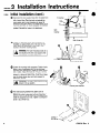
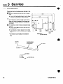
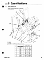
Truck carriage or Sideshifter carriage must conform to
ISO dimensional standard 2328, equivalent to Industrial Truck Association (ITA) dimensions shown at right.
0 Make sure the truck carriage is clean and the notches
are undamaged.
l
In order to conform to industry standard practice, the
hoses should be connected to the truck auxiliary valve
as indicated in the chart at right.
l
Truck Relief Valve Setting: 2300 psi (160 bar),
maximum.
l
Hydraulic flow: 4-10 GPM (15 L/min 38 L/min).
l
Recommended hose and fitting size: No. 6 with minimum fitting orifices of 3/8 in. (9.5 mm).
-f
R
A
WARNING: Rated capacity of the truck /
attachment combination is a responsibility
of the original truck manufacturer and
may be less than that shown on the
attachment nameplate. Consult the truck
nameplate.
iii
14.94 In (379.5 mm)
15.00 in. (381 .O mm)
I
Function, in
sequence of
location to
the operator
Attachment
movement
Motion of the operator’s
hand when actuating the
truck auxiliary control
I
Sideshift
when equipped)
Push/Pull *
678535
Rev. 0
*Trucks equipped with a three-function auxiliary control valve and
solenoid adaption require the control knob electrical button to be
depressed for operation of the push/pull function.
1