Transcript
Manual Operating Instructions
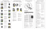
Lift Operating Instructions
Before lift operation, park
on a level surface, away from
vehicular traffic. Place the
vehicle transmission in “Park”
and engage the parking brake.
Vehicle engine must be running.
If your lift does not function as
intended or a visual or audible
warning signal is activated, review
the FMVSS 403/404 Certification
Checklist. Refer to the Manual
Instructions are provided for all
steps that differ from standard
lift operation procedures.
Operating Instructions to manually operate lift. An NL Series lift
is depicted in photos below. Operating procedures are applicable
for other lift models.
Turn wing 1/4 turn.
Manual Operation decal 31412
also provides manual operating instructions (posted on pump cover).
Maintenance and Lubrication
Refer to the Lift Operating Instructions for all normal lift operation procedures. Follow all Lift
Operation Safety Precautions!
Pump
Cover
Lubrication Diagram
Lift-Tite™ Latches
(Tower Pivot Points - 2)
LO
Rotate top clip to access handle.
OPEN DOOR(S) AND SECURE
TO UNFOLD PLATFORM:
Hand
Pump
Handle
Lock
32819
UP
DOWN
32820
A
Hand Pump
D
Release Valve
maximum
30 inch lbs
Valve Tightening
Specification:
Once valve seats
(stops), tighten 15
to 30 inch pounds
as shown.
minimum
15 inch lbs
seats
(stops)
OPEN
OSE
CL
B
OPEN
(Down)
Close
(Up/Stop)
Platform Pivot Pin
Bearings (4)
LO
AI/B.P. Valve
1-30-92
Note: Outer barrier must be fully
unfolded (ramp position) until the
entire wheelchair (or standee) has
crossed the outer barrier. See
Photos E and F.
AI/911/001
11-6-92
E
TO REMOVE PUMP COVER:
F
1. Read Notes below! Load passenger onto platform and lock
wheelchair brakes. See Photo G.
Turn wing nut located on top 1/4 turn
and lift pump cover off. See Photo A.
TO REMOVE PUMP HANDLE:
2. Press UP switch (Photo H) to fold
outer barrier UP fully (vertical
- see Photo I), and raise the platform to floor level. See Photo J.
Release switch.
1. Close hand pump valve (place slotted
end of pump handle onto backup
pump release valve and turn clockwise).
2. Insert handle in pump and stroke
until platform folds fully (stops). See
Photo F.
3. Open hand pump valve (turn counterclockwise) until platform reaches
floor level. Open 1/2 turn only.
4. Close hand pump valve (turn clockwise).
H
Note: Valve must be tight, but do not
overtighten.
DOWN (TO LOWER):
J
3. Unlock wheelchair brakes and
unload passenger from platform.
Place slotted end of pump handle onto
backup pump release valve and turn
counterclockwise (open — 1/2 turn
only) until the platform reaches ground
level and outer barrier unfolds.
I
UP (TO RAISE):
Note: Valve must be tight, but do not
overtighten.
Using hand pump handle (Photo E):
Note: Passenger must be
positioned fully inside yellow
boundries.
2. Insert handle into backup pump and
stroke until platform reaches floor
level (see Photo F).
TO FOLD PLATFORM (IN):
Insert handle into backup pump and
stroke until platform stops (folds fully).
See Photo F.
TO STORE PUMP HANDLE:
1. Insert bottom of handle behind bottom
clip. See Photo B.
2. Rotate top clip to secure (lock)
handle. See Photo C.
TO INSTALL PUMP COVER:
1. Position cover over module back
cover. See Photo G.
2. Align outside cover lip with bottom
cover offset and insert outside cover.
See Photo H.
3. Insert wing stud and rotate 1/4 turn to
lock cover. See Photo I.
LG - Light Grease
TO FOLD PLATFORM:
L
Lock
Lock
Unlock
G
ight Penetrating Oil
L
LPS2, General Purpose
(30 weight or equivalent)
Penetrating Oil
Stainless Stick
Door-Ease
Style (tube)
Stick (tube)
Light Grease
Lubriplate
(Multipurpose)
Available
Amount
Braun
Part No.
11 oz.
Aerosol Can
1.68 oz.
NL917-B5-003.ai
The maintenance and lubrication procedures specified in this schedule must be performed by a Braun
authorized service representative at the scheduled
intervals according to the number of cycles.
Braun dual parallel arm lifts are equipped with hardened pins and self-lubricating bushings to decrease
wear, provide smooth operation and extend the
service life of the lift.
When servicing the lift at the recommended intervals, inspection and lubrication procedures specified
in the previous sections should be repeated. Clean
components and the surrounding area before applying lubricants. LPS2 General Purpose Penetrating
Oil is recommended where Light Oil is called out.
Use of improper lubricants can attract dirt or other
contaminants which could result in wear or damage
to the components. Platform components exposed
to contaminants when lowered to the ground may
require extra attention.
Lift components requiring grease are lubricated during assembly procedures. When these components
are replaced, grease must be applied during installation procedures. Specified lubricants are available
from The Braun Corporation (part numbers provided
above).
All listed inspection, lubrication and maintenance
750
Cycles
Press FOLD (In) switch until
platform stops (fully folded). See
Photos K and L. Release switch.
CLOSE DOOR(S)
Specified (recommended)
Lubricant
Proper maintenance is necessary to ensure safe,
troublefree operation. Inspecting the lift for any
wear, damage or other abnormal conditions should
be a part of the transit agency daily service program.
Simple inspections can detect potential problems.
Position cover over red light.
Align and insert bottom of cover.
K
DE - Door-Ease
Outer Barrier
Lever Bearings
LO
1500
Cycles
15807
15806
14 oz.
Can
15805
Maintenance and Lubrication Schedule
1. Place slotted end of pump handle
onto backup pump release valve and
turn clockwise to close securely.
See Photo E.
TO UNFOLD PLATFORM (OUT):
G
LO - Light Oil
Stroking
Hand
Pump
Using hand pump handle:
Rotate top clip to remove pump handle.
See Photos B and C.
Note: Outer barrier must be fully
unfolded (ramp position) until the
entire wheelchair (or standee) has
crossed the outer barrier. See
Photos E and F.
Type
Outer Barrier
Lever Guide Slot
(Both Sides)
LG
Outer Barrier
Latch Slot
(Both Sides)
LG
F
Note: Inner roll stop and outer barrier automatically function during manual operations.
D
Outer Barrier
Latch Pivot
LO
Lift-Tite™ Latch Rollers (2)
LO
Lubricant
3. Unlock wheelchair brakes and
unload passenger from platform.
Outer Barrier
Pivot Bearings (2)
LO
Lower Fold Arm
Bearings (8)
LO
OSE
CL
Open
Upper Fold Arm
Cam Followers (4)
LO
Saddle Support
Bearings (8)
LO
Upper/Lower Fold Arm
Contact Area (2)
LG
Release Valve
A
I/
10 211
-5 /0
-9 16
2
2. Press DOWN switch until the entire
platform reaches ground level (see
Photo B) and the outer barrier
unfolds fully (ramp position). See
Photo C. Release switch.
Note: Close backup pump release valve
securely before operating electric pump.
Inner Roll Stop
Lever Bearings (2)
and Slots (2)
LO
Inner Roll Stop
Pivot Bearings (2)
LO
Saddle Bearing
Buttons (2)
DE
approximate
1/16" intervals
Note: Outer Barrier must be UP.
TO LOAD PASSENGER:
Inspect lift for wear, damage or any abnormal
condition
Correct as needed.
Inspect lift for rattles
Correct as needed.
Adjust fold pressure and outer barrier fold pressure (if applicable).
See applicable service manual.
Verify FMVSS 403/404 Certification Checklist
See FMVSS 403/404 Certification Checklist
Perform all procedures listed in previous section also
Handrail Pivot Pin
Bearings (4)
LO
C
B
1. Read Note below! Load passenger onto platform and lock
wheelchair brakes.
E
Correct or replace damaged parts and/or
relubricate. See Lubrication Diagram
Upper/lower fold arms (2)
Apply grease (synthetic) to contact areas
between upper/lower fold arms. See Lubrication Diagram
Platform pivot pin bearings (4)
Lower fold arm bearings (8)
Apply Light Oil - See Lubrication Diagram
Inner roll stop pivot bearings (2)
Apply Light Oil - See Lubrication Diagram
Inner roll stop lever bearings (2)
Apply Light Oil - See Lubrication Diagram
Inner roll stop lever slot (2)
Saddle support bearings (8)
Apply Light Oil - See Lubrication Diagram
Apply Light Oil - See Lubrication Diagram
Upper fold arm cam followers (4)
Apply Light Oil - See Lubrication Diagram
Parallel arm pivot pin bearings (16)
Apply Light Oil - See Lubrication Diagram
Handrail pivot pin bearings (4)
Apply Light Oil - See Lubrication Diagram
Hydraulic cylinder pivot bushings (8)
Apply Light Oil - See Lubrication Diagram
Outer barrier lever guide slot
Apply Light Grease to both sides of slot.
See Lubrication Diagram
Inspect Lift-Tite™ latch rollers for wear or damage,
positive securement and proper operation (2)
Correct, replace damaged parts and/or
relubricate.
Inspect inner roll stop for:
• Wear or damage
• Proper operation. Roll stop should just rest on top
surface of the threshold plate.
• Positive securement (both ends)
Resecure, replace or correct as needed. See
Platform Angle Instructions and Platform Floor
Level Adjustment.
Inspect handrail components for wear or damage,
and for proper operation
Replace damaged parts.
Inspect microswitches for securement and proper
adjustment.
Make sure lift operates smoothly
Resecure, replace or adjust as needed. See
Microswitch Adjustment Instructions.
Inspect external snap rings:
• Lower fold arm (6)
• Lift-Tite™ latch roller (2)
• Lift-Tite™ latch gas (dampening) spring (4)
• Upper fold arm cam followers (4)
• Outer barrier hydraulic cylinder mounting pin (2)
• Inner roll stop lever bracket pins (2)
Resecure or replace if needed.
Inspect inner roll stop locks (2) and torson springs
(2) for wear or damage and for proper operation.
Replace damaged parts. Apply Light Oil to inner
roll stop lock pivot point.
Inspect lower fold arm pins (2), axles (2) and
bearings (8) for wear or damage and positive
securement
Replace damaged parts and resecure as
needed. Apply Light Oil.
Remove pump module cover and inspect:
• Hydraulic hoses, fittings and connections for
wear or leaks
• Harness cables, wires, terminals and connections for securement or damage
• Control board, circuit breaker, power switch
and lights for securement or damage
Resecure, replace or correct as needed.
®
Unlock
TO UNLOAD PASSENGER:
C
750
Cycles
Inspect outer barrier latch for proper operation,
positive securement, and detached or missing
spring
D
UNFOL
FOLD
Note: In event platform does
not unfold, press FOLD switch to
release Lift-Tite™ latches.
A
Lift-Tite Latch Dampening Spring
(2 springs - 4 Points)
LO
Hydraulic Cylinder
Pivot Bushings (8)
LO
Saddle
Bearing (1)
DE
Parallel Arm
Pivot Pin Bearings (16)
LO
Parallel Arm
Pivot Pin Bearings (16)
LO
Stand clear and press the UNFOLD switch until the platform
stops (reaches floor level - unfolds
fully). Release switch.
Maintenance and Lubrication
H
Unlock
I
procedures should be
repeated at 750 cycle intervals following the scheduled
4500 cycle maintenance
procedures. These intervals are a general guideline
for scheduling maintenance
procedures and will vary
according to lift use and
conditions. Lifts exposed to
severe conditions (weather,
environment, contamination, heavy usage, etc.)
may require inspection and
maintenance procedures
to be performed more often
than specified.
WARNING
Maintenance and
lubrication procedures
must be performed as
specified by an
authorized service
technician. Failure to
do so may result in
serious bodily injury
and/or property
damage.
Realign towers and vertical arms. Lubricate or
correct as needed.
Perform all procedures listed in previous section also
Maintenance Indicator: The Lift Ready green LED
mounted on top of the pump cover will begin to blink
after every 750 cycles. The blinking LED will not affect
the functions of the lift, but is a reminder to complete
necessary maintenance and lubrication.
Once the lift has been serviced, fully stow the lift. Once
stowed, press the UP button on the hand pendant and
the Floor Level Set button on the back side of the pump
cover until the Lift Ready green LED stops blinking.
Discontinue lift use immediately if maintenance and
lubrication procedures are not properly performed, or if
there is any sign of wear, damage or improper operation.
Contact your sales representative or call The Braun
Corporation at 1-800-THE LIFT®. One of our national
Product Support representatives will direct you to an
authorized service technician who will inspect your lift.
Apply Light Oil - See Lubrication Diagram
Inspect cotter pins on platform pivot pin (2)
Resecure, replace or correct as needed
Hydraulic Fluid (Pump) - Check level. Note: Fluid
should be changed if there is visible contamination. Inspect the hydraulic system (cylinder, hoses,
fittings, seals, etc.) for leaks if fluid level is low.
Use Braun 32840-QT hydraulic fluid (Exxon®
Univis HVI 26). Do not mix with Dextron III or
other hydraulic fluids. Check fluid level with platform lowered fully. Fill to maximum fluid level
indicated on reservoir (specified on decal). Do not
overfill. If fluid level decal is not present - measure 1-3/8" from the fill port to locate fluid level.
Inspect cylinders, fittings and hydraulic connections for wear, damage or leaks
Tighten, repair or replace if needed.
Inspect outer barrier cylinder hose assembly
(hose, fasteners, connections, etc.) for wear, damage or leakage
4500
Cycles
Tighten, repair or replace if needed.
Inspect parallel arms, bearings and pivot pins for
visible wear or damage
Replace if needed.
Inspect parallel arm pivot pin mounting bolts (8)
Tighten or replace if needed.
Inspect platform pivot pins, bearings and vertical
arms for wear, damage and positive securement
Replace damaged parts and resecure as needed.
Apply Light Grease during reassembly procedures.
Inspect upper/lower fold arms, saddle, saddle
support and associated pivot pins and bearings for
visible wear or damage
Replace if needed.
Outer barrier pivot points (2)
Apply Light Oil - See Lubrication Diagram
Outer barrier latch pivot point
Apply Light Oil - See Lubrication Diagram
Inspect gas springs (cylinders) for wear or damage, proper operation and positive securement.
Tighten, replace or correct as needed
Outer barrier latch slot
Apply Light Grease to both sides of slot.
See Lubrication diagram
Inspect saddle bearing (1) and saddle bearing
buttons (2)
Apply Door-Ease or replace if needed. See Lubrication Diagram.
Outer barrier lever bearings (2)
Lift-Tite™ latches (tower pivot points - 2)
Apply Light Oil - See Lubrication Diagram
Apply Light Oil - See Lubrication Diagram
Inspect vertical arm plastic covers Resecure or replace if needed.
Resecure, repair or replace if needed.
Lift-Tite™ latch gas (dampening) spring pivot
points (2 springs - 4 points)
Apply Light Oil - See Lubrication Diagram
Inspect power cable
Mounting
Inspect Lift-Tite™ latches and gas springs for wear
or damage (bent, deformed or misaligned), positive securement (external snap rings) and proper
operation Resecure, replace damaged parts or otherwise
correct as needed. Note: Apply Light Grease to
Lift-Tite™ latch tower pivot point if replacing latch.
Decals and Antiskid
Replace decals if worn, missing or illegible. Replace antiskid if worn or missing.
Inspect outer barrier for proper operation
Correct or replace damaged parts.
Consecutive
750 Cycle
Intervals
Repeat all previously listed inspection, lubrication and maintenance procedures at 750 cycle
intervals.
Check to see that the lift is securely anchored to
the vehicle and there are no loose bolts, broken
welds, or stress fractures.