1
User’s
Manual
Model US1000
Digital Indicating Controller
IM 5D1A01-01E
IM 5D1A01-01E
Yokogawa Electric Corporation
5th Edition
Introduction
This instruction manual describes the general operation of the US1000 Digital Indicating Controller.
■ Intended Readers
This manual is intended for personnel in charge of the following:
·
·
·
·
Installation and wiring
Instrumentation and setup of the controller
Operation and monitoring of the controller
Maintenance of equipment
■ Related Documents
The following documents all relate to the US1000 Digital Indicating Controller. Read them as necessary. The codes enclosed in parentheses are the document numbers.
• US1000 Digital Indicating Controller Functions
Provides detailed descriptions of US1000 functions.
(IM 5D1A01-02E)
• US1000 Digital Indicating Controller Communication Functions
(IM 5D1A01-10E)
Manual for using the US1000 communication function. Supplied with models having the optional
communication function.
• LL1100 PC-Based Parameters Setting Tool
(IM 5G1A01-01E)
Manual for setting US1000 parameters from a personal computer. Supplied with the LL1100 PCBased Parameters Setting Tool.
• LL1200 PC-based Custom Computation Building Tool
(IM 5G1A11-01E)
Operation manual for creating custom computations of the US1000 controller. This manual also
describes examples of custom computations. The LL1200 PC-based Custom Computation Building
Tool includes the LL1100 PC- based Parameters Setting Tool.
• LL1200 PC-based Custom Computation Building Tool Reference (IM 5G1A11-02E)
This is the functions manual necessary for creating custom computations of the US1000 controller.
This manual should be referred to in order to find out and understand what functions offered by the
LL1200.
FD No. IM 5D1A01-01E
5th Edition: May. 2005 (KP)
All Rights Reserved. Copyright © 1998. Yokogawa Electric Corporation
IM 5D1A01-01E
i
Checking Package Contents
Visually check the product for any damage upon delivery.
Keep the box and inner packaging that the product was delivered in, as you will need them if you
have to send the controller back for repair.
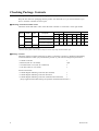
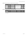
■ Checking of Model and Suffix Codes
Check the model and suffix codes of the delivered controller to ensure that it is the right model.
Option
Codes
Analog input
Analog output
Contact
Model
Suffix
Codes
US1000
-00
Basic type
1
1
1
1
1
0
2
3
-11
Enhanced type
(with custom computation)
2
1
2
2
1
2
7
7
-21
Position proportional type
(with custom computation)
2
1
2
1
1
*2
7
7
/A10
Description
Universal Voltage LPS Current Voltage Relay
Input Output
RS-485 communication
LPS: Loop power supply for transmitter
* The two contact points in the US1000-21 relay item are the relay output and the feedback input.
■ Package Contents
Check the package contents against the list below. If anything is missing or damaged, immediately
contact the dealer at which you purchased the product or your nearest Yokogawa representative.
•
•
•
•
US1000 controller
Brackets (Part No. T9115NK)
Terminal board cover (Part No. L4001DA)
Unit label (Part No. T9115VE)
1
1 pair
1
1
Instruction manuals
• US1000 Digital Indicating Controller (this manual)
1
• US1000 Digital Indicating Controller Functions
1
• US1000 Digital Indicating Controller Communication Functions
1
(Only supplied with models having the optional communication function.)
ii
IM 5D1A01-01E
Documentation Conventions
■ Symbols
The following symbols are used in this manual.
WARNING
Indicates that operating the hardware or software in a particular manner may damage it or result in a
system failure.
NOTE
Draws attention to information that is essential for understanding the operation and/or features of the
product.
TIP
Gives additional information to complement the present topic and/or describe terms specific to this
document.
See Also
Gives reference locations for further information on the topic.
■ Description of Displays
Some of the representations of product displays shown in this manual may be exaggerated, simplified,
or partially omitted for reasons of convenience when explaining them.
IM 5D1A01-01E
iii
Notice
■ This Instruction Manual
(1) This manual should be passed on to the end user. Keep at least one extra copy of the manual in a
safe place.
(2) Read this manual carefully to gain a thorough understanding of how to operate this product before
you start using it.
(3) This manual is intended to describe the functions of this product. Yokogawa Electric Corporation
(hereinafter simply referred to as Yokogawa) does not guarantee that these functions are suited to
the particular purpose of the user.
(4) Under absolutely no circumstances may the contents of this manual, in part or in whole, be
transcribed or copied without permission.
(5) The contents of this manual are subject to change without prior notice.
(6) Every effort has been made to ensure accuracy in the preparation of this manual. Should any
errors or omissions come to your attention however, please contact your nearest Yokogawa
representative or our sales office.
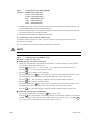
■ Protection, Safety, and Prohibition Against Unauthorized Modification
(1) In order to protect the product and the system controlled by it against damage and ensure its safe
use, make certain that all of the instructions and precautions relating to safety contained in this
document are strictly adhered to. Yokogawa does not guarantee safety if products are not handled
according to these instructions.
(2) The following safety symbols are used on the product and in this manual.
CAUTION
If this symbol is indicated on the product, the operator should refer to the explanation
given in the instruction manual in order to avoid personal injury or death to either
themselves or other personnel, and/or damage to the instrument. The manual describes
that the operator should exercise special care to avoid shock or other dangers that may
result in injury or loss of life.
Protective ground terminal:
This symbol indicates that the terminal must be connected to ground prior to operating
the equipment.
Function ground terminal:
This symbol indicates that the terminal must be connected to ground prior to operating
the equipment.
Alternating current.
(3) If protection/safety circuits are to be used for the product or the system controlled by it, they
should be externally installed on the product.
(4) When you replace the parts or consumables of the product, only use those specified by Yokogawa.
(5) Do not modify the product.
iv
IM 5D1A01-01E
(6) This product has been approved as flameproof electrical equipment for use in a hazardous area,
and hence usable in explosive atmospheres. However, when using this product in a hazardous
area, abide by the conditions in the following standards:
• CSA standard (CSA C22.2 No. 213)
Location Class I, Division 2, Groups A, B, C & D
Temperature Code T4
Note: For the installation procedure, see page App. 6-1.
• FM standard (FM 3611)
Location Class I, Division 2, Groups A, B, C & D
Class I, Zone 2, Group IIC
Temperature Code T4
Note: For the installation procedure, see page App. 6-2.
(7) The suitability of the final installation is to be determined by the local authorities having jurisdiction.
■ Force Majeure
(1) Yokogawa does not make any warranties regarding the product except those mentioned in the
WARRANTY that is provided separately.
(2) Yokogawa assumes no liability to any party for any loss or damage, direct or indirect, caused by
the use or any unpredictable defect of the product.
WARNING
Do not change the setting of the following US1000 controller parameter.
[Setup parameter] - [Main menu: USMD] - [Submenu: Test]
Parameter: TST (Test mode)
This parameter is used to adjust a US1000 controller at the factory. If you change the setting of this
parameter, the US1000 controller may not operate normally.
NOTE
Only personnel with an understanding of the US1000 controller and custom computation fucntions are
qualified to change the settings of the following parameters as necessary. Those using the US1000
controller for the first time and those not knowledgeable about the custom computation function,
should use the default values of the following parameters assigned to the controller.
[Setup parameter] - [Main menu: CONF] - [Submenu: DO and DI]
All the parameters under the submenus above.
If you change the settings of these parameters, some of the fuctions assigned to each US1000 controller mode (US mode) may not work.
IM 5D1A01-01E
v
Contents
Introduction ........................................................................................................................... i
Checking Package Contents ............................................................................................... ii
Documentation Conventions .............................................................................................. iii
Notice.................................................................................................................................... iv
1. US1000 Digital Indicating Controller ...................................................................... 1-1
1.1
1.2
1.3
1.4
1.5
1.6
What is on the Front Panel? ...........................................................................
Characters and Symbols on Digital Displays .................................................
Operation Display and Parameter Setting Display .........................................
Preparing for Operation ..................................................................................
Factory-Set Defaults ........................................................................................
Label Positions ................................................................................................
1-2
1-3
1-4
1-5
1-6
1-7
2. Installing US1000 Controller .................................................................................... 2-1
2.1
2.2
External Dimensions and Panel Dimensions .................................................. 2-2
Mounting the Controller ................................................................................. 2-3
3. Wiring ....................................................................................................................... 3-1
3.1
Procedure for Wiring ...................................................................................... 3-1
3.1.1 Cables and Terminals ............................................................................... 3-1
3.1.2 Direction of wiring .................................................................................. 3-2
3.1.3 Preventing Noise ...................................................................................... 3-2
3.1.4 Terminal Designation ............................................................................... 3-3
3.1.5 Wiring for Power Supply and Transmitter’s Loop Power Supply ........... 3-4
3.1.6 Attaching the Terminal Cover .................................................................. 3-5
3.2 Signals Assigned to Terminals ....................................................................... 3-6
3.2.1 Terminal Assignment for US1000-00 (Basic Type) ................................. 3-7
3.2.2 Terminal Assignment for US1000-11 (Enhanced Type) .......................... 3-8
3.2.3 Terminal Assignment for US1000-21 (Position Proportional Type) ..... 3-20
4. Setting the Basic Functions ....................................................................................... 4-1
4.1
4.2
4.3
4.4
4.5
4.6
4.7
4.8
4.9
Example of Parameter Display ....................................................................... 4-2
Procedure for Setting the Basic Functions ..................................................... 4-3
Selecting the Controller Mode (US Mode) .................................................... 4-4
Selecting the PV Input Type ........................................................................... 4-6
Selecting the Control Computation and Output Types .................................. 4-9
Writing the Data Defined So Far (Parameter Initialization) ........................ 4-11
Defining the Alarm Outputs (as necessary) ................................................. 4-12
Setting the Target Setpoint, Alarm Setpoints, and PID Parameters ............ 4-15
Setting Other Functions (as necessary) ........................................................ 4-17
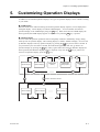
5. Customizing Operation Displays .............................................................................. 5-1
5.1
5.2
5.3
vi
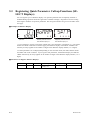
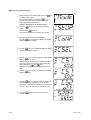
Registering Auxiliary Operation Displays (USER Displays) ........................ 5-2
Displaying the Alarm Status ........................................................................... 5-5
Registering Quick Parameter Call-up Functions (SELECT Displays) .......... 5-6
IM 5D1A01-01E
6. Operation .................................................................................................................... 6-1
6.1
6.2
6.3
6.4
6.5
6.6
6.7
6.8
6.9
6.10
6.11
6.12
6.13
6.14
Switching the Operation Mode ....................................................................... 6-2
Changing the Target Setpoint (SV) ................................................................ 6-3
Manipulating MV ............................................................................................ 6-4
Operations on Single-Loop Type of Controller ............................................. 6-5
Operations on Cascade Type of Controller .................................................... 6-6
Switching Between Cascade Open and Close ................................................ 6-8
Operations on Dual-loop Type of Controller ................................................. 6-9
Display and Operations during Heating/Cooling Computation ................... 6-11
Operation Mode Switching Using Contact Input ......................................... 6-12
Starting Controller Operation ....................................................................... 6-13
Auto-tuning ................................................................................................... 6-14
Manual Tuning .............................................................................................. 6-16
Stopping Controller Operation ...................................................................... 6-17
Power Failure during Operation ................................................................... 6-18
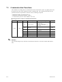
7. Other Functions.......................................................................................................... 7-1
7.1
7.2
7.3
Communication Functions .............................................................................. 7-2
Custom Computation ...................................................................................... 7-3
D Register and I Relay .................................................................................... 7-4
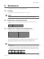
8. Maintenance ................................................................................................................ 8-1
8.1
8.2
8.3
8.4
8.5
Cleaning ...........................................................................................................
Replacement of Mounting Bracket .................................................................
Limited Life Components and Maintenance ..................................................
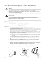
Procedure for Replacing Control Output Relays ............................................
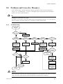
Problems and Corrective Measures ................................................................
8.5.1 Troubleshooting .......................................................................................
8.5.2 Error Code Description ............................................................................
8-1
8-1
8-1
8-2
8-3
8-3
8-4
Appendix 1 Hardware Specifications ................................................................... App. 1-1
Appendix 2 Engineering Units Available for the US1000 ................................. App. 2-1
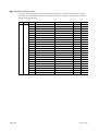
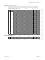
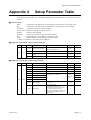
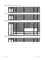
Appendix 3 Operation Parameter Table ............................................................. App. 3-1
Appendix 4 Setup Parameter Table ..................................................................... App. 4-1
Appendix 5 Parameter Map .................................................................................. App. 5-1
Appendix 6 Conditions of Use in Hazardous Areas ........................................... App. 5-1
6.1
6.2
CSA standard ......................................................................................... App. 5-1
FM standard ........................................................................................... App. 5-3
Index ...................................................................................................................................... 1
Revision Record ........................................................................................................... Rev.-i
IM 5D1A01-01E
vii
Blank Page
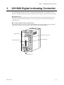
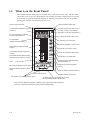
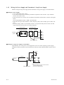
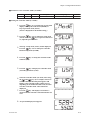
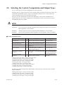
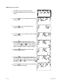
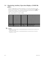
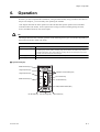
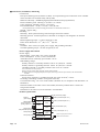
Chapter 1 US1000 Digital Indicating Controller
1.
US1000 Digital Indicating Controller
The US1000 digital indicating controller is designed with sophisticated, yet user-friendly control
functions. The displays and operation keys on the front panel provide for smooth and secure operation.
● Simplified setup
The typical setup of the US1000’s basic control function and the I/O terminal assignment are registered as the “controller mode (US mode).” Users can easily setup the controller by selecting this
controller mode.
● A wealth of displays and operating functions
The US1000 controller has two easy-to-read digital displays and three bar graphs as analog displays.
The operation mode is switched and MV output modified using the dedicated keys.
PV
ALM
LP2
Digital displays
SV
Operation mode keys
MV
100
SV setting keys
Analog bar displays
SET/ENT
0
C
DISP
O
MV operation keys
IM 5D1A01-01E
1-1
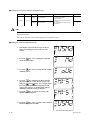
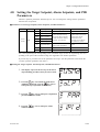
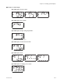
1.1
What is on the Front Panel?
The US1000 controller displays process variables (PV), target setpoint values (SV), and MV output
values (MV) in two ways: on a digital display and an analog bar display. Separate keys are provided
for switching the operation mode and changing SV and MV, thus operators will have no problems
operating the controller from the first time they use it.
Overflow indicator (Yellow LED)
Space for tag number lable
PV digital display (Indicates the process
variable.*1)
MV lamp (Lit while MV is indicated
on the SV digital display.*1)
ALM lamp (Lit when any alarm occurs.)
PV
LP2 lamp (Lit when Loop-2 data are
displayed or in the open cascade status.)
ALM
LP2
SV
C mode key (Changes to CAS mode.)
MV
100
SV digital display
(Indicates the target setpoint.*1)
C mode lamp (Lit in CAS mode.)
A mode key (Changes to AUTO mode.)
SV bar display (Displays the target
setpoint.)
A mode lamp (Lit in AUTO mode.)
PV bar display (Displays the process
variable.)
SET/ENT
Light-loader interface (Used for setting
parameters from a personal computer.)
M mode lamp (Lit in MAN mode.)
DISP
0
Scale
M mode key (Changes to MAN mode.)
O
C
SV setting keys (Increases/decreases
the target setpoint.*1)
SET/ENT key (Used for parameter
setting.)
MV bar display (Displays the MV output.)
Overflow/underflow indicators (Yellow
LEDs)
DISP key (Switches operation displays.)
Internal unit fixing screw
MV operation keys (Changes the MV output.)
Underflow indicator (Yellow LED)
MV fast-change key*2 (Accelerates MV changing
when pressed with the MV operation key.)
*1 This function is valid during operation. A different function is given when setting parameters.
*2 This key is invalid with the US1000-21 model (position proportional type).
1-2
IM 5D1A01-01E
Chapter 1 US1000 Digital Indicating Controller
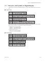
1.2
Characters and Symbols on Digital Displays
The meanings of characters and symbols that appear on the PV and SV digital displays are explained
here.
■ PV Digital Display
Meaning
0 1 2 3 4 5 6 7 8 9
Display
Meaning
A B C D E F G H I J K L M N O P
Display
Meaning
Q R S T U V W X Y Z
Display
Meaning
-
c
-1 /
_
< >
° C
° F Layer*1 Layer*2
Display
During parameter setting, one of the horizontal bar is displayed in the left-most digit of the PV digital
display. Each bar indicates a different level of setting, as outlined below.
*1 Main menu : The upper bar flashes.
Submenu : The middle bar flashes.
Parameter : The lower bar flashes.
*2 When no submenu exists.
Main menu : The upper bar flashes.
Parameter : The lower bar flashes.
■ SV Digital Display
Meaning
0 1 2 3 4 5 6 7 8 9
Display
Meaning
A B C D E F G H I J K L M N O P
Display
Meaning
Q R S T U V W Y Z
Display
Meaning
-
c
-1 / _
° C ° F
Display
IM 5D1A01-01E
1-3
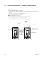
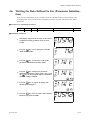
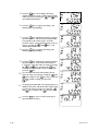
1.3
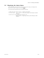
Operation Display and Parameter Setting Display
The US1000 controller shows different types of displays during operation and parameter setting. The
functions given to the keys are also different between the two situations.
● Display during operation
• The PV digital display indicates the PV value.
• The SV digital display usually indicates the SV value, but indicates the MV value when the MV
lamp is lit.
• The SV keys are used to increase and decrease the SV value.
• The analog bar graphs show PV, SV, and MV.
● Display during parameter setting
• The PV digital display indicates the parameter menu or parameter name.
• The SV digital display indicates the set data of a parameter.
• The SV keys are used to increase and decrease the set data of a parameter.
• The analog bar graphs remain the same as they were during operation.
To change from operation to parameter setting, press the
key for 3 to 6 seconds (this period of
time is described as just “for 3 seconds” hereafter). To change from the parameter setting display back
to the operation display, press the DISP key.
SET/ENT
Indicates a parameter menu or parameter name.
PV
PV
PV
ALM
LP2
ALM
LP2
SV
SV or MV
Indicates the set data.
(No display for menu.)
SV
Press for 3 seconds.
MV
100
MV
100
SET/ENT
Data setting keys
SV setting keys
DISP
SET/ENT
0
C
DISP
O
Display during operation
1-4
SET/ENT
0
C
DISP
O
Initial display for parameter setting
IM 5D1A01-01E
Chapter 1 US1000 Digital Indicating Controller
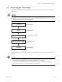
1.4
Preparing for Operation
The US1000 controller must be set up before it can be operated. Set up the controller in the sequence
shown below.
NOTE
The US1000 controller has no power switch. It starts operating and its control action as soon as it is
plugged in, i.e., connected to its power source. Thus, the controller output should not be connected to
the controlled equipment until just before operation.
Installation
See chapter 2
Wiring
See chapter 3
Setup of controller functions
Setting the target setpoint
Operation
See sections 4.1 to 4.7
See section 4.8
See chapter 6
Also read section 4.9, “Setting Other Functions,” and chapter 5, “Customizing Operation Displays” as
necessary.
TIP
• If you use the custom computation function, setup the controller functions and set the target setpoint
using the LL1200 PC-Based Custom Computation Building Tool (optional).
• If you use the communication function, you should also read the ‘US1000 Digital Indicating
Controller Communication Functions (IM 5D1A01-10E)’ manual.
IM 5D1A01-01E
1-5
1.5
Factory-Set Defaults
When the US1000 controller is delivered from the factory, it is set up in the controller mode (US
mode) for “single-loop control.” That is, it is set up to perform PID control for a single loop. The
other items set are as listed below. To change the factory-set defaults, refer to the sections shown in
the table.
Item
Factory-set default
Reference
Controller mode (US mode)
Single-loop control
Section 4.3, ‘Selecting the controller mode (US mode).’
Input type
Standard signal
Section 4.4, ‘Selecting the PV input type.’
Input terminal
AIN1
Section 4.4, ‘Selecting the PV input type.’
Input range
1.000 to 5.000 V
Section 4.4, ‘Selecting the PV input type.’
Engineering unit
°C
Section 4.4, ‘Selecting the PV input type.’
Input computation
None
Section 4.9, ‘Setting other functions.’
Analog burnout action
Off
Section 4.9, ‘Setting other functions.’
Direct/reverse control action
Reverse
Section 4.9, ‘Setting other functions.’
Control computation type
Continuous PID
Section 4.5, ‘Selecting the control computation and output types.’
Output type
Current output
Section 4.5, ‘Selecting the control computation and output types.’
Output terminal
OUT1A (4-20 mA)
Section 4.5, ‘Selecting the control computation and output types.’
Alarm output terminals
DO1 (PV high limit alarm)
DO2 (PV low limit alarm)
DO3 (PV high limit alarm)
Section 4.7, ‘Defining the alarm output.’
Auto-tuning
Off
Section 6.11, ‘ Auto-tuning.’
SUPER function
Off
Section 4.9, ‘Setting other functions.’
Control period
200 ms
The separate ‘US1000 Digital Indicating Controller Functions’
(IM 5D1A01-02E) manual.
See Also
The initial values of all parameters listed in Appendix 3 and Appendix 4.
1-6
IM 5D1A01-01E
Chapter 1 US1000 Digital Indicating Controller
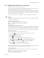
1.6
Label Positions
Stick the accessory labels in the positions shown below. Be careful not to cover the light-loader
interface or any display with the labels.
Tag number label
TIC0001A
PV
ALM
LP2
SV
MV
200
°C
Numeric label
Unit label
SET/ENT
Light-loader interface
0
O/C mark labels (Attach when the
valve’s open and close direction differs.)
IM 5D1A01-01E
C
DISP
O
1-7
Blank Page
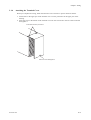
Chapter 2 Installing US1000 Controller
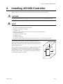
2.
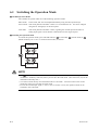
Installing US1000 Controller
Before using the controller, install it according to the instructions given in this chapter.
CAUTION
To prevent electrical shock, only apply power to the controller when it is mounted on the panel.
NOTE
To install the controller, select a location where:
·
·
·
·
·
·
·
·
·
no-one may accidentally touch the terminals
mechanical vibrations are minimal
no corrosive gas
temperature can be maintained at about 23°C and with minimal fluctuation
no direct heat radiation
no magnetic disturbances result
no splashing water
no flammable materials
the terminal board (reference junction compensation element, etc.) is protected from wind
The housing of the controller is made of modified polyphenylenether resin and polycarbonato. Be sure to install the controller away
from highly flammable items. Never place the controller directly on
highly flammable items.
If the controller has to be installed close to highly flammable items
or equipment, be sure to surround the controller with shielding
panels, placed at least 150 mm away from every side. These panels
should be made of either 1.43-mm thick metal-plated iron plates or
1.6-mm thick uncoated iron plates.
150mm
150mm
150mm
150mm
IM 5D1A01-01E
2-1
2.1
External Dimensions and Panel Dimensions
The external dimensions and panel cutout dimensions are as shown below.
Unit: mm
(approx inch)
72(2.83)
12(0.47)
149(5.87)
30(1.18)
Mounting bracket
Leave 5(0.20) mm or
more space above.
Panel thickness:1(0.04) to
10(0.39)mm
Mounting bracket
Leave 5(0.20) mm or
more space below.
135.5(5.33)
144(5.67)
136.4(5.37)
156(6.14)
62(2.44)
Weight : 0.8kg
Terminal Cover
External Dimensions
(General mounting)
(Side-by-side close mounting)
+0.7
68(2.68) 0
+2
137(5.39) 0
220(8.66) or more
137(5.39) 0
220(8.66) or more
+2
L
93(3.66) or more
L : refer to the Table 1
Panel cutout width for side-by-side
close mounting
[Table 1]
Number of units
L (mm)
L (inch)
2
140
5.51
3
212
8.35
4
284
11.18
5
356
14.02
6
428
16.85
7
500
19.69
8
572
22.52
9
644
25.35
10
716
28.19
11
788
31.02
12
860
33.86
13
932
36.69
14
1004
39.53
Panel Cutout Dimensions
2-2
IM 5D1A01-01E
Chapter 2 Installing US1000 Controller
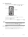
2.2
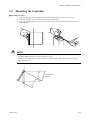
Mounting the Controller
■ Mounting Procedure
1. Cut the mounting panel as specified by the panel cutout dimensions on the previous page.
2. Insert the controller into the opening on the rear terminal board.
3. Attach the mounting brackets to the top and bottom of the controller, and fix the controller to the
mounting panel.
2.
3.
NOTE
· Do not over-tighten the screws; doing so may damage the controller housing and brackets. (Recommended tightening torque: 0.2 N•m (2 kgf•cm) or less)
· Mount the controller within 30 degrees from horizontal so that it faces upward. Do not mount it
facing downward.
Keep this angle
within 30°
IM 5D1A01-01E
2-3
Blank Page
Chapter 3 Wiring
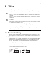
3.
Wiring
This chapter describes the wiring procedure and terminal assignment of the US1000 controller. The
optimum sets of signals are automatically assigned to the terminals according to the model and suffix
code of your controller, the controller mode (US mode), and the type of control computation output.
See Also
• Section 4.3, “Selecting the Controller Mode (US Mode),” for information on the controller modes
(US modes).
• Section 4.5, “Selecting the Control Computation and Output Types,” for information on the control
computations.
CAUTION
• Before you start wiring, turn off the power supply source and use a tester to check that the controller and cables are not receiving any power.
• Never touch a terminal when power is being supplied; you will get an electrical shock if you do.
• Be careful to connect the correct polarities. Connecting the wrong polarity may result in a serious
accident.
• If the controller and any external equipment connected to it are to be used in a hazardous area (as
non-incendive equipment), the external equipment and the wiring conditions must satisfy the
requirements specified in Appendix 6, "Conditions of Use in Hazardous Areas." If these conditions
are not satisfied, the controller itself may be the source of a fire.
3.1
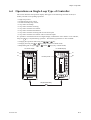
Procedure for Wiring
This section describes the cables used for wiring, the terminal assignment, and the wiring for power
supply. Once wiring is complete, a terminal cover should be attached as outlined in subsection 3.1.6.
3.1.1
Cables and Terminals
For the thermocouple input, use shielded compensating lead wires. The resistance temperature detector
(RTD) input requires shielded cables with low resistance and no resistance differential between the
three wires. The specifications for the cables and terminals used in the wiring are as follows.
600 V vinyl insulation electric wire, JIS C 3307, 0.9 to 2.0 mm2
Shielded compensating lead wire, JIS C 1610
Shielded 3-core wire, UL2482 (product of Hitachi Cable)
Crimp-on terminals with insulation sleeves and of a size suitable for
M3.5 screws (see the figure below).
• Terminal tightening torque: 0.8 N•m (8 kgf•cm) or less
•
•
•
•
Power supply wiring:
Thermocouple wiring:
RTD input wiring:
Terminal:
IM 5D1A01-01E
3.7mm
Max.7mm
Max.7mm
3.7 mm
3-1
3.1.2
Direction of wiring
After connecting cables to the rear terminals, adjust the wiring so that the cables run in the direction
shown below.
3.1.3
1
16
31
46
2
17
32
47
3
18
33
48
4
19
34
49
5
20
35
50
6
21
36
51
7
22
37
52
8
23
38
9
24
39
10
25
40
55
11
56
12
57
13
58
14
59
15
60
Preventing Noise
NOTE
• To prevent electromagnetic wave radiation, use shielded wires for the wiring for the thermocouple
input, RTD input, DC input, current output or voltage pulse output. The shiled must be grounded.
• Bundle the connected cables together tightly.
Consider the following noise-prevention points when performing wiring.
• Keep the input circuit wires as far away as possible from the power lines of other equipment.
• The use of shielded wires is effective against noises from electrostatic induction. Connect shielding
to the grounding terminal if necessary. Be sure to ground each wire independently.
• Twining input wires at short regular intervals can be quite effective at eliminating the noise from
electromagnetic induction.
• Keep the power supply wiring more than 10 cm away from the signal wiring.
3-2
IM 5D1A01-01E
Chapter 3 Wiring
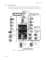
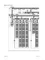
3.1.4
Terminal Designation
The terminals at the rear of the US1000 controller are arranged as shown below. Perform wiring
according to this figure. For information on the wiring for the power supply and the transmitter’s loop
power supply, read subsection 3.1.5. Refer to section 3.2 to find the signal assigned to each terminal.
OUT1A, 3A
MV output/ Retransmission output
Available for models with
option code /A10 only
16
+
OUT1A: MV output 1
17
+
OUT3A: Retransmission output
18
–
COM
Unavailable for US1000-00
LPS1
Loop power supply for
transmitter 1
AIN1
Analog input 1
• RTD input
1
19
+
20
–
AIN2
Analog input 2
• RTD input
RS-485
RS-485 communication
A
2
b
21
SDB(+)
3
B
22
SDA(-)
• Thermocouple input
1
2
+
3
–
23
RDB(+)
24
RDA(-)
25
SG
3
–
AIN3
Analog input 3
47
33
48
MV output 2
49
+
50
–
20
35
50
9
DO1: Contact output 1
10
DO2: Contact output 2
11
DO3: Contact output 3
12
6
21
36
51
7
22
37
52
8
23
38
9
24
39
10
DO1-3
COM
SUPPLY
40
25
OUT2A
Unavailable for
US1000-21
LPS2
Loop power supply for transmitter 2
51
+
52
–
For US1000-21:
FBIN
OUT1R
55
Control relay output 1
Feedback input
55
NC
55
11
56
56
NO
56
IN
12
57
57
COM
57
0% side
13
58
14
59
15
60
Power supply
13
–
32
5
Relay contact output 1-3
+
48
18
–
COM
47
17
5
8
–
3
49
DI2: Contact input 2
+
48
2
34
7
47
46
19
DI1: Contact input 1
46
31
4
6
B
16
+
DI1,2
48
• Thermocouple input
1
4
Contact input 1, 2
b
46
1
+
A
47
• Voltage input (mV, V)
• Voltage input (mV, V)
2
46
100% side
OUTR
OUT2R
Control relay output 2
Control relay output
58
NC
58
H (Direct)
59
NO
59
L (Reverse)
60
COM
60
COM
L
14
N
15
GND
DI3-7
DO4-7
Contact input 3-7
Transistor open-collector output 4-7
31
DI3: Contact input 3
36
DO4: Contact output 4
32
DI4: Contact input 4
37
DO5: Contact output 5
33
DI5: Contact input 5
38
DO6: Contact output 6
34
DI6: Contact input 6
39
DO7: Contact output 7
35
DI7: Contact input 7
40
COM
8
COM
Unavailable for US1000-00
Figure
IM 5D1A01-01E
Terminal Assignment
3-3
3.1.5
Wiring for Power Supply and Transmitter’s Loop Power Supply
Perform wiring for the power supply and the transmitter’s loop power supply as instructed below.
■ Wiring for Power Supply
• Use a single-phase power source.
• Use wires or cables with a minimum performance equivalent to that of 600 V vinyl insulation
electric wires (JIS C 3307).
• If the source has a lot of noise, use an insulation transformer and line filter as shown in the figure
below.
The recommended line filter is TDK’s ZAC2205-00U.
• When this noise-prevention measure is taken, keep the primary and secondary power cables well
apart.
• To ensure safety, install a circuit breaker switch or an equivalent safety device and be sure that
usage instructions for the device are clearly displayed.
Primary side
Secondary side
Line filter
Insulation transformer
Circuit
breaker
Controller
power
13
L
14
N
15
G
G
Class 3 grounding
■ Wiring for Loop Power Supply of Transmitter
Approximately 25.5 V DC power can be supplied to a two-wire sensor requiring a power supply.
Yokogawa’s Brain transmitter with communication function and the dedicated Brain terminal can be
used.
(Note)
2
1-5 V
3
Shielding
+
19
or
51
20
or
52
Sensor
100 Ω
Class 3 grounding
3-4
RET1
RET2
Note
Terminal numbers are 2 and 3 for AIN1 terminal,
47 and 48 for AIN2 terminal
and 4 and 5 for AIN3 terminal.
IM 5D1A01-01E
Chapter 3 Wiring
3.1.6
Attaching the Terminal Cover
When you complete the wiring, attach the terminal cover as follows to prevent electrical shocks.
1. Fit the holes in the upper part of the terminal cover over the protrusions in the upper part of the
housing.
2. Insert the screw at the bottom of the terminal cover into the screw hole in the rear of the controller
and tighten it.
Fit the holes and the protrusions
Insert the screw and tighten it
IM 5D1A01-01E
3-5
3.2
Signals Assigned to Terminals
The US1000 controller has different signals assigned to terminals depending on the controller’s model
and suffix code, the controller mode (US mode), and the type of the control computation. Refer to the
relevant subsection according to your controller’s model and suffix code.
Model US1000-00:
Subsection 3.2.1
Model US1000-11:
Subsection 3.2.2
Model US1000-21:
Subsection 3.2.3
In each subsection, tables are given for each controller mode (US mode) and control computation type.
Refer to the table that applies to your controller’s settings.
See Also
• Section 4.3, “Selecting Controller Mode (US Mode),” for information on the controller modes (US
modes).
• Section 4.5, “Selecting Control Computation and Output Types,” for information on the control
computations.
● Contact Input Function
The functions assigned to the contact inputs are as follow.
• RUN/STOP switchover:
•
•
•
•
The controller is in STOP status when the contact is on, and in the
RUN status when the contact is off.
CAS/AUTO/MAN mode selection:
When the contact is turned from off to on, the operation mode changes
to the corresponding mode.
Tracking switching:
Tracking signal of AIN2 or AIN3 is effective when the contact is on.
OPEN/CLOSE switchover: Cascade control is disabled (OPEN) when the contact is on; cascade
control is enabled (CLOSE) when contact is off.
‘PV-hold and MAN mode’ or ‘AUTO mode’:
The controller holds PV in MAN mode when the contact is on, and is
in the AUTO mode when contact is off.
● Alarm Output 1 to 4
The initial alarm types of the alarm output 1 to 4 are:
Alarm output 1:
PV high limit
Alarm output 2:
PV low limit
Alarm output 3:
PV high limit (secondary)
Alarm output 4:
PV low limit (secondary)
To change the alarm type assignments, refer to section 4.7, “Defining Alarm Outputs.”
3-6
IM 5D1A01-01E
Chapter 3 Wiring
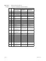
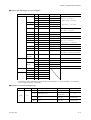
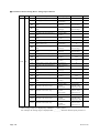
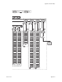
3.2.1
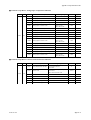
Terminal Assignment for US1000-00 (Basic Type)
■ US1000-00:
Single-loop control (US mode 1)
US1000-00:
Cascade primary-loop control (US mode 2)
US1000-00:
Cascade secondary-loop control (US mode 3)
US1000-00:
Cascade control (US mode 4)
Terminal Terminal
Code
No.
AIN1
Controller mode (US mode)
US Mode 1
US Mode 2
US Mode 3
US Mode 4
1-3
PV input
PV input
PV input
Primary-side PV input
AIN3
4, 5
Cascade input or
feedforward input
Tracking input
Cascade input
Secondary-side PV input
DI1
6, 8
RUN/STOP switchover
RUN/STOP switchover
RUN/STOP switchover
RUN/STOP switchover
DI2
7, 8
MAN mode selection
Tracking switching
CAS → AUTO mode
when the contact is off
OPEN/CLOSE
switchover
LPS1
19, 20
Loop power supply for
transmitter 1
Loop power supply for
transmitter 1
Loop power supply for
transmitter 1
Loop power supply for
transmitter 1
OUT1A
16, 18
Voltage pulse or
current output
Current output
Voltage pulse or
current output
Voltage pulse or
current output
DO1
9, 12
Alarm output 1
Alarm output 1
Alarm output 1
Alarm output 1
DO2
10, 12
Alarm output 2
Alarm output 2
Alarm output 2
Alarm output 2
DO3
11, 12
Alarm output 3
Contact off during error
Contact off when CAS mode Alarm output 3
The output from the OUT1A terminal will be voltage pulse output when the control computation is
"time proportional PID," and current output when it is "continuous PID."
■ US1000-00:
Loop control for backup (US mode 5)
US1000-00:
Loop control with PV switching (US mode 6)
US1000-00:
Loop control with PV auto-selector (US mode 7)
US1000-00:
Loop control with PV-hold function (US mode 8)
Terminal Terminal
No.
Code
Controller mode (US mode)
US Mode 5
US Mode 6
US Mode 7
US Mode 8
AIN1
1-3
PV input
PV input 1
PV input 1
PV input
AIN3
4, 5
Tracking input
PV input 2
PV input 2
Cascade input, feedforward
input, or tracking input
DI1
6, 8
RUN/STOP switchover
RUN/STOP switchover
RUN/STOP switchover
RUN/STOP switchover
Tracking switching
PV switching
MAN mode selection
'PV-hold and MAN
mode' or 'AUTO mode'
19, 20
Loop power supply for
transmitter 1
Loop power supply for
transmitter 1
Loop power supply for
transmitter 1
Loop power supply for
transmitter 1
OUT1A
16, 18
Voltage pulse or current
output
Voltage pulse or current
output
Voltage pulse or current
output
Voltage pulse or current
output
DO1
9, 12
Alarm output 1
Alarm output 1
Alarm output 1
Alarm output 1
DO2
10, 12
Alarm output 2
Alarm output 2
Alarm output 2
Alarm output 2
DO3
11, 12
Contact off during error
Alarm output 3
Alarm output 3
Alarm output 3
DI2
7, 8
LPS1
The output from the OUT1A terminal will be voltage pulse output when the control computation is
“time proportional PID,” and current output when it is “continuous PID.”
IM 5D1A01-01E
3-7
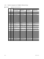
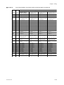
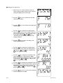
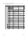
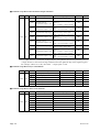
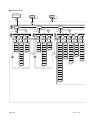
3.2.2
Terminal Assignment for US1000-11 (Enhanced Type)
■ US1000-11:
Single-loop control (US mode 1)
Control Computation (MVS1 Set Value)
Terminal Terminal Time proportional PID (0, 1)
Continuous PID (2)
Code
No.
ON/OFF computation (3)
3-8
Heating/cooling
computation (4 - 6)
Heating/cooling
computation (7 - 9)
Heating/cooling
computation (10 - 12)
AIN1
1-3
PV input
PV input
PV input
PV input
AIN2
46 - 48
No function
No function
No function
No function
AIN3
4, 5
Cascade input or
feedforward input
Cascade input or
feedforward input
Cascade input or
feedforward input
Cascade input or
feedforward input
DI1
6, 8
RUN/STOP switchover
RUN/STOP switchover
RUN/STOP switchover
RUN/STOP switchover
DI2
7, 8
MAN mode selection
MAN mode selection
MAN mode selection
MAN mode selection
DI3
31, 8
AUTO mode selection
AUTO mode selection
AUTO mode selection
AUTO mode selection
DI4
32, 8
Bit-0 of SV No. setting
Bit-0 of SV No. setting
Bit-0 of SV No. setting
Bit-0 of SV No. setting
DI5
33, 8
Bit-1 of SV No. setting
Bit-1 of SV No. setting
Bit-1 of SV No. setting
Bit-1 of SV No. setting
DI6
34, 8
Bit-2 of SV No. setting
Bit-2 of SV No. setting
Bit-2 of SV No. setting
Bit-2 of SV No. setting
DI7
35, 8
Bit-3 of SV No. setting
Bit-3 of SV No. setting
Bit-3 of SV No. setting
Bit-3 of SV No. setting
LPS1
19, 20
Loop power supply for
transmitter 1
Loop power supply for
transmitter 1
Loop power supply for
transmitter 1
Loop power supply for
transmitter 1
LPS2
51, 52
Loop power supply for
transmitter 2
Loop power supply for
transmitter 2
Loop power supply for
transmitter 2
Loop power supply for
transmitter 2
OUT1A 16, 18
Retransmission output (0, 3) Retransmission output (4) Retransmission output (7) Retransmission output (10)
Voltage pulse output (1) Heating pulse output (5) Heating pulse output (8) Heating pulse output (11)
Heating current output (6) Heating current output (9) Heating current output (12)
Current output (2)
OUT2A 49, 50
Retransmission current
output 2
Retransmission current
output 2
Cooling pulse output
Cooling current output
OUT3A 17, 18
Retransmission voltage
output 3
Retransmission voltage
output 3
Retransmission voltage
output 3
Retransmission voltage
output 3
DO1
9, 12
Alarm output 1
Alarm output 1
Alarm output 1
Alarm output 1
DO2
10, 12
Alarm output 2
Alarm output 2
Alarm output 2
Alarm output 2
DO3
11, 12
Alarm output 3
Alarm output 3
Alarm output 3
Alarm output 3
DO4
36, 40
Alarm output 4
Alarm output 4
Alarm output 4
Alarm output 4
DO5
37, 40
No function
No function
No function
No function
DO6
38, 40
No function
No function
No function
No function
DO7
39, 40
FAIL output
FAIL output
FAIL output
FAIL output
OUT1R 55 - 57
Control relay output (0, 3) Heating control relay output (4) Heating control relay output (7) Heating control relay output (10)
Alarm output 4 (1, 2)
Alarm output 4 (5, 6)
Alarm output 4 (8, 9)
Alarm output 4 (11, 12)
OUT2R 58 - 60
Alarm output 3
Cooling control relay output Alarm output 3
Alarm output 3
IM 5D1A01-01E
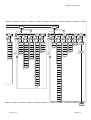
Chapter 3 Wiring
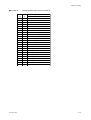
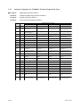
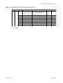
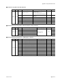
■ US1000-11:
Cascade primary-loop control (US mode 2)
Terminal Terminal
Code
No.
IM 5D1A01-01E
Control Computation (MVS1 Set Value)
Continuous PID (2)
AIN1
1-3
PV input
AIN2
46 - 48
Cascade input or feedforward input
AIN3
4, 5
Tracking input
DI1
6, 8
RUN/STOP switchover
DI2
7, 8
Tracking switching
DI3
31, 8
MAN mode selection
DI4
32, 8
Bit-0 of SV No. setting
DI5
33, 8
Bit-1 of SV No. setting
DI6
34, 8
Bit-2 of SV No. setting
DI7
35, 8
Bit-3 of SV No. setting
LPS1
19, 20
Loop power supply for transmitter 1
LPS2
51, 52
Loop power supply for transmitter 2
OUT1A 16, 18
Current output
OUT2A 49, 50
Retransmission current output 2
OUT3A 17, 18
Retransmission voltage output 3
DO1
9, 12
Alarm output 1
DO2
10, 12
Alarm output 2
DO3
11, 12
Contact off during error
DO4
36, 40
Alarm output 4
DO5
37, 40
Alarm output 3
DO6
38, 40
No function
DO7
39, 40
FAIL output
OUT1R 55 - 57
Alarm output 4
OUT2R 58 - 60
Alarm output 3
3-9
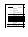
■ US1000-11:
Cascade secondary-loop control (US mode 3)
Control Computation (MVS1 Set Value)
Terminal Terminal Time proportional PID (0, 1)
Continuous PID (2)
Code
No.
ON/OFF computation (3)
3-10
Heating/cooling
computation (4 - 6)
Heating/cooling
computation (7 - 9)
Heating/cooling
computation (10 - 12)
AIN1
1-3
PV input
PV input
PV input
PV input
AIN2
46 - 48
Feedforward input
Feedforward input
Feedforward input
Feedforward input
AIN3
4, 5
Cascade input
Cascade input
Cascade input
Cascade input
DI1
6, 8
RUN/STOP switchover
RUN/STOP switchover
RUN/STOP switchover
RUN/STOP switchover
DI2
7, 8
CAS → AUTO mode
when the contact is off
CAS → AUTO mode
when the contact is off
CAS → AUTO mode
when the contact is off
CAS → AUTO mode
when the contact is off
DI3
31, 8
MAN mode selection
MAN mode selection
MAN mode selection
MAN mode selection
DI4
32, 8
AUTO mode selection
AUTO mode selection
AUTO mode selection
AUTO mode selection
DI5
33, 8
CAS mode selection
CAS mode selection
CAS mode selection
CAS mode selection
DI6
34, 8
Message input
Message input
Message input
Message input
DI7
35, 8
No function
No function
No function
No function
LPS1
19, 20
Loop power supply for
transmitter 1
Loop power supply for
transmitter 1
Loop power supply for
transmitter 1
Loop power supply for
transmitter 1
LPS2
51, 52
Loop power supply for
transmitter 2
Loop power supply for
transmitter 2
Loop power supply for
transmitter 2
Loop power supply for
transmitter 2
OUT1A 16, 18
Retransmission output (0, 3) Retransmission output (4) Retransmission output (7) Retransmission output (10)
Voltage pulse output (1) Heating pulse output (5) Heating pulse output (8) Heating pulse output (11)
Heating current output (6) Heating current output (9) Heating current output (12)
Current output (2)
OUT2A 49, 50
Retransmission current
output 2
Retransmission current
output 2
Cooling pulse output
Cooling current output
OUT3A 17, 18
Retransmission voltage
output 3
Retransmission voltage
output 3
Retransmission voltage
output 3
Retransmission voltage
output 3
DO1
9, 12
Alarm output 1
Alarm output 1
Alarm output 1
Alarm output 1
DO2
10, 12
Alarm output 2
Alarm output 2
Alarm output 2
Alarm output 2
DO3
11, 12
CAS output
CAS output
CAS output
CAS output
DO4
36, 40
Alarm output 4
Alarm output 4
Alarm output 4
Alarm output 4
DO5
37, 40
Alarm output 3
Alarm output 3
Alarm output 3
Alarm output 3
DO6
38, 40
No function
No function
No function
No function
DO7
39, 40
FAIL output
FAIL output
FAIL output
FAIL output
OUT1R 55 - 57
Control relay output (0, 3) Heating control relay output (4) Heating control relay output (7) Heating control relay output (10)
Alarm output 4 (1, 2)
Alarm output 4 (5, 6)
Alarm output 4 (8, 9)
Alarm output 4 (11, 12)
OUT2R 58 - 60
Alarm output 3
Cooling control relay output Alarm output 3
Alarm output 3
IM 5D1A01-01E
Chapter 3 Wiring
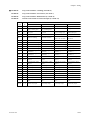
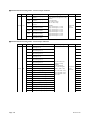
■ US1000-11:
Cascade control (US mode 4)
Control Computation (MVS2 Set value)
Terminal Terminal Time proportional PID (0, 1)
Continuous PID (2)
Code
No.
ON/OFF computation (3)
Heating/cooling
computation (7 - 9)
Heating/cooling
computation (10 - 12)
1-3
Primary-side PV input
Primary-side PV input
Primary-side PV input
Primary-side PV input
AIN2
46 - 48
Cascade input or
feedforward input
Cascade input or
feedforward input
Cascade input or
feedforward input
Cascade input or
feedforward input
AIN3
4, 5
Secondary-side PV input Secondary-side PV input Secondary-side PV input Secondary-side PV input
DI1
6, 8
RUN/STOP switchover
RUN/STOP switchover
RUN/STOP switchover
RUN/STOP switchover
DI2
7, 8
OPEN/CLOSE
switchover
OPEN/CLOSE
switchover
OPEN/CLOSE
switchover
OPEN/CLOSE
switchover
DI3
31, 8
MAN mode selection
MAN mode selection
MAN mode selection
MAN mode selection
DI4
32, 8
AUTO mode selection
AUTO mode selection
AUTO mode selection
AUTO mode selection
DI5
33, 8
CAS mode selection
CAS mode selection
CAS mode selection
CAS mode selection
DI6
34, 8
Message input
Message input
Message input
Message input
DI7
35, 8
No function
No function
No function
No function
LPS1
19, 20
Loop power supply for
transmitter 1
Loop power supply for
transmitter 1
Loop power supply for
transmitter 1
Loop power supply for
transmitter 1
LPS2
51, 52
Loop power supply for
transmitter 2
Loop power supply for
transmitter 2
Loop power supply for
transmitter 2
Loop power supply for
transmitter 2
AIN1
IM 5D1A01-01E
Heating/cooling
computation (4 - 6)
OUT1A 16, 18
Retransmission output (0, 3) Retransmission output (4) Retransmission output (7) Retransmission output (10)
Voltage pulse output (1) Heating pulse output (5) Heating pulse output (8) Heating pulse output (11)
Current output (2)
Heating current output (6) Heating current output (9) Heating current output (12)
OUT2A 49, 50
Retransmission current
output 2
Retransmission current
output 2
Cooling pulse output
Cooling current output
OUT3A 17, 18
Retransmission voltage
output 3
Retransmission voltage
output 3
Retransmission voltage
output 3
Retransmission voltage
output 3
DO1
9, 12
Alarm output 1
Alarm output 1
Alarm output 1
Alarm output 1
DO2
10, 12
Alarm output 2
Alarm output 2
Alarm output 2
Alarm output 2
DO3
11, 12
Alarm output 3
Alarm output 3
Alarm output 3
Alarm output 3
DO4
36, 40
Alarm output 4
Alarm output 4
Alarm output 4
Alarm output 4
DO5
37, 40
No function
No function
No function
No function
DO6
38, 40
No function
No function
No function
No function
DO7
39, 40
FAIL output
FAIL output
FAIL output
FAIL output
OUT1R 55 - 57
Control relay output (0, 3) Heating control relay output (4) Heating control relay output (7) Heating control relay output (10)
Alarm output 4 (1, 2)
Alarm output 4 (5, 6)
Alarm output 4 (8, 9)
Alarm output 4 (11, 12)
OUT2R 58 - 60
Alarm output 3
Cooling control relay output Alarm output 3
Alarm output 3
3-11
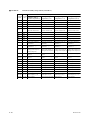
■ US1000-11:
Loop control for backup (US mode 5)
Control Computation (MVS1 Set value)
Terminal Terminal Time proportional PID (0, 1)
Continuous PID (2)
Code
No.
ON/OFF computation (3)
Heating/cooling
computation (7 - 9)
Heating/cooling
computation (10 - 12)
1-3
PV input
PV input
PV input
PV input
AIN2
46 - 48
Cascade input or
feedforward input
Cascade input or
feedforward input
Cascade input or
feedforward input
Cascade input or
feedforward input
AIN3
4, 5
Tracking input
Tracking input
Tracking input
Tracking input
DI1
6, 8
RUN/STOP switchover
RUN/STOP switchover
RUN/STOP switchover
RUN/STOP switchover
DI2
7, 8
Tracking switching
Tracking switching
Tracking switching
Tracking switching
DI3
31, 8
MAN mode selection
MAN mode selection
MAN mode selection
MAN mode selection
DI4
32, 8
Bit-0 of SV No. setting
Bit-0 of SV No. setting
Bit-0 of SV No. setting
Bit-0 of SV No. setting
DI5
33, 8
Bit-1 of SV No. setting
Bit-1 of SV No. setting
Bit-1 of SV No. setting
Bit-1 of SV No. setting
DI6
34, 8
Bit-2 of SV No. setting
Bit-2 of SV No. setting
Bit-2 of SV No. setting
Bit-2 of SV No. setting
DI7
35, 8
Bit-3 of SV No. setting
Bit-3 of SV No. setting
Bit-3 of SV No. setting
Bit-3 of SV No. setting
LPS1
19, 20
Loop power supply for
transmitter 1
Loop power supply for
transmitter 1
Loop power supply for
transmitter 1
Loop power supply for
transmitter 1
LPS2
51, 52
Loop power supply for
transmitter 2
Loop power supply for
transmitter 2
Loop power supply for
transmitter 2
Loop power supply for
transmitter 2
AIN1
3-12
Heating/cooling
computation (4 - 6)
OUT1A 16, 18
Retransmission output (0, 3) Retransmission output (4) Retransmission output (7) Retransmission output (10)
Voltage pulse output (1) Heating pulse output (5) Heating pulse output (8) Heating pulse output (11)
Heating current output (6) Heating current output (9) Heating current output (12)
Current output (2)
OUT2A 49, 50
Retransmission current
output 2
Retransmission current
output 2
Cooling pulse output
Cooling current output
OUT3A 17, 18
Retransmission voltage
output 3
Retransmission voltage
output 3
Retransmission voltage
output 3
Retransmission voltage
output 3
DO1
9, 12
Alarm output 1
Alarm output 1
Alarm output 1
Alarm output 1
DO2
10, 12
Alarm output 2
Alarm output 2
Alarm output 2
Alarm output 2
DO3
11, 12
Error output
Error output
Error output
Error output
DO4
36, 40
Alarm output 4
Alarm output 4
Alarm output 4
Alarm output 4
DO5
37, 40
Alarm output 3
Alarm output 3
Alarm output 3
Alarm output 3
DO6
38, 40
No function
No function
No function
No function
DO7
39, 40
FAIL output
FAIL output
FAIL output
FAIL output
OUT1R 55 - 57
Control relay output (0, 3) Heating control relay output (4) Heating control relay output (7) Heating control relay output (10)
Alarm output 4 (1, 2)
Alarm output 4 (5, 6)
Alarm output 4 (8, 9)
Alarm output 4 (11, 12)
OUT2R 58 - 60
Alarm output 3
Cooling control relay output Alarm output 3
Alarm output 3
IM 5D1A01-01E
Chapter 3 Wiring
■ US1000-11:
Loop control with PV switching (US mode 6)
Control Computation (MVS1 Set Value)
Terminal Terminal Time proportional PID (0, 1)
Continuous PID (2)
Code
No.
ON/OFF computation (3)
PV input 1
Heating/cooling
computation (7 - 9)
PV input 1
Heating/cooling
computation (10 - 12)
1-3
PV input 1
AIN2
46 - 48
Cascade input, feedforward Cascade input, feedforward Cascade input, feedforward Cascade input, feedforward
input, or tracking input
input, or tracking input
input, or tracking input
input, or tracking input
AIN3
4, 5
PV input 2
PV input 2
PV input 2
PV input 2
DI1
6, 8
RUN/STOP switchover
RUN/STOP switchover
RUN/STOP switchover
RUN/STOP switchover
DI2
7, 8
Dual-PV switching
Dual-PV switching
Dual-PV switching
Dual-PV switching
DI3
31, 8
MAN mode selection
MAN mode selection
MAN mode selection
MAN mode selection
DI4
32, 8
Bit-0 of SV No. setting
Bit-0 of SV No. setting
Bit-0 of SV No. setting
Bit-0 of SV No. setting
DI5
33, 8
Bit-1 of SV No. setting
Bit-1 of SV No. setting
Bit-1 of SV No. setting
Bit-1 of SV No. setting
DI6
34, 8
Bit-2 of SV No. setting
Bit-2 of SV No. setting
Bit-2 of SV No. setting
Bit-2 of SV No. setting
DI7
35, 8
Bit-3 of SV No. setting
Bit-3 of SV No. setting
Bit-3 of SV No. setting
Bit-3 of SV No. setting
LPS1
19, 20
Loop power supply for
transmitter 1
Loop power supply for
transmitter 1
Loop power supply for
transmitter 1
Loop power supply for
transmitter 1
LPS2
51, 52
Loop power supply for
transmitter 2
Loop power supply for
transmitter 2
Loop power supply for
transmitter 2
Loop power supply for
transmitter 2
AIN1
IM 5D1A01-01E
Heating/cooling
computation (4 - 6)
PV input 1
OUT1A 16, 18
Retransmission output (0, 3) Retransmission output (4) Retransmission output (7) Retransmission output (10)
Voltage pulse output (1) Heating pulse output (5) Heating pulse output (8) Heating pulse output (11)
Heating current output (6) Heating current output (9) Heating current output (12)
Current output (2)
OUT2A 49, 50
Retransmission current
output 2
Retransmission current
output 2
Cooling pulse output
Cooling current output
OUT3A 17, 18
Retransmission voltage
output 3
Retransmission voltage
output 3
Retransmission voltage
output 3
Retransmission voltage
output 3
DO1
9, 12
Alarm output 1
Alarm output 1
Alarm output 1
Alarm output 1
DO2
10, 12
Alarm output 2
Alarm output 2
Alarm output 2
Alarm output 2
DO3
11, 12
Alarm output 3
Alarm output 3
Alarm output 3
Alarm output 3
DO4
36, 40
Alarm output 4
Alarm output 4
Alarm output 4
Alarm output 4
DO5
37, 40
No function
No function
No function
No function
DO6
38, 40
No function
No function
No function
No function
DO7
39, 40
FAIL output
FAIL output
FAIL output
FAIL output
OUT1R 55 - 57
Control relay output (0, 3) Heating control relay output (4) Heating control relay output (7) Heating control relay output (10)
Alarm output 4 (1, 2)
Alarm output 4 (5, 6)
Alarm output 4 (8, 9)
Alarm output 4 (11, 12)
OUT2R 58 - 60
Alarm output 3
Cooling control relay output Alarm output 3
Alarm output 3
3-13
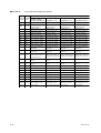
■ US1000-11:
Loop control with Dual PV auto-selector (US mode 7)
Control Computation (MVS1 Set Value)
Terminal Terminal Time proportional PID (0, 1)
Continuous PID (2)
Code
No.
ON/OFF computation (3)
PV input 1
Heating/cooling
computation (7 - 9)
PV input 1
Heating/cooling
computation (10 - 12)
1-3
PV input 1
AIN2
46 - 48
Cascade input, feedforward Cascade input, feedforward Cascade input, feedforward Cascade input, feedforward
input, or tracking input
input, or tracking input
input, or tracking input
input, or tracking input
AIN3
4, 5
PV input 2
PV input 2
PV input 2
PV input 2
DI1
6, 8
RUN/STOP switchover
RUN/STOP switchover
RUN/STOP switchover
RUN/STOP switchover
DI2
7, 8
MAN mode selection
MAN mode selection
MAN mode selection
MAN mode selection
DI3
31, 8
AUTO mode selection
AUTO mode selection
AUTO mode selection
AUTO mode selection
DI4
32, 8
Bit-0 of SV No. setting
Bit-0 of SV No. setting
Bit-0 of SV No. setting
Bit-0 of SV No. setting
DI5
33, 8
Bit-1 of SV No. setting
Bit-1 of SV No. setting
Bit-1 of SV No. setting
Bit-1 of SV No. setting
DI6
34, 8
Bit-2 of SV No. setting
Bit-2 of SV No. setting
Bit-2 of SV No. setting
Bit-2 of SV No. setting
DI7
35, 8
Bit-3 of SV No. setting
Bit-3 of SV No. setting
Bit-3 of SV No. setting
Bit-3 of SV No. setting
LPS1
19, 20
Loop power supply for
transmitter 1
Loop power supply for
transmitter 1
Loop power supply for
transmitter 1
Loop power supply for
transmitter 1
LPS2
51, 52
Loop power supply for
transmitter 2
Loop power supply for
transmitter 2
Loop power supply for
transmitter 2
Loop power supply for
transmitter 2
AIN1
3-14
Heating/cooling
computation (4 - 6)
PV input 1
OUT1A 16, 18
Retransmission output (0, 3) Retransmission output (4) Retransmission output (7) Retransmission output (10)
Voltage pulse output (1) Heating pulse output (5) Heating pulse output (8) Heating pulse output (11)
Heating current output (6) Heating current output (9) Heating current output (12)
Current output (2)
OUT2A 49, 50
Retransmission current
output 2
Retransmission current
output 2
Cooling pulse output
Cooling current output
OUT3A 17, 18
Retransmission voltage
output 3
Retransmission voltage
output 3
Retransmission voltage
output 3
Retransmission voltage
output 3
DO1
9, 12
Alarm output 1
Alarm output 1
Alarm output 1
Alarm output 1
DO2
10, 12
Alarm output 2
Alarm output 2
Alarm output 2
Alarm output 2
DO3
11, 12
Alarm output 3
Alarm output 3
Alarm output 3
Alarm output 3
DO4
36, 40
Alarm output 4
Alarm output 4
Alarm output 4
Alarm output 4
DO5
37, 40
No function
No function
No function
No function
DO6
38, 40
No function
No function
No function
No function
DO7
39, 40
FAIL output
FAIL output
FAIL output
FAIL output
OUT1R 55 - 57
Control relay output (0, 3) Heating control relay output (4) Heating control relay output (7) Heating control relay output (10)
Alarm output 4 (1, 2)
Alarm output 4 (5, 6)
Alarm output 4 (8, 9)
Alarm output 4 (11, 12)
OUT2R 58 - 60
Alarm output 3
Cooling control relay output Alarm output 3
Alarm output 3
IM 5D1A01-01E
Chapter 3 Wiring
■ US1000-11:
Loop control with PV-hold function (US mode 8)
Control Computation (MVS1 Set Value)
Terminal Terminal Time proportional PID (0, 1)
Continuous PID (2)
Code
No.
ON/OFF computation (3)
IM 5D1A01-01E
Heating/cooling
computation (4 - 6)
Heating/cooling
computation (7 - 9)
Heating/cooling
computation (10 - 12)
AIN1
1-3
PV input
PV input
PV input
PV input
AIN2
46 - 48
No function
No function
No function
No function
AIN3
4, 5
Cascade input, feedforward Cascade input, feedforward Cascade input, feedforward Cascade input, feedforward
input, or tracking input
input, or tracking input
input, or tracking input
input, or tracking input
DI1
6, 8
RUN/STOP switchover
RUN/STOP switchover
RUN/STOP switchover
RUN/STOP switchover
DI2
7, 8
'PV-hold and MAN
mode' or 'AUTO mode'
'PV-hold and MAN
mode' or 'AUTO mode'
'PV-hold and MAN
mode' or 'AUTO mode'
'PV-hold and MAN
mode' or 'AUTO mode'
DI3
31, 8
CAS mode selection
CAS mode selection
CAS mode selection
CAS mode selection
DI4
32, 8
Bit-0 of SV No. setting
Bit-0 of SV No. setting
Bit-0 of SV No. setting
Bit-0 of SV No. setting
DI5
33, 8
Bit-1 of SV No. setting
Bit-1 of SV No. setting
Bit-1 of SV No. setting
Bit-1 of SV No. setting
DI6
34, 8
Bit-2 of SV No. setting
Bit-2 of SV No. setting
Bit-2 of SV No. setting
Bit-2 of SV No. setting
DI7
35, 8
Bit-3 of SV No. setting
Bit-3 of SV No. setting
Bit-3 of SV No. setting
Bit-3 of SV No. setting
LPS1
19, 20
Loop power supply for
transmitter 1
Loop power supply for
transmitter 1
Loop power supply for
transmitter 1
Loop power supply for
transmitter 1
LPS2
51, 52
Loop power supply for
transmitter 2
Loop power supply for
transmitter 2
Loop power supply for
transmitter 2
Loop power supply for
transmitter 2
OUT1A 16, 18
Retransmission output (0, 3) Retransmission output (4) Retransmission output (7) Retransmission output (10)
Voltage pulse output (1) Heating pulse output (5) Heating pulse output (8) Heating pulse output (11)
Current output (2)
Heating current output (6) Heating current output (9) Heating current output (12)
OUT2A 49, 50
Retransmission current
output 2
Retransmission current
output 2
Cooling pulse output
Cooling current output
OUT3A 17, 18
Retransmission voltage
output 3
Retransmission voltage
output 3
Retransmission voltage
output 3
Retransmission voltage
output 3
DO1
9, 12
Alarm output 1
Alarm output 1
Alarm output 1
Alarm output 1
DO2
10, 12
Alarm output 2
Alarm output 2
Alarm output 2
Alarm output 2
DO3
11, 12
Alarm output 3
Alarm output 3
Alarm output 3
Alarm output 3
DO4
36, 40
Alarm output 4
Alarm output 4
Alarm output 4
Alarm output 4
DO5
37, 40
No function
No function
No function
No function
DO6
38, 40
No function
No function
No function
No function
DO7
39, 40
FAIL output
FAIL output
FAIL output
FAIL output
OUT1R 55 - 57
Control relay output (0, 3) Heating control relay output (4) Heating control relay output (7) Heating control relay output (10)
Alarm output 4 (1, 2)
Alarm output 4 (5, 6)
Alarm output 4 (8, 9)
Alarm output 4 (11, 12)
OUT2R 58 - 60
Alarm output 3
Cooling control relay output Alarm output 3
Alarm output 3
3-15
■ US1000-11:
US1000-11:
Dual-loop control (US mode 11)
Temperature and humidity control (US mode 12)
Control Computation (Set Value for MVS1 and MVS2)
Terminal Terminal Time proportional PID (0, 1)
Continuous PID (2)
Code
No.
ON/OFF computation (3)
3-16
Heating/cooling
computation (4, 5)
Heating/cooling
computation (6, 7)
AIN1
1-3
Loop-1 PV input
Loop-1 PV input
Loop-1 PV input
AIN2
46 - 48
Loop-2 PV input
Loop-2 PV input
Loop-2 PV input
AIN3
4, 5
Cascade input, feedforward Cascade input, feedforward Cascade input, feedforward
input, or tracking input
input, or tracking input
input, or tracking input
DI1
6, 8
RUN/STOP switchover
RUN/STOP switchover
RUN/STOP switchover
DI2
7, 8
Loop-2 MAN mode
selection
Loop-2 MAN mode
selection
Loop-2 MAN mode
selection
DI3
31, 8
Loop-1 MAN mode
selection
Loop-1 MAN mode
selection
Loop-1 MAN mode
selection
DI4
32, 8
Bit-0 of SV No. setting
Bit-0 of SV No. setting
Bit-0 of SV No. setting
DI5
33, 8
Bit-1 of SV No. setting
Bit-1 of SV No. setting
Bit-1 of SV No. setting
DI6
34, 8
Bit-2 of SV No. setting
Bit-2 of SV No. setting
Bit-2 of SV No. setting
DI7
35, 8
Bit-3 of SV No. setting
Bit-3 of SV No. setting
Bit-3 of SV No. setting
LPS1
19, 20
Loop power supply for
transmitter 1
Loop power supply for
transmitter 1
Loop power supply for
transmitter 1
LPS2
51, 52
Loop power supply for
transmitter 2
Loop power supply for
transmitter 2
Loop power supply for
transmitter 2
OUT1A 16, 18
Loop-1
Loop-1
Retransmission output 1 (0, 3) Heating pulse output (4)
Voltage pulse output (1) Cooling pulse output (5)
Current output (2)
Loop-1
Heating current output (6)
Cooling current output (7)
OUT2A 49, 50
Loop-2
Loop-2
Retransmission output 2 (0, 3) Heating pulse output (4)
Voltage pulse output (1) Cooling pulse output (5)
Current output (2)
Loop-2
Heating current output (6)
Cooling current output (7)
OUT3A 17, 18
Retransmission voltage
output 3
Retransmission voltage
output 3
Retransmission voltage
output 3
DO1
9, 12
Alarm output 1
Alarm output 1
Alarm output 1
DO2
10, 12
Alarm output 2
Alarm output 2
Alarm output 2
DO3
11, 12
Alarm output 3
Alarm output 3
Alarm output 3
DO4
36, 40
Alarm output 4
Alarm output 4
Alarm output 4
DO5
37, 40
No function
No function
No function
DO6
38, 40
No function
No function
No function
DO7
39, 40
FAIL output
FAIL output
FAIL output
OUT1R 55 - 57
Loop-1
Loop-1
Loop-1
Control relay output (0, 3) Cooling control relay output (4) Cooling control relay output (6)
Alarm output 4 (1, 2)
Heating control relay output (5) Heating control relay output (7)
OUT2R 58 - 60
Loop-2
Loop-2
Loop-2
Control relay output (0, 3) Cooling control relay output (4) Cooling control relay output (6)
Heating control relay output (5) Heating control relay output (7)
Alarm output 4 (1, 2)
IM 5D1A01-01E
Chapter 3 Wiring
■ US1000-11:
Cascade control with two universal inputs (US mode 13)
Control Computation (MVS2 Set Value)
Terminal Terminal Time proportional PID (0, 1)
Continuous PID (2)
Code
No.
ON/OFF computation (3)
IM 5D1A01-01E
Heating/cooling
computation (4 - 6)
Heating/cooling
computation (7 - 9)
Heating/cooling
computation (10 - 12)
AIN1
1-3
PV input 1
PV input 1
PV input 1
PV input 1
AIN2
46 - 48
PV input 2
PV input 2
PV input 2
PV input 2
AIN3
4, 5
Cascade input or
feedforward input
Cascade input or
feedforward input
Cascade input or
feedforward input
Cascade input or
feedforward input
DI1
6, 8
RUN/STOP switchover
RUN/STOP switchover
RUN/STOP switchover
RUN/STOP switchover
DI2
7, 8
OPEN/CLOSE
switchover
OPEN/CLOSE
switchover
OPEN/CLOSE
switchover
OPEN/CLOSE
switchover
DI3
31, 8
MAN mode selection
MAN mode selection
MAN mode selection
MAN mode selection
DI4
32, 8
AUTO mode selection
AUTO mode selection
AUTO mode selection
AUTO mode selection
DI5
33, 8
CAS mode selection
CAS mode selection
CAS mode selection
CAS mode selection
DI6
34, 8
Message input
Message input
Message input
Message input
DI7
35, 8
No function
No function
No function
No function
LPS1
19, 20
Loop power supply for
transmitter 1
Loop power supply for
transmitter 1
Loop power supply for
transmitter 1
Loop power supply for
transmitter 1
LPS2
51, 52
Loop power supply for
transmitter 2
Loop power supply for
transmitter 2
Loop power supply for
transmitter 2
Loop power supply for
transmitter 2
OUT1A 16, 18
Retransmission output (0, 3) Retransmission output (4) Retransmission output (7) Retransmission output (10)
Voltage pulse output (1) Heating pulse output (5) Heating pulse output (8) Heating pulse output (11)
Heating current output (6) Heating current output (9) Heating current output (12)
Current output (2)
OUT2A 49, 50
Retransmission current
output 2
Retransmission current
output 2
Cooling pulse output
Cooling current output
OUT3A 17, 18
Retransmission voltage
output 3
Retransmission voltage
output 3
Retransmission voltage
output 3
Retransmission voltage
output 3
DO1
9, 12
Alarm output 1
Alarm output 1
Alarm output 1
Alarm output 1
DO2
10, 12
Alarm output 2
Alarm output 2
Alarm output 2
Alarm output 2
DO3
11, 12
Alarm output 3
Alarm output 3
Alarm output 3
Alarm output 3
DO4
36, 40
Alarm output 4
Alarm output 4
Alarm output 4
Alarm output 4
DO5
37, 40
No function
No function
No function
No function
DO6
38, 40
No function
No function
No function
No function
DO7
39, 40
FAIL output
FAIL output
FAIL output
FAIL output
OUT1R 55 - 57
Control relay output (0, 3) Heating control relay output (4) Heating control relay output (7) Heating control relay output (10)
Alarm output 4 (1, 2)
Alarm output 4 (5, 6)
Alarm output 4 (8, 9)
Alarm output 4 (11, 12)
OUT2R 58 - 60
Alarm output 3
Cooling control relay output Alarm output 3
Alarm output 3
3-17
■ US1000-11:
Loop control with PV switching and two universal inputs (US mode 14)
Control Computation (MVS1 Set Value)
Terminal Terminal Time proportional PID (0, 1)
Continuous PID (2)
Code
No.
ON/OFF computation (3)
3-18
Heating/cooling
computation (4 - 6)
Heating/cooling
computation (7 - 9)
Heating/cooling
computation (10 - 12)
AIN1
1-3
PV input 1
PV input 1
PV input 1
PV input 1
AIN2
46 - 48
PV input 2
PV input 2
PV input 2
PV input 2
AIN3
4, 5
Cascade input, feedforward Cascade input, feedforward Cascade input, feedforward Cascade input, feedforward
input, or tracking input
input, or tracking input
input, or tracking input
input, or tracking input
DI1
6, 8
RUN/STOP switchover
DI2
7, 8
DI3
31, 8
DI4
DI5
RUN/STOP switchover
RUN/STOP switchover
RUN/STOP switchover
Dual-PV switching
Dual-PV switching
Dual-PV switching
Dual-PV switching
MAN mode selection
MAN mode selection
MAN mode selection
MAN mode selection
32, 8
Bit-0 of SV No. setting
Bit-0 of SV No. setting
Bit-0 of SV No. setting
Bit-0 of SV No. setting
33, 8
Bit-1 of SV No. setting
Bit-1 of SV No. setting
Bit-1 of SV No. setting
Bit-1 of SV No. setting
DI6
34, 8
Bit-2 of SV No. setting
Bit-2 of SV No. setting
Bit-2 of SV No. setting
Bit-2 of SV No. setting
DI7
35, 8
Bit-3 of SV No. setting
Bit-3 of SV No. setting
Bit-3 of SV No. setting
Bit-3 of SV No. setting
LPS1
19, 20
Loop power supply for
transmitter 1
Loop power supply for
transmitter 1
Loop power supply for
transmitter 1
Loop power supply for
transmitter 1
LPS2
51, 52
Loop power supply for
transmitter 2
Loop power supply for
transmitter 2
Loop power supply for
transmitter 2
Loop power supply for
transmitter 2
OUT1A 16, 18
Retransmission output (0, 3) Retransmission output (4) Retransmission output (7) Retransmission output (10)
Voltage pulse output (1) Heating pulse output (5) Heating pulse output (8) Heating pulse output (11)
Heating current output (6) Heating current output (9) Heating current output (12)
Current output (2)
OUT2A 49, 50
Retransmission current
output 2
Retransmission current
output 2
Cooling pulse output
Cooling current output
OUT3A 17, 18
Retransmission voltage
output 3
Retransmission voltage
output 3
Retransmission voltage
output 3
Retransmission voltage
output 3
DO1
9, 12
Alarm output 1
Alarm output 1
Alarm output 1
Alarm output 1
DO2
10, 12
Alarm output 2
Alarm output 2
Alarm output 2
Alarm output 2
DO3
11, 12
Alarm output 3
Alarm output 3
Alarm output 3
Alarm output 3
DO4
36, 40
Alarm output 4
Alarm output 4
Alarm output 4
Alarm output 4
DO5
37, 40
No function
No function
No function
No function
DO6
38, 40
No function
No function
No function
No function
DO7
39, 40
FAIL output
FAIL output
FAIL output
FAIL output
OUT1R 55 - 57
Control relay output (0, 3) Heating control relay output (4) Heating control relay output (7) Heating control relay output (10)
Alarm output 4 (1, 2)
Alarm output 4 (5, 6)
Alarm output 4 (8, 9)
Alarm output 4 (11, 12)
OUT2R 58 - 60
Alarm output 3
Cooling control relay output Alarm output 3
Alarm output 3
IM 5D1A01-01E
Chapter 3 Wiring
■ US1000-11:
Loop control with PV auto-selector and two universal inputs (US mode 15)
Control Computation (MVS1 Set Value)
Terminal Terminal Time proportional PID (0, 1)
Continuous PID (2)
Code
No.
ON/OFF computation (3)
IM 5D1A01-01E
Heating/cooling
computation (4 - 6)
Heating/cooling
computation (7 - 9)
Heating/cooling
computation (10 - 12)
AIN1
1-3
PV input 1
PV input 1
PV input 1
PV input 1
AIN2
46 - 48
PV input 2
PV input 2
PV input 2
PV input 2
AIN3
4, 5
PV input 3, cascade
PV input 3, cascade
PV input 3, cascade
PV input 3, cascade
input, feedforward input, input, feedforward input, input, feedforward input, input, feedforward input,
or tracking input
or tracking input
or tracking input
or tracking input
DI1
6, 8
RUN/STOP switchover
RUN/STOP switchover
RUN/STOP switchover
RUN/STOP switchover
DI2
7, 8
MAN mode selection
MAN mode selection
MAN mode selection
MAN mode selection
DI3
31, 8
AUTO mode selection
AUTO mode selection
AUTO mode selection
AUTO mode selection
DI4
32, 8
Bit-0 of SV No. setting
Bit-0 of SV No. setting
Bit-0 of SV No. setting
Bit-0 of SV No. setting
DI5
33, 8
Bit-1 of SV No. setting
Bit-1 of SV No. setting
Bit-1 of SV No. setting
Bit-1 of SV No. setting
DI6
34, 8
Bit-2 of SV No. setting
Bit-2 of SV No. setting
Bit-2 of SV No. setting
Bit-2 of SV No. setting
DI7
35, 8
Bit-3 of SV No. setting
Bit-3 of SV No. setting
Bit-3 of SV No. setting
Bit-3 of SV No. setting
LPS1
19, 20
Loop power supply for
transmitter 1
Loop power supply for
transmitter 1
Loop power supply for
transmitter 1
Loop power supply for
transmitter 1
LPS2
51, 52
Loop power supply for
transmitter 2
Loop power supply for
transmitter 2
Loop power supply for
transmitter 2
Loop power supply for
transmitter 2
OUT1A 16, 18
Retransmission output (0, 3) Retransmission output (4) Retransmission output (7) Retransmission output (10)
Voltage pulse output (1) Heating pulse output (5) Heating pulse output (8) Heating pulse output (11)
Heating current output (6) Heating current output (9) Heating current output (12)
Current output (2)
OUT2A 49, 50
Retransmission current
output 2
Retransmission current
output 2
Cooling pulse output
Cooling current output
OUT3A 17, 18
Retransmission voltage
output 3
Retransmission voltage
output 3
Retransmission voltage
output 3
Retransmission voltage
output 3
DO1
9, 12
Alarm output 1
Alarm output 1
Alarm output 1
Alarm output 1
DO2
10, 12
Alarm output 2
Alarm output 2
Alarm output 2
Alarm output 2
DO3
11, 12
Alarm output 3
Alarm output 3
Alarm output 3
Alarm output 3
DO4
36, 40
Alarm output 4
Alarm output 4
Alarm output 4
Alarm output 4
DO5
37, 40
No function
No function
No function
No function
DO6
38, 40
No function
No function
No function
No function
DO7
39, 40
FAIL output
FAIL output
FAIL output
FAIL output
OUT1R 55 - 57
Control relay output (0, 3) Heating control relay output (4) Heating control relay output (7) Heating control relay output (10)
Alarm output 4 (1, 2)
Alarm output 4 (5, 6)
Alarm output 4 (8, 9)
Alarm output 4 (11, 12)
OUT2R 58 - 60
Alarm output 3
Cooling control relay output Alarm output 3
Alarm output 3
3-19
3.2.3
Terminal Assignment for US1000-21 (Position Proportional Type)
■ US1000-21:
Single-loop control (US mode 1)
US1000-21:
Cascade secondary-loop control (US mode 3)
US1000-21:
Cascade control (US mode 4)
US1000-21:
Loop control for backup (US mode 5)
Terminal Terminal
Code
No.
AIN1
3-20
1-3
Controller mode (US mode)
US mode 1
PV input
US mode 3
US mode 4
US mode 5
PV input
Primary-side PV input
PV input
Cascade input or
feedforward input
AIN2
46 - 48
No function
Feedforward input
Cascade input or
feedforward input
AIN3
4, 5
Cascade input or
feedforward input
Cascade input
Secondary-side PV input Tracking switching
DI1
6, 8
RUN/STOP switchover
RUN/STOP switchover
RUN/STOP switchover
RUN/STOP switchover
OPEN/CLOSE
switchover
Tracking input
DI2
7, 8
MAN mode selection
CAS → AUTO mode
when the contact is off
DI3
31, 8
AUTO mode selection
MAN mode selection
MAN mode selection
MAN mode selection
DI4
32, 8
Bit-0 of SV No. setting
AUTO mode selection
AUTO mode selection
Bit-0 of SV No. setting
DI5
33, 8
Bit-1 of SV No. setting
CAS mode selection
CAS mode selection
Bit-1 of SV No. setting
DI6
34, 8
Bit-2 of SV No. setting
Message input
Message input
Bit-2 of SV No. setting
DI7
35, 8
Bit-3 of SV No. setting
No function
No function
Bit-3 of SV No. setting
LPS1
19, 20
Loop power supply for
transmitter 1
Loop power supply for
transmitter 1
Loop power supply for
transmitter 1
Loop power supply for
transmitter 1
LPS2
51, 52
Loop power supply for
transmitter 2
Loop power supply for
transmitter 2
Loop power supply for
transmitter 2
Loop power supply for
transmitter 2
OUT1A 16, 18
Retransmission output 1
Retransmission output 1
Retransmission output 1
Retransmission output 1
OUT2A 49, 50
Retransmission current
output 2
Retransmission current
output 2
Retransmission current
output 2
Retransmission current
output 2
OUT3A 17, 18
Retransmission voltage
output 3
Retransmission voltage
output 3
Retransmission voltage
output 3
Retransmission voltage
output 3
DO1
9, 12
Alarm output 1
Alarm output 1
Alarm output 1
Alarm output 1
DO2
10, 12
Alarm output 2
Alarm output 2
Alarm output 2
Alarm output 2
DO3
11, 12
Alarm output 3
CAS output
Alarm output 3
Error output
DO4
36, 40
Alarm output 4
Alarm output 4
Alarm output 4
Alarm output 4
DO5
37, 40
No function
Alarm output 3
No function
Alarm output 3
DO6
38, 40
No function
No function
No function
No function
DO7
39, 40
FAIL output
FAIL output
FAIL output
FAIL output
FBIN
55 - 57
Valve position feedback
input
Valve position feedback
input
Valve position feedback
input
Valve position feedback
input
OUTR
58 - 60
Position proportional
control relay output
Position proportional
control relay output
Position proportional
control relay output
Position proportional
control relay output
IM 5D1A01-01E
Chapter 3 Wiring
■ US1000-21:
Loop control with PV switching (US mode 6)
US1000-21:
Loop control with PV auto-selector (US mode 7)
US1000-21:
Loop control with PV-hold function (US mode 8)
US1000-21:
Cascade control with two universal inputs (US mode 13)
Terminal Terminal
Code
No.
IM 5D1A01-01E
Controller mode (US mode)
US mode 6
US mode 7
PV input 1
US mode 8
PV input
US mode 13
AIN1
1-3
PV input 1
PV input 1
AIN2
46 - 48
Cascade input, feedforward Cascade input, feedforward
No function
input, or tracking input
input, or tracking input
AIN3
4, 5
PV input 2
PV input 2
Cascade input, feedforward Cascade input or
input, or tracking input
feedforward input
DI1
6, 8
RUN/STOP switchover
RUN/STOP switchover
RUN/STOP switchover
RUN/STOP switchover
DI2
7, 8
Dual-PV switching
MAN mode selection
'PV-hold and MAN
mode' or 'AUTO mode'
OPEN/CLOSE
switchover
DI3
31, 8
MAN mode selection
AUTO mode selection
CAS mode selection
MAN mode selection
DI4
32, 8
Bit-0 of SV No. setting
Bit-0 of SV No. setting
Bit-0 of SV No. setting
AUTO mode selection
DI5
33, 8
Bit-1 of SV No. setting
Bit-1 of SV No. setting
Bit-1 of SV No. setting
CAS mode selection
DI6
34, 8
Bit-2 of SV No. setting
Bit-2 of SV No. setting
Bit-2 of SV No. setting
Message input
DI7
35, 8
Bit-3 of SV No. setting
Bit-3 of SV No. setting
Bit-3 of SV No. setting
No function
LPS1
19, 20
Loop power supply for
transmitter 1
Loop power supply for
transmitter 1
Loop power supply for
transmitter 1
Loop power supply for
transmitter 1
LPS2
51, 52
Loop power supply for
transmitter 2
Loop power supply for
transmitter 2
Loop power supply for
transmitter 2
Loop power supply for
transmitter 2
PV input 2
OUT1A 16, 18
Retransmission output 1
Retransmission output 1
Retransmission output 1
Retransmission output 1
OUT2A 49, 50
Retransmission current
output 2
Retransmission current
output 2
Retransmission current
output 2
Retransmission current
output 2
OUT3A 17, 18
Retransmission voltage
output 3
Retransmission voltage
output 3
Retransmission voltage
output 3
Retransmission voltage
output 3
DO1
9, 12
Alarm output 1
Alarm output 1
Alarm output 1
Alarm output 1
DO2
10, 12
Alarm output 2
Alarm output 2
Alarm output 2
Alarm output 2
DO3
11, 12
Alarm output 3
Alarm output 3
Alarm output 3
Alarm output 3
DO4
36, 40
Alarm output 4
Alarm output 4
Alarm output 4
Alarm output 4
DO5
37, 40
No function
No function
No function
No function
DO6
38, 40
No function
No function
No function
No function
DO7
39, 40
FAIL output
FAIL output
FAIL output
FAIL output
FBIN
55 - 57
Valve position feedback
input
Valve position feedback
input
Valve position feedback
input
Valve position feedback
input
OUTR
58 - 60
Position proportional
control relay output
Position proportional
control relay output
Position proportional
control relay output
Position proportional
control relay output
3-21
■ US1000-21:
US1000-21:
Loop control with PV switching and two universal inputs (US mode 14)
Loop control with PV auto-selector and two universal inputs (US mode 15)
Terminal Terminal
Code
No.
3-22
Controller mode (US mode)
US mode 14
US mode 15
AIN1
1-3
PV input 1
PV input 1
AIN2
46 - 48
PV input 2
PV input 2
AIN3
4, 5
Cascade input, feedforward PV input 3, cascade
input, or tracking input
input, feedforward input,
or tracking input
DI1
6, 8
RUN/STOP switchover
RUN/STOP switchover
DI2
7, 8
Dual-PV switching
MAN mode selection
DI3
31, 8
MAN mode selection
AUTO mode selection
DI4
32, 8
Bit-0 of SV No. setting
Bit-0 of SV No. setting
DI5
33, 8
Bit-1 of SV No. setting
Bit-1 of SV No. setting
DI6
34, 8
Bit-2 of SV No. setting
Bit-2 of SV No. setting
DI7
35, 8
Bit-3 of SV No. setting
Bit-3 of SV No. setting
LPS1
19, 20
Loop power supply for
transmitter 1
Loop power supply for
transmitter 1
LPS2
51, 52
Loop power supply for
transmitter 2
Loop power supply for
transmitter 2
OUT1A 16, 18
Retransmission output 1
Retransmission output 1
OUT2A 49, 50
Retransmission current
output 2
Retransmission current
output 2
OUT3A 17, 18
Retransmission voltage
output 3
Retransmission voltage
output 3
DO1
9, 12
Alarm output 1
Alarm output 1
DO2
10, 12
Alarm output 2
Alarm output 2
DO3
11, 12
Alarm output 3
Alarm output 3
DO4
36, 40
Alarm output 4
Alarm output 4
DO5
37, 40
No function
No function
DO6
38, 40
No function
No function
DO7
39, 40
FAIL output
FAIL output
FBIN
55 - 57
Valve position feedback
input
Valve position feedback
input
OUTR
58 - 60
Position proportional
control relay output
Position proportional
control relay output
IM 5D1A01-01E
Chapter 4 Setting the Basic Functions
4.
Setting the Basic Functions
This chapter describes the setting procedure and the meanings of the parameters used to select and
adjust the US1000 controller functions.
The parameters of the US1000 controller are largely divided into two types: “operation parameters”
and “setup parameters.”
• Operation parameters are the parameters that are changed relatively often during operation.
• Setup parameters are the parameters that determine the controller functions and are rarely changed
once they have been set.
Some parameters must be set before operation (such as the controller mode (US mode) and the input
type), while others can be set as necessary according to the user’s needs. This chapter describes the
setting procedure for parameters that must be set and those that are used often. Refer to the parameter
lists in Appendixes 3 and 4, and the parameter maps in Appendix 5 to set the other parameters.
IM 5D1A01-01E
4-1
4.1
Example of Parameter Display
To set an operation parameter or setup parameter, first call up the main menu to which the parameter
belongs. Then, from the main menu, call up the submenu which contains the parameter, and then the
target parameter from that submenu.
Appendix 5 shows the locations of all of the main menus, submenus, and parameters to help you call
up parameters.
● Examples of parameter display
When a main menu is displayed,
the top bar flashes slowly.
This decimal point flashes on
loop-2 menus.
SV
Example of a main menu display
(Loop-2 setup menu)
When a submenu is displayed, the
middle bar flashes slowly.
This decimal point flashes on
loop-2 submenus.
SV
Example of a submenu display
(Alarm setting submenu)
When a parameter is displayed,
the bottom bar flashes slowly.
This decimal point flashes on
loop-2 parameter displays.
SV
Set value
Example of a parameter display
(Alarm 1 type)
4-2
IM 5D1A01-01E
Chapter 4 Setting the Basic Functions
4.2
Procedure for Setting the Basic Functions
Always set the US1000 controller functions following the procedure below. Changing the controller
mode and input/output settings will initialize the related parameters depending on the change.
Set operation mode to MAN
Select controller mode (US mode)
See section 4.3
Select PV input type
See section 4.4
Select control computation and output types
See section 4.5
Write the data defined so far*
See section 4.6
Define alarm outputs
See section 4.7
Set target setpoint, alarm setpoints, and PID parameters
See section 4.8
Set other functions
See section 4.9
* This initializes the related parameters according to the controller mode (US mode) and PV input
type.
■ Switching the Operation Mode
key and change the operation mode to MAN. Setup
Before starting to setup the functions, press
parameters can only be set in MAN mode. Change both loop-1 and loop-2's operation mode to MAN
when the controller mode (US mode) is dual-loop control or temperature and humidity control.
PV
ALM
LP2
SV
100
Press the MAN mode key for 0.5 seconds.
SET/ENT
0
C
IM 5D1A01-01E
DISP
O
4-3
4.3
Selecting the Controller Mode (US Mode)
The controller mode (US mode) determines the basic action of the controller. The US1000 controller
has 14 selectable controller modes.
NOTE
• Since changing the controller mode resets the internal functions of the controller and initializes the
related parameters accordingly, be sure to set the controller mode before setting other parameters.
• Some controller modes cannot be selected depending on the model and suffix codes of the US1000
controller.
US1000-00: Modes that cannot be selected include dual-loop control, temperature and humidity
control, cascade control with two universal inputs, loop control with PV switching or PV autoselector and two universal inputs, and custom computation control.
US1000-21: Modes that cannot be selected include cascade primary-loop control, dual-loop control,
and temperature and humidity control.
■ Controller Mode (US Mode)
Controller mode
Setting
Description
Single-loop control
1
Basic PID control
Cascade primary-loop control
2
Operates as a primary controller in cascade control.
Cascade secondary-loop control
3
Operates as a secondary controller in cascade control.
Cascade control
4
Performs cascade control with a single controller.
Loop control for backup
5
PID control with backup function for the supervisory
system.
Loop control with PV switching
6
PID control with dual-PV switching function by contact
input or PV range.
Loop control with PV auto-selector
7
PID control with dual-PV auto-selector function by
minimum/maximum/average/difference.
Model: US1000
-00
-11
-21
NA
Loop control with PV-hold function
8
PID control with a PV- and MV-hold function.
Dual-loop control
11
Basic PID control for independent two loops.
NA
NA
Temperature and humidity control
12
Controls temperature and relative humidity
independently by PID control.
NA
NA
Cascade control with two universal inputs
13
Performs cascade control using two universal inputs.
NA
Loop control with PV switching and two
universal inputs
14
Performs loop control with PV switching using two
universal inputs.
NA
Loop control with PV auto-selector and
two universal inputs
15
Performs loop control with PV auto-selector using two
universal inputs.
NA
Custom computation control
21
Controls by user-defined control and computation
functions.
NA
NA: Not available
See Also
Block diagram for each controller mode is given in the appendix of the separate ‘US1000 Digital
Indicating Controller Functions (IM 5D1A01-02E)’ manual.
4-4
IM 5D1A01-01E
Chapter 4 Setting the Basic Functions
■ Parameter to Set Controller Mode (US Mode)
Main menu
Submenu
Parameter
Description
Setting range
Default
USMD
MD
USM
Controller mode (US mode)
See the table on the previous page.
1
■ Setting the Controller Mode (US Mode)
1. Press the
SET/ENT
key for 3 seconds from an operation
display to call up the mode menu (MODE) or
loop-1 operation menu (O.LP1).
(O.LP1 is displayed for the default setting.)
SV
MV
2. Press the
key once to call up the setup menu
(STUP). Press the
key. If a password has been
set, input the password here.
SET/ENT
SV
MV
3. The loop-1 setup menu (S.LP1) is then displayed.
Press the
key once to call up the controller
function setup menu (USMD).
4. Press the
SV
MV
SET/ENT
key to call up the controller mode
submenu (MD).
SV
MV
5. Press the
SET/ENT
key to display the controller mode
(US mode) parameter (USM).
SV
MV
6. Select the controller mode (US mode) value using
the
and
keys. (For example, select 4 for
cascade control.) A decimal point appears and
flashes. Some controller modes cannot be used
depending on the model and suffix code, in which
case their controller mode values will not be
displayed.
7. Press the
SV
MV
SET/ENT
key. The display is cleared for a
moment and the controller’s internal functions are
reset.
SV
MV
8. An operation display then appears.
SV
MV
IM 5D1A01-01E
4-5
4.4
Selecting the PV Input Type
The US1000 controller supports universal inputs and can receive the signals from a thermocouple and
RTD, and from standard signals and DC voltage signals, as PV inputs. Up to 3 inputs are available
depending on the model and suffix code, and you can set the input type and range for each input.
■ Analog Input Terminals of the US1000 Controller
The US1000 controller has a maximum of 3 analog input terminals. The AIN1, AIN2, and AIN3
terminals correspond to analog inputs 1, 2, and 3, respectively. In this section, the procedure to set
analog input 1 is described. If you are also using analog input 2 and/or 3, set them in the same
manner.
• AIN1 terminal:
• AIN2 terminal:
• AIN3 terminal:
Universal analog input terminal used for a PV input.
Universal analog input terminal. This terminal is not provided on the US100000 model (which only has AIN1 and AIN3 terminals).
Analog input terminal for voltage input and used for cascade input etc..
TIP
• Signals assigned to the analog input terminals
Setting the controller mode (US mode) automatically sets the input signals used in that controller
mode, such as the PV input, cascade input, feedforward input, tracking input, etc., to the AIN1, AIN2,
and AIN3 terminals.
See Also
Section 3.2, “Signals Assigned to Terminals,” for the signal assignment of the analog input terminals.
In this section, the procedure to set the type-J thermocouple and a measurement range of 0 to 500°C
for the AIN1 signal is described as an example.
4-6
IM 5D1A01-01E
Chapter 4 Setting the Basic Functions
■ Input Types and Ranges of Universal Inputs
Input type
Thermocouple
Setting
K
Range (°C)
Range (°F)
1
-270.0 to 1370.0⬚C
-450.0 to 2500.0°F
0⬚C and over: ⫾0.1% of F.S.
2
-270.0 to 1000.0⬚C
-450.0 to 2300.0°F
Below 0⬚C : ⫾0.2% of F.S.
K (below -200⬚C) : ⫾2% of F.S.
3
-200.0 to 500.0⬚C
-200.0 to 1000.0°F
J
4
-200.0 to 1200.0⬚C
-300.0 to 2300.0°F
T
5
-270.0 to 400.0⬚C
-450.0 to 750.0°F
6
0.0 to 400.0⬚C
-200.0 to 750.0°F
7
0.0 to 1800.0⬚C
32 to 3300°F
B
Accuracy
T (below -200⬚C) : ⫾1% of F.S.
400⬚C and over: ⫾0.1% of F.S.
Below 400⬚C : ⫾5% of F.S.
S
8
0.0 to 1700.0⬚C
32 to 3100°F
R
9
0.0 to 1700.0⬚C
32 to 3100°F
⫾0.15% of F.S.
N
10
-200.0 to 1300.0⬚C
-300.0 to 2400.0°F
⫾0.1% of F.S.
E
11
-270.0 to 1000.0⬚C
-450.0 to 1800.0°F
0⬚C and over: ⫾0.1% of F.S.
L
12
-200.0 to 900.0⬚C
-300.0 to 1600.0°F
Below 0⬚C : ⫾0.2% of F.S.
U
13
-200.0 to 400.0⬚C
-300.0 to 750.0°F
E (below -200⬚C) : ⫾1.5% of F.S.
14
0.0 to 400.0⬚C
-200.0 to 1000.0°F
⫾0.2% of F.S.
W
15
0.0 to 2300.0⬚C
32 to 4200°F
⫾0.2% of F.S.
Platinel 2
16
0.0 to 1390.0⬚C
32.0 to 2500.0°F
⫾0.1% of F.S.
PR20-40
17
0.0 to 1900.0⬚C
32 to 3400°F
800⬚C and over: ⫾0.5% of F.S.
W97Re3
18
0.0 to 2000.0⬚C
32 to 3600°F
⫾0.2% of F.S.
30
-200.0 to 500.0⬚C
-300.0 to 1000.0°F
⫾0.1% of F.S.
31
-150.00 to 150.00⬚C -200.0 to 300.0°F
⫾0.2% of F.S.
35
-200.0 to 850.0⬚C
-300.0 to 1560.0°F
⫾0.1% of F.S.
36
-200.0 to 500.0⬚C
-300.0 to 1000.0°F
37
-150.00 to 150.00⬚C -200.0 to 300.0°F
⫾0.2% of F.S.
⫾0.1% of F.S.
Below 800⬚C : Accuracy not guaranteed
W75Re25
RTD
JPt100
Pt100
(ITS90)
Standard signal
DC voltage
0.4 to 2.0 V
40
0.400 to 2.000
1 to 5 V
41
1.000 to 5.000
0 to 2 V
50
0.000 to 2.000
0 to 10 V
51
0.00 to 10.00
-10 to 20mV
55
-10.00 to 20.00
0 to 100mV
56
0.0 to 100.0
* Performance under standard operating conditions (temperature: 23 ±2°C; humidity: 55 ±10% RH;
power supply frequency: 50/60 Hz).
■ Parameters to Set the PV Input Type
Main menu
Submenu
Parameter
TYP1
USMD
IM 5D1A01-01E
Description
Setting Range
Analog input-1 type for AIN1 terminal See the table above
Default
1
UNI1
Analog input-1 unit
°C: Celsius;
°F: Fahrenheit
RH1
Maximum value of analog input-1
range
Within instrument
input range
Maximum level of
instrument range
RL1
Minimum value of analog input-1
range
Within instrument
input range
Minimum level of
instrument range
IN
°C
4-7
■ Setting the PV Input Type
1. Follow steps 1 to 3 of the controller mode (US
mode) setting procedure in the previous section to
call up the display shown on the right.
SV
MV
2. Press the
SET/ENT
key once to call up the controller
mode submenu (MD).
SV
MV
3. Press the
key once to call up the analog input
submenu (IN).
SV
MV
4.
SET/ENT
Press the
key to display the analog input-1
type parameter (TYP1). (For example, select 4 for
the type-J thermocouple.) Select the analog input1 type value using the
and
keys.
A decimal point appears and flashes when the
setting is changed.
5. Press the
SV
MV
SET/ENT
key to register the change. The
decimal point disappears.
SV
MV
6. Press the
SET/ENT
key to display the analog input-1
unit parameter (UNI1). Select the analog input-1
unit using the
and
keys, and press the
key to register the setting.
SET/ENT
SV
MV
7. Press the
SET/ENT
key to display the maximum value
of the analog input-1 range parameter (RH1).
Display the maximum value of the range you want
to set using the
and
keys, and press the
key to register the setting.
SET/ENT
8. Press the
MV
SET/ENT
key to display the minimum value of
the analog input-1 range parameter (RL1). Display
the minimum value of the range you want to set
using the
and
keys, and press the
key to register the setting.
SET/ENT
9. Press the
SV
SV
MV
key twice to return to the controller
function setup menu (USMD).
DISP
SV
MV
4-8
IM 5D1A01-01E
Chapter 4 Setting the Basic Functions
4.5
Selecting the Control Computation and Output Types
You can select the type of control computation for each control loop.
Normally, there is a single control loop. In the controller mode (US mode) for “dual-loop control” and
“temperature and humidity control”, however, the US1000 controller has two control loops and a
control computation type must be selected for each loop.
The types of control computation are listed in the table below. Each control computation has a
specific output type. The control computation for the US1000-21 model is fixed at position proportional PID and cannot be changed.
NOTE
Some control computation types cannot be selected depending on the US1000 model and suffix code.
US1000-00:
Only “time proportional PID computation with voltage pulse output” and “continuous
PID computation” can be selected.
US1000-11:
All types except for “position proportional PID computation” can be selected.
US1000-21:
Only “position proportional PID computation” can be selected. It cannot be changed.
■ Control Computation Types
Control computation type
Setting
Time proportional PID computation
with relay output
0
Outputs the PID computation results as a pulse
Control relay output
width of the time proportional on/off signal.
Time proportional PID computation
with voltage pulse output
1
Outputs the PID computation results as a pulse
Voltage pulse output
width of the time proportional on/off signal.
Continuous PID computation
2
Outputs the PID computation result as an
analog signal.
Current output
On/off computation
3
Compares the SV and PV and outputs the
on/off signal depending on whether it is a
positive or negative deviation.
Control relay output
Heating/cooling computation
(See below)
Position proportional PID
computation
4 to 12
None
Description
Output type
Outputs the PID or on/off computation result
as two signals — one for heating and the other
for cooling.
Either a control relay, voltage
pulse, or current output can be
selected for each of the heatingside and cooling-side outputs.
Controls so that the output and control valve
opening are always compatible.
Position proportional control
relay output
4: Heating control relay output • Cooling control relay output
5: Heating pulse output • Cooling control relay output
6: Heating current output • Cooling control relay output
7: Heating control relay output • Cooling pulse output
8: Heating pulse output • Cooling pulse output
9: Heating current output • Cooling pulse output
10: Heating control relay output • Cooling current output
11: Heating pulse output • Cooling current output
12: Heating current output • Cooling current output
For dual-loop control and temperature and humidity control, both loop-1 and loop-2 have the same
output combination :
4: Heating pulse output • Cooling control relay output
5: Heating control relay output • Cooling pulse output
6: Heating current output • Cooling control relay output
7: Heating control relay output • Cooling current output
IM 5D1A01-01E
4-9
■ Parameters to Set the Control Computation Type
Main menu
Submenu
USMD
Parameter
Description
MVS1
MV1 selection
MVS2
MV2 selection
OUT
Setting Range
Default
0: Control relay output,
1: Voltage pulse output,
2: Current output,
3: Control relay output for ON/OFF
computation,
4 to 12: Output for heating/cooling
computation
2
2
TIP
Either MVS1 or MVS2 will be displayed according to the controller mode (US mode). Set the
displayed parameter.
Set both for dual-loop control and temperature and humidity control.
■ Setting the Control Computation Type
1. This display represents the last step of the PV
input type setting procedure of the previous
section.
SV
MV
2. Press the
key once to call up the controller
mode submenu (MD).
SET/ENT
SV
MV
3. Press the
key twice to call up the MV output
submenu (OUT).
SV
MV
4. Press the
SET/ENT
key to display the MV1 selection
parameter (MVS1). Select the MV output type
using the
and
keys. (For example, select
1 for time proportional PID computation with
voltage pulse output.) A decimal point appears
and flashes when the setting is changed.
5. Press the
SV
MV
SET/ENT
key to register the setting. The
decimal point disappears.
SV
MV
6. Press the
DISP key twice to return to the controller
function setup menu (USMD).
SV
MV
4-10
IM 5D1A01-01E
Chapter 4 Setting the Basic Functions
4.6
Writing the Data Defined So Far (Parameter Initialization)
Once you have reached this point, you need to write the information that you have defined so far
(controller mode, PV input, and control computation) into the controller and initialize the related
parameters.
■ Parameter for Initializing Parameters
Main menu
Submenu
Parameter
USMD
INIT
INIT
Description
Parameter initialization
Setting Range
OFF, ON
Default
OFF
■ Initializing Parameters
1. This display represents the last step of the control
computation setting procedure of the previous
section.
SV
MV
2. Press the
SET/ENT
key once to call up the controller
mode submenu (MD).
SV
MV
3. Press the
key several times to call up the
parameter initialization submenu (INIT).
SV
MV
4. Press the
SET/ENT
key to display the parameter
initialization parameter (INIT). Select “ON” using
the
key. A decimal point appears and flashes
when the setting is changed.
SV
MV
5. Press the
SET/ENT
key to register the setting. The
decimal point disappears.
SV
MV
6. Press the
DISP key twice to return to the controller
function setup menu (USMD).
SV
MV
IM 5D1A01-01E
4-11
4.7
Defining the Alarm Outputs (as necessary)
The alarm outputs are pre-assigned to the US1000 controller’s contact output terminals. For example,
the US1000-00 (basic type) set up for single-loop control (US mode = 1) assigns alarm output 1,
alarm output 2 and alarm output 3 to DO1 (terminal nos. 9 and 12), DO2 (terminal nos. 10 and 12)
and DO3 (terminal nos. 11 and 12), respectively. Refer to section 3.2 for the assignments of the other
controller modes.
Any one of the alarms listed in the table below can be assigned to each alarm output.
Alarm type
Setting
Alarm type
Setting
PV high limit
1
PV high limit with waiting action
11
PV low limit
2
PV low limit with waiting action
12
High limit deviation
3
High limit deviation with waiting action
13
Low limit deviation
4
Low limit deviation with waiting action
14
Deviation of high limit passive
5
Deviation of high limit passive with waiting action
15
Deviation of low limit passive
6
Deviation of low limit passive with waiting action
16
Deviation of high and low limits
7
Deviation of high and low limits with waiting action
17
Deviation within high and low limits
8
Deviation within high and low limits with waiting action
18
PV high limit passive
9
PV high limit passive with waiting action
19
PV low limit passive
10
PV low limit passive with waiting action
20
Alarm type
Setting
SV high limit
21
SV low limit
22
MV high limit
23
MV low limit
24
PV velocity alarm
25
PV velocity alarm passive
26
Self-diagnostic alarm
27
Self-diagnostic alarm passive
28
FAIL passive
29
TIP
• The passive alarm turns the contact ON when normal, and OFF when the alarm occurs.
• The waiting action suppresses the alarm during the period from when control is started until it
stabilizes.
See Also
• Section 3.2, “Signals Assigned to Terminals,” to find the terminal to which the alarm output is
assigned.
• See section 3.14, “Parameters for Alarm Output” of the separate ‘US1000 Digital Indicating
Controller Functions’ manual, for detailed information on the alarm actions.
4-12
IM 5D1A01-01E
Chapter 4 Setting the Basic Functions
■ Parameters for Defining the Alarm Outputs
Main menu
S.LP1
S.LP2
Submenu
ALM
Parameter
Description
Setting Range
Default
AL1
Alarm 1 type
OFF, 1 to 29 (see the previous page)
1
AL2
Alarm 2 type
OFF, 1 to 29 (see the previous page)
2
AL3
Alarm 3 type
OFF, 1 to 29 (see the previous page)
1
AL4
Alarm 4 type
OFF, 1 to 29 (see the previous page)
2
After setting the controller mode (US mode) for dual-loop control or temperature and humidity
control, also set the loop-2 alarm outputs. (These parameter settings are located under the “S.LP2”
setup parameter main menu.)
IM 5D1A01-01E
4-13
■ Defining Alarm Outputs
1. This display represents the last step of the
parameter initializing procedure of the previous
section.
SV
MV
2. Press the
key once to call up the loop-1 setup
menu (S.LP1).
SV
MV
3. Press the
SET/ENT
key once to call up the target
setpoint submenu (SV).
SV
MV
4. Press the
key once to call up the alarm setting
submenu (ALM).
SV
MV
5. Press the
SET/ENT
key to display the alarm-1 type
parameter (AL1). Select the alarm type you want
to set using the
and
keys. (For example,
select 9 for PV high limit passive.) A decimal point
appears and flashes when the setting is changed.
6. Press the
SV
MV
SET/ENT
key to register the setting. The
decimal point disappears.
SV
MV
7. Press the
SET/ENT
key. If AL2 and the parameters of
other alarm types are required, also set these in the
same manner (that is, select the value you want to
set using the
and
keys, and press the
key twice).
SET/ENT
8. Press the
SV
MV
key twice to return to the controller
function setup menu (USMD).
DISP
SV
MV
4-14
IM 5D1A01-01E
Chapter 4 Setting the Basic Functions
4.8
Setting the Target Setpoint, Alarm Setpoints, and PID
Parameters
The basic operation parameters should be pre-set. You can change the settings of these parameters
after the start of operation.
■ Parameters to Set Target Setpoint, Alarm Setpoints, and PID Parameters
Main menu
O.LP1
O.LP2
Submenu Parameter
1.PID
Description
Setting Range
EU (0.0 to 100.0%)
Default
1.SV
Target setpoint
1.A1
Alarm 1 setpoint
1.A2
Alarm 2 setpoint
1.A3
Alarm 3 setpoint
1.A4
Alarm 4 setpoint
1.P
Proportional band
0.1 to 999.9%, 0.0 to 999.9% for
999.9%
heating/cooling computation
1.I
Integral time
OFF, 1 to 6000 sec.
1000 sec.
1.D
Derivative time
OFF, 1 to 6000 sec.
OFF
PV alarm: EU (-100.0 to 100.0%)
Deviation alarm/PV-velocity
alarm: EUS(-100.0 to 100.0%)
SV alarm: EU (0.0 to 100.0%)
MV alarm: -5.0 to 105.0%
EU (0%)
PV high limit: EU (100.0%)
Deviation alarm: EUS (0.0%)
MV high limit: 100.0%
MV low limit: 0.0%
PV velocity: EUS (100.0%)
Other alarms: EU (0.0%)
EU is the engineering unit corresponding to the instrument range; EUS is the engineering unit corresponding to the span of the instrument range. See Appendix 2 for further explanation.
If you use loop-2, you must also set the parameters for loop-2. (Set the parameters listed under the
“O.LP2” operation parameter main menu.)
■ Setting the Target Setpoint, Alarm Setpoints, and PID Parameters
1. This display represents the last step of the alarm
output defining procedure in the previous section.
SV
MV
2. Press the
DISP
key once. When the mode menu
(MODE) is displayed, press the
key once to
call up the loop-1 operation menu (O.LP1).
SV
MV
3. Press the
SET/ENT
key once to call up the computation
parameter submenu (PAR).
SV
MV
4. Press the
key once to call up the 1.PID
submenu (1.PID).
SV
MV
IM 5D1A01-01E
4-15
5. Press the
SET/ENT
key once to display the target
setpoint parameter (1.SV). Set the target setpoint
value you want to set using the
and
keys.
The decimal point flashes.
SV
MV
6. Press the
SET/ENT
key to register the setting. The
decimal point stops flashing.
SV
MV
7. Press the
SET/ENT
key to display the alarm-1 setpoint
parameter (1.A1). This is the alarm setpoint that
corresponds to the “alarm-1 type” set in the
previous section. Set the alarm setpoint value you
want to set using the
and
keys. The
decimal point flashes.
8. Press the
SV
MV
SET/ENT
key to register the setting. The
decimal point stops flashing.
SV
MV
9. Press the
SET/ENT
key to display the alarm-2 setpoint
parameter (1.A2). Set it in the same manner as
1.A1 (that is, select the value you want to set using
the
and
keys, and press the
key
twice). If you do not need to make a setting, just
press the
key.
SET/ENT
SV
MV
SET/ENT
10. Set 1.A3 and 1.A4 in the same manner (that is,
select the value you want to set using the
and
keys, and press the
key twice). If you do
not need to make a setting, just press the
key.
SET/ENT
SET/ENT
SV
MV
11. Set the proportional band (1.P), integral time (1.I),
and derivative time (1.D) in the same manner (that
is, select the value you want to set using the
and
keys, and press the
key twice).
SET/ENT
SV
MV
12. Press the
DISP key twice to return to the loop-1
operation menu (O.LP1).
SV
MV
4-16
IM 5D1A01-01E
Chapter 4 Setting the Basic Functions
4.9
Setting Other Functions (as necessary)
Set the functions described in this section as necessary.
This section describes the parameter setting procedure using the setting of the direct/reverse action of
control as an example. Set other parameters in the same way, as necessary.
Before setting, confirm the setting range of parameters referring to the parameter lists in Appendixes 3
and 4. When you set parameters, the parameter maps in Appendix 5 are helpful because they illustrate
the display sequence and locations of the parameters. You can use the maps as an operation guide to
call up the parameters you want to set or change.
If you are also using loop-2, set loop-2 parameters in the same manner as the loop-1 parameters.
See Also
See chapter 3 of the separate ‘US1000 Digital Indicating Controller Functions’ manual, for deatailed
information on each parameter.
(1) Direct/reverse action of control
You can specify either a direct or reverse action of control.
Menu:
[Operation parameter]-[O.LP1/O.LP2]-[1.PID]
Parameter: 1.DR
● Setting Direct/Reverse Action of Control
First, determine the values of the parameters to be set by referring to the parameter list in Appendix 3.
Look at the operation parameter map in Appendix 5. Find the main menu “O.LP1” and check that the
submenu “1.PID” is located below it. Then, find the parameter “1.DR” below the submenu “1.PID.”
The parameter map shows the keys (by key symbols) used in reaching the parameter “1.DR” starting
from an operation display.
Perform the following operations looking at the parameter map.
1. First, press the
SET/ENT
2. Next, press the
3. Press the
SET/ENT
4. Press the
5. Press the
key for 3 seconds from an operation display to call up “MODE.”
key once to call up “O.LP1.”
key to call up “PAR.”
key once to call up “1.PID.”
SET/ENT
key several times until the “1.DR” parameter is displayed.
6. Change the setting using the
7. Press the
SET/ENT
or
key. A decimal point will appear and flash.
key to register the new setting. Then, the decimal point disappears.
8. When all the settings are finished, press the
DISP
key to return to the submenu.
9. Pressing the
DISP
key at a submenu returns to the main menu.
Pressing the
DISP
key at a main menu returns to an operation display.
Set the following parameters referring to the parameter lists in Appendixes 3 and 4 and the parameter
map in Appendix 5, as done for the direct/reverse action parameter setting.
(2) PV filter and PV bias
First order lag filtering function, and bias adding function used for correction in reference junction
compensation
Menu:
[Operation parameter]-[O.LP1/O.LP2]-[PAR]
Parameter: BS (PV bias), FL (PV filter)
IM 5D1A01-01E
4-17
(3) 10-segment linearizer
Can be selected as one of the following two functions.
Biasing:
Provides biasing on any arbitrary 11 points of input.
Approximation:
Output values can be arbitrarily set against the arbitrary 11 points of input.
Menu:
Parameter:
[Operation parameter]-[PYS1]
1.X1 to 1.X11, 1.Y1 to 1.Y11, 1.PMD
(4) Burnout action
Sets the action upon detection of a burnout (wire breakage) for the thermocouple, RTD, and the
standard signal inputs.
Menu:
[Setup parameter]-[CMLP]-[AIN]
Parameter: A.BO1, A.BO2, A.BO3
(5) Cascade input source
The cascade input source can be selected as either an analog input terminal or as RS-485 communication. (The factory-set default is analog input terminal.)
When you use the feedforward input instead of the cascade input, set the CMS parameter to “CPT”.
Menu:
[Setup parameter]-[S.LP1/S.LP2]-[SV]
Parameter: CMS
(6) Feedforward input
To use the feedforward input, set the FFS parameter to “AIN” and set the CMS (cascade input source)
parameter to “CPT”. A filter and computation for feedforward input are provided.
Menu:
Parameter:
Menu:
Parameter:
[Setup parameter]-[S.LP1]-[CTL]
FFS
[Operation parameter]-[O.LP1]-[PAR]
FGN, FBI, FBO, FFL
(7) Square-root computation
Square-root extraction with changeable low signal cut-off point.
Menu:
[Setup parameter]-[CMLP]-[AIN]
Parameter: A.SR1, A.LC1, A.SR2, A.LC2, A.SR3, A.LC3
(8) SUPER function
This function suppresses overshoots. It is more effective when used together with the auto-tuning
function.
Menu:
[Operation parameter]-[O.LP1/O.LP2]-[PAR]
Parameter: SC
(9) PV tracking
This function prevents a sudden changes in PV by temporarily making SV track PV when the controller is switched to AUTO mode.
Menu:
[Setup parameter]-[S.LP1 / S.LP2]-[SV]
Parameter: PVT
(10) SV ramp-up/ramp-down rate
This functions is used as an SV changing operation, to gradually change SV toward the new value at a
constant rate.
Menu:
Parameter:
Menu:
Parameter:
4-18
[Setup parameter]-[S.LP1/S.LP2]-[SV]
TMU (time unit for ramp-rate setting)
[Operation parameter]-[O.LP1 / O.LP2]-[PAR]
UPR, DNR (setpoint ramp-up/ramp-down)
IM 5D1A01-01E
Chapter 4 Setting the Basic Functions
(11) Cycle time of MV output (Pulse width of on/off signal)
The pulse width of an on/off signal in time proportional PID computation is proportional to the cycle
time of the MV output.
Pulse width of MV output = MV output (%) × cycle time of MV output
Menu:
[Setup parameter]-[CMLP]-[C.CTL]
Parameter: CT1, CT2
(12) Preset PID
You can set multiple sets of PID parameters. For detailed information about preset PIDs, read section
3.10 of the separate ‘US1000 Digital Indicating Controller Functions’ manual.
Menu:
[Setup parameter]-[CMLP]-[C.CTL]
Parameter: PPID (specifies either SV number selection or zone PID)
(13) Behavior upon power recovery
You can set the type of controller behavior upon power recovery.
HOT:
COLD:
Menu:
Parameter:
Continues the same operation as prior to power failure.
Starts in MAN mode. Outputs the preset MV value.
[Setup parameter]-[CMLP]-[C.CTL]
R.MD
(14) Retransmission output
The function to re-transmit PV, MV, and SV data as an analog signal.
Menu:
[Setup parameter]-[CMLP]-[RET]
Parameter: RET1, RTH1, RTL1, RET2, RTH2, RTL2, RET3, RTH3, RTL3
(15) Password setting for parameter change operation
You can set a password to prevent accidental or careless changes to setup parameter settings. The
password is verified in the transmission from the operation parameter display to the setup parameter
display.
The password setting range is from 0 (no password) to 30000.
NOTE
• Be sure to memorize the password. Once a password has been set, you cannot transmit to the setup
parameter setting display without entering the correct password. To cancel a lost password, the
controller must be sent back to a Yokogawa service center for repair at your cost.
• In the repair service, all parameters are initialized to the factory-set defaults. Thus, it is recommended to keep records of the user-set values for all of the parameters.
Menu:
[Setup parameter]-[CMLP]-[MLCK]
Parameter: PWD
(16) Prohibition of key operation and parameter setting
You can disable (i.e., lock) specific operation keys and set specific operation parameter menus so that
they will not be displayed.
Menu:
[Setup parameter]-[CMLP]-[KLCK]
Parameter: SVC (SV setting key lock at operation displays)
/
(Data setting key lock)*1
</>
(MV operation key lock)
C
(C mode key lock)
A
(A mode key lock)
M
(M mode key lock)*2
IM 5D1A01-01E
4-19
Menu:
[Setup parameter]-[CMLP]-[MLCK]
Parameter: MODE (Mode menu lock)
O.LP1 (O.LP1 menu lock)
O.LP2 (O.LP2 menu lock)
PID
(PID submenu lock)*3
USR (USR menu lock)
PYS1 (PYS1 menu lock)
PYS2 (PYS2 menu lock)
*1: Disables all parameter setting operations except those for the parameters included in the key lock
submenu KLCK and the password setting parameter.
*2: While the setup parameter menu (STUP) is displayed, the M mode key lock becomes invalid and
the operation mode can be switched to MAN.
*3: Locks all of the submenus of 1.PID through to 8.PID.
(17) Calibration of valve position (US1000-21 only)
To perform position proportional control, you must set the valve position data of 0% and 100%
openings to the controller.
You can calibrate the valve position either automatically or manually.
NOTE
Perform this calibration with the controller connected to the control valve.
Menu:
[Setup parameter]-[USMD]-[VALV]
Parameter: V.RS, V.L, V.H, V.AT
● Calibrating the valve position (manually)
1. Display the V.RS parameter listed under the menu above. If V.RS is flashing, it means that the
valve position has not been calibrated yet.
key to select “1.” (If it is already 1, set it back to 0 first and then reset it to 1.)
Press the
Press the
SET/ENT
key to reset the valve position settings.
2. Press the
SET/ENT
key to display the V.L parameter.
Press and hold down the
key. This operates to close the valve and decrease the value on the
SV digital display. When the digital value stops decreasing, the valve is fully closed.
Press the
SET/ENT
key. The 0% opening is adjusted, and the SV digital display indicates 0.
3. Press the
SET/ENT
key to display the V.H parameter.
Press and hold down the
key. This operates to open the valve and increase the value on the
SV digital display. When the digital value stops increasing, the valve is fully opened.
Press the
SET/ENT
key. The 100% opening is adjusted, and the SV digital display indicates 100.
● Calibrating valve position (automatically)
1. Call up the V.AT parameter, and press the
Press the
SET/ENT
key to select “ON.”
key. The parameter starts flashing. When it stops flashing, calibration is completed.
If “ERR” is displayed, there may be some trouble in the wiring, valve, or process. Press the
DISP
key to clear the error, and check the valve, process status, and so on.
4-20
IM 5D1A01-01E
Chapter 5 Customizing Operation Displays
5.
Customizing Operation Displays
In addition to the standard operation displays, two types of operation displays can be created according
to your needs.
● USER Display
Data that needs to be referred to during the normal operation display sequence, can be displayed on
the digital display. These displays are called “USER displays.” You can transfer from the last
operation display to the USER display using the DISP key. When more than one USER display has
been registered, the USER displays appear in sequence every time the DISP key is pressed.
● SELECT Display
You can select the operation parameters that are frequently checked or modified by simply calling
them up from an operation display. This resulting display is called a “SELECT display.” You can call
key for less than 3 seconds. If
up SELECT displays from any operation display by pressing the
you press the key for more than 3 seconds, the mode menu appears. In this case, go back to an
operation display by pressing the DISP key and try again. When more than one SELECT display has
key is pressed. To
been registered, the SELECT displays appear in sequence every time the
return to an operation display, press the DISP key.
SET/ENT
SET/ENT
DISP
Operation display 1
DISP
Operation display 2
DISP
USER display
(alarm)
DISP
USER display
(PID group No.)
DISP
USER display
(others)
DISP
SET/ENT
DISP
DISP
Press for less than 3 seconds.
SET/ENT
SELECT display 1
SELECT display 2
SET/ENT
IM 5D1A01-01E
SET/ENT
SELECT display 5
SET/ENT
5-1
5.1
Registering Auxiliary Operation Displays (USER Displays)
The types of USER displays are listed in the table below. You can select and register the USER
displays you need during operation. The registered displays are then displayed using the DISP key in
the order shown in the table. The initial values of the parameters in the table are all “OFF” (not
registered). Set the parameters you want to register to “ON.”
Menu: [Setup parameter] - [CONF] - [U.OPE]
Parameter
Meaning
PV digital display
SV digital display
U. 1AL
Loop-1 alarm
L1. ALM
Number of occurring alarm (1 - 4)
U. 2AL
Loop-2 alarm
L2. ALM
Number of occurring alarm (1 - 4)
U. SVN
SV number
SVNO
Specified SV number (1 - 8)
U. 1PI
Loop-1 PID group number
L1. PID
Current PID group number (1 - 8) for zone PID
U. 2PI
Loop-2 PID group number
L2. PID
Current PID group number (1 - 8) for zone PID
U. AI1
AIN1 measured value
AIN1
AIN1 value (engineering unit)
U. AI2
AIN2 measured value
AIN2
AIN2 value (engineering unit)
U. AI3
AIN3 measured value
AIN3
AIN3 value (engineering unit)
U. PV1
PV1
PV1
PV1 value (engineering unit)
U. PV2
PV2
PV2
PV2 value (engineering unit)
U. SMP
Sampling error counter
SMP. ER
Error counter (0 - 30000)
See Also
• See section 3.10 of the separate ‘US1000 Digital Indicating Controller Functions’ manual, for SV
number and zone PID.
• See section 3.17 of the separate ‘US1000 Digital Indicating Controller Functions’ manual, for
sampling error counter.
5-2
IM 5D1A01-01E
Chapter 5 Customizing Operation Displays
■ Examples of USER Display
● USER display of Loop-1 alarm
SV
SV
SV
MV
MV
MV
Alarms 1 to 4 are all activated
Alarm 1 and 3 are activated
No alarm in occurrence
● USER display of SV number
SV
MV
Specified SV number is 1.
● USER display of loop-1 PID group number
SV
MV
Current PID group number for zone PID is 2.
● USER display of AIN1 measured value
SV
MV
AIN1 = 1789
● USER display of PV1
SV
SV
SV
MV
MV
MV
PV1 = 12.34
PV1 overflow
PV1 underflow
● USER display of sampling error counter
SV
MV
Error count is 12345.
IM 5D1A01-01E
5-3
■ Registering USER Displays
1.
If the controller is not in MAN mode, press the
key
to change to MAN mode.
In an operation display, pressing the
key for 3
seconds will retrieve the mode menu (MODE) or
loop-1 operation mode (O.LP1).
(O.LP1 is displayed for the default setting.)
SET/ENT
2.
Press the
key once to display the setup menu
(STUP).
Then press the
key once.
If a password has been set, input the password here.
SET/ENT
3.
The loop-1 setup menu (S.LP1) appears.
Press the
key several times to display the detailed
function setup menu (CONF).
SV
MV
SV
MV
SV
MV
4.
SET/ENT
Press the
key once to display the SELECT display
registration submenu (C.SEL).
Then press the
key once to display the USER
display registration submenu (U.OPE).
SV
MV
5.
Press the
key to display the USER display of the
loop-1 alarm parameter (U.1AL).
To register the USER display for use during operation, press
the
key and select “ON,” and then press the
key.
(If you do not need the USER display, leave it “OFF” and
press SET/ENT key.)
SET/ENT
SET/ENT
6.
Press the
key to display the next USER display
registration parameter. Set the parameters for the USER
displays you want to "ON" in the same way as for U.1AL
above.
SV
MV
SET/ENT
SV
MV
7.
Press the DISP key for 3 seconds to return to the
operation display.
SV
MV
5-4
IM 5D1A01-01E
Chapter 5 Customizing Operation Displays
5.2
Displaying the Alarm Status
If the USER display functions described in the previous section are used, you can display alarm
statuses from an operation display by pressing the DISP key.
To set up the alarm status display function, perform the following.
1. Define alarm actions: Refer to section 4.7, “Defining Alarm Outputs.”
2. Set alarm setpoints: Refer to section 4.8, “Setting Target Setpoint, Alarm Setpoints, and PID
Parameters.”
3. Set the U.1AL or U.2AL (USER display) parameter to ON:
Refer to section 5.1, “Registering Auxiliary Operation Displays (USER
Displays).”
IM 5D1A01-01E
5-5
5.3
Registering Quick Parameter Call-up Functions (SELECT Displays)
You can register up to 5 SELECT displays. An operation parameter that is frequently checked or
modified during operation should be registered as a SELECT display. Registration involves setting
the D-register numbers of operation parameters. The D-register numbers are given in the table on the
next page.
■ Examples of SELECT Display
SV
SV
SV
MV
MV
MV
SELECT display for the U1
parameter
A register number with no
allocated parameter has been
set for SELECT display 2.*1
A register number of nondisplayable parameter has been
set for SELECT display 4.*2
*1: If you happen to register a D-register number that is not allocated to a parameter (i.e., a D-register
number not found in the table on the next page), the SELECT display will indicate “NoMAP” followed by as many hyphens as the number of digits in the SELECT display number (1 to 5 digits).
*2: Some parameters are not displayed depending on the controller mode (US mode) and the model
and suffix code of the controller. If you register such parameters, the SELECT display will indicate
“SKIP” followed by as many hyphens as the number of digits in the SELECT display number (1 to 5
digits).
■ Parameters to Register SELECT Displays
Main menu
CONF
5-6
Submenu
C. SEL
Parameter
Description
Range of setting
Default
C.S1 - C.S5
Registration of SELECT
display 1 to 5
OFF, 201 to 773
OFF
IM 5D1A01-01E
Chapter 5 Customizing Operation Displays
■ D-register Numbers of Operation Parameters
No.
Parameter
Mode
206
O/C
207
SVNO
Loop-1 computation parameters
241
AT. 1
242
SC. 1
243
BS. 1
244
FL. 1
245
UPR. 1
246
DNR. 1
247
CRT. 1
248
CBS. 1
249
CFL. 1
250
FGN. 1
251
FBI. 1
252
FBO. 1
253
FFL. 1
Loop-2 computation parameters
271
AT. 2
272
SC. 2
273
BS. 2
274
FL. 2
275
UPR. 2
276
DNR. 2
277
CRT. 2
278
CBS. 2
279
CFL. 2
Loop-1 1. PID
301
1. SV
302
1. A1
303
1. A2
304
1. A3
305
1. A4
306
1. P
307
1. I
308
1. D
309
1. MH
310
1. ML
311
1. MR
312
1. H
313
1. DR
314
1. Pc
315
1. Ic
316
1. Dc
317
1. Hc
318
1. DB
319
1. RP
320
1. PM
321
1. PMc
Loop-1 2. PID
326
2. SV
327
2. A1
328
2. A2
329
2. A3
330
2. A4
331
2. P
332
2. I
333
2. D
334
2. MH
335
2. ML
336
2. MR
337
2. H
338
2. DR
339
2. Pc
340
2. Ic
341
2. Dc
342
2. Hc
343
2. DB
344
2. RP
345
2. PM
346
2. PMc
IM 5D1A01-01E
No.
Parameter
Loop-1 3. PID
351
3. SV
352
3. A1
353
3. A2
354
3. A3
355
3. A4
356
3. P
357
3. I
358
3. D
359
3. MH
360
3. ML
361
3. MR
362
3. H
363
3. DR
364
3. Pc
365
3. Ic
366
3. Dc
367
3. Hc
368
3. DB
369
3. RP
370
3. PM
371
3. PMc
Loop-1 4. PID
376
4. SV
377
4. A1
378
4. A2
379
4. A3
380
4. A4
381
4. P
382
4. I
383
4. D
384
4. MH
385
4. ML
386
4. MR
387
4. H
388
4. DR
389
4. Pc
390
4. Ic
391
4. Dc
392
4. Hc
393
4. DB
394
4. RP
395
4. PM
396
4. PMc
Loop-1 5. PID
401
5. SV
402
5. A1
403
5. A2
404
5. A3
405
5. A4
406
5. P
407
5. I
408
5. D
409
5. MH
410
5. ML
411
5. MR
412
5. H
413
5. DR
414
5. Pc
415
5. Ic
416
5. Dc
417
5. Hc
418
5. DB
419
5. RP
420
5. PM
421
5. PMc
No.
Parameter
Loop-1 6. PID
426
6. SV
427
6. A1
428
6. A2
429
6. A3
430
6. A4
431
6. P
432
6. I
433
6. D
434
6. MH
435
6. ML
436
6. MR
437
6. H
438
6. DR
439
6. Pc
440
6. Ic
441
6. Dc
442
6. Hc
443
6. DB
444
6. RP
445
6. PM
446
6. PMc
Loop-1 7. PID
451
7. SV
452
7. A1
453
7. A2
454
7. A3
455
7. A4
456
7. P
457
7. I
458
7. D
459
7. MH
460
7. ML
461
7. MR
462
7. H
463
7. DR
464
7. Pc
465
7. Ic
466
7. Dc
467
7. Hc
468
7. DB
469
RHY
470
7. PM
471
7. PMc
Loop-1 8. PID
476
8. SV
477
8. A1
478
8. A2
479
8. A3
480
8. A4
481
8. P
482
8. I
483
8. D
484
8. MH
485
8. ML
486
8. MR
487
8. H
488
8. DR
489
8. Pc
490
8. Ic
491
8. Dc
492
8. Hc
493
8. DB
494
RDV
495
8. PM
496
8. PMc
No.
Parameter
Loop-2 1. PID
501
1. SV
502
1. A1
503
1. A2
504
1. A3
505
1. A4
506
1. P
507
1. I
508
1. D
509
1. MH
510
1. ML
511
1. MR
512
1. H
513
1. DR
514
1. Pc
515
1. Ic
516
1. Dc
517
1. Hc
518
1. DB
519
1. RP
520
1. PM
521
1. PMc
Loop-2 2. PID
526
2. SV
527
2. A1
528
2. A2
529
2. A3
530
2. A4
531
2. P
532
2. I
533
2. D
534
2. MH
535
2. ML
536
2. MR
537
2. H
538
2. DR
539
2. Pc
540
2. Ic
541
2. Dc
542
2. Hc
543
2. DB
544
2. RP
545
2. PM
546
2. PMc
Loop-2 3. PID
551
3. SV
552
3. A1
553
3. A2
554
3. A3
555
3. A4
556
3. P
557
3. I
558
3. D
559
3. MH
560
3. ML
561
3. MR
562
3. H
563
3. DR
564
3. Pc
565
3. Ic
566
3. Dc
567
3. Hc
568
3. DB
569
3. RP
570
3. PM
571
3. PMc
No.
Parameter
Loop-2 4. PID
576
4. SV
577
4. A1
578
4. A2
579
4. A3
580
4. A4
581
4. P
582
4. I
583
4. D
584
4. MH
585
4. ML
586
4. MR
587
4. H
588
4. DR
589
4. Pc
590
4. Ic
591
4. Dc
592
4. Hc
593
4. DB
594
4. RP
595
4. PM
596
4. PMc
Loop-2 5. PID
601
5. SV
602
5. A1
603
5. A2
604
5. A3
605
5. A4
606
5. P
607
5. I
608
5. D
609
5. MH
610
5. ML
611
5. MR
612
5. H
613
5. DR
614
5. Pc
615
5. Ic
616
5. Dc
617
5. Hc
618
5. DB
619
5. RP
620
5. PM
621
5. PMc
Loop-2 6. PID
626
6. SV
627
6. A1
628
6. A2
629
6. A3
630
6. A4
631
6. P
632
6. I
633
6. D
634
6. MH
635
6. ML
636
6. MR
637
6. H
638
6. DR
639
6. Pc
640
6. Ic
641
6. Dc
642
6. Hc
643
6. DB
644
6. RP
645
6. PM
646
6. PMc
No.
Parameter
Loop-2 7. PID
651
7. SV
652
7. A1
653
7. A2
654
7. A3
655
7. A4
656
7. P
657
7. I
658
7. D
659
7. MH
660
7. ML
661
7. MR
662
7. H
663
7. DR
664
7. Pc
665
7. Ic
666
7. Dc
667
7. Hc
668
7. DB
669
RHY
670
7. PM
671
7. PMc
Loop-2 8. PID
676
8. SV
677
8. A1
678
8. A2
679
8. A3
680
8. A4
681
8. P
682
8. I
683
8. D
684
8. MH
685
8. ML
686
8. MR
687
8. H
688
8. DR
689
8. Pc
690
8. Ic
691
8. Dc
692
8. Hc
693
8. DB
694
RDV
695
8. PM
696
8. PMc
User parameters
701
U1
702
U2
703
U3
704
U4
705
U5
706
U6
707
U7
708
U8
No.
Parameter
Ten-segment linearizer 1
726
1. X1
727
1. Y1
728
1. X2
729
1. Y2
730
1. X3
731
1. Y3
732
1. X4
733
1. Y4
734
1. X5
735
1. Y5
736
1. X6
737
1. Y6
738
1. X7
739
1. Y7
740
1. X8
741
1. Y8
742
1. X9
743
1. Y9
744
1. X10
745
1. Y10
746
1. X11
747
1. Y11
748
1. PMD
Ten-segment linearizer 2
751
2. X1
752
2. Y1
753
2. X2
754
2. Y2
755
2. X3
756
2. Y3
757
2. X4
758
2. Y4
759
2. X5
760
2. Y5
761
2. X6
762
2. Y6
763
2. X7
764
2. Y7
765
2. X8
766
2. Y8
767
2. X9
768
2. Y9
769
2. X10
770
2. Y10
771
2. X11
772
2. Y11
773
2. PMD
5-7
■ Registering SELECT Displays
1.
If the controller is not in MAN mode, press the
key
to change to MAN mode.
In an operation display, pressing the
key for 3
seconds will retrieve the mode menu (MODE) or
SET/ENT
loop-1 operation mode (O.LP1).
(O.LP1 is displayed for the default setting.)
2.
Press the
key once to display the setup menu
(STUP).
Then press the
key once.
If a password has been set, input the password here.
SV
MV
SET/ENT
3.
The loop-1 setup menu (S.LP1) then appears.
Press the
key several times to display the detailed
function setup menu (CONF).
SV
MV
SV
MV
4.
Press the
key once to display the SELECT display
registration submenu (C.SEL).
SET/ENT
SV
MV
5.
6.
Press the
key to enable registration of the SELECT
display 1 parameter (C.S1).
Find the D-register number of the operation parameter
you want to register in the table on the previous page,
and set it using the
and
keys.
Example: To register the alarm-1 setpoint (1.A1), set
"302."
SET/ENT
SV
MV
Press the
key to register the setting. The decimal
point stops flashing.
SET/ENT
SV
MV
7.
SET/ENT
Press the
key once again to enable registration of
the SELECT display 2 parameter (C.S2). Set the
parameters of other SELECT displays (C.S2 to C.S5) as
necessary, and in the same manner as done for C.S1.
SV
MV
8.
Press the DISP key for 3 seconds to return to the
operation display.
SV
MV
5-8
IM 5D1A01-01E
Chapter 6 Operation
6.
Operation
Now that you have completed the installation, wiring and functionality setup procedures described in
the previous chapters, you can actually start operating the US1000.
This chapter describes the basic operations of the US1000 and specific operations for individual
controller modes (US modes). It also explains basic tuning work and switching among the CAS,
AUTO, and MAN modes by the contact inputs.
TIP
This chapter describes the controller operation of the following three types of controllers depending on
their selected controller mode (US mode).
Controller type
Single-loop type
Preset controller mode (US mode)
Single-loop control, cascade primary-loop control, cascade secondary-loop control, loop control
for backup, loop control with PV switching, loop control with PV auto-selector, loop control
with PV-hold function, loop control with PV switching and two universal inputs, loop control
with PV auto-selector and two universal inputs
Cascade type
Cascade control, cascade control with two universal inputs
Dual-loop type
Dual-loop control, temperature and humidity control
■ Operation Display
Measured value (PV)
Target setpoint (SV)
PV
ALM
LP2
SV
MV
Operation mode switching key
100
Target setpoint (SV)
SV increase key
Measured value (PV)
SV decrease key
SET/ENT
0
C
DISP
O
MV decrease key MV fast-change key
IM 5D1A01-01E
Manipulated variable (MV)
MV increase key
6-1
6.1
Switching the Operation Mode
■ US1000 Operation Modes
The US1000 can operate under one of the following operation modes:
MAN mode:
In this mode, MV can be manipulated manually using the MV operation keys.
AUTO mode: This mode performs automatic control so as to maintain the SV. SV can be changed
using the SV setting keys on the front panel.
CAS mode:
This mode performs automatic control, regarding the cascade input from either an
analog input signal or from RS-485 communication as the target setpoint.
■ Switching the Operation Mode
To switch the operation mode, press and hold either the
(CAS mode),
(MAN mode) key for 0.5 sec. to switch between modes, as follows:
(AUTO mode) or
CAS mode
AUTO mode
MAN mode
NOTE
• The
key is locked (disabled) for the default setting to avoid undesirable mode change. So,
release the C mode key lock first, before you can enter the CAS mode. (See section 4.9 (16) for the
information about key lock.)
• You cannot switch directly from the MAN mode to CAS mode. You must switch to the AUTO
mode first, before you can enter the CAS mode.
• Even if the cascade-input signal is -5.0% or less or 105.0% or more, the operation mode can be
switched to the CAS mode.
6-2
IM 5D1A01-01E
Chapter 6 Operation
6.2
Changing the Target Setpoint (SV)
Use the
(SV increase) or
(SV decrease) key to change SV. If the controller is in CAS mode,
SV cannot be changed. If this is the case, you will need to press the
or
key to change the
operation mode to the AUTO or MAN mode before you can change the SV.
PV
ALM
LP2
PV
SV
SV
MV
100
SV
(Flashes)
SV increase key
PV
SV decrease key
SET/ENT
0
C
DISP
O
Pressing the
(SV increase) key increments SV.
Pressing the
(SV decrease) key decrements SV.
TIP
• When the deviation between SV and PV exceeds the value of parameter DVB, the bar segment of
SV flashes.
• Pressing either of the
or
key displays SV on the SV digital display. (If MV was being
displayed, the display automatically switches to the SV display.)
IM 5D1A01-01E
6-3
6.3
Manipulating MV
As the controller is switched to the MAN mode,
(MAN mode lamp) goes on, and MV becomes
available for incrementing or decrementing. To operate MV, use
or
and/or
key.
PV
ALM
LP2
PV
SV
MV lamp is ON
MV
MV
100
MAN mode lamp
MAN mode key
SET/ENT
0
MV
MV decrease key
DISP
O
C
MV fast-change key
MV increase key
If the controller is set to other than the MAN mode, press the
To increase MV, press the
MV increase key.
To decrease MV, press the
MV decrease key.
To accelerate the increasing or decreasing operation, press the
key.
key to enter the MAN mode.
or
key while pressing the
TIP
• To change MV, make sure the operation mode is MAN (i.e., the M mode lamp is on).
• To display MV on the SV digital display, press the
or
key. The MV lamp will then light
up. (If SV was being displayed, the display automatically changes to the MV display.)
• You can also switch the SV digital display from SV to MV using the DISP key.
■ Shutdown Function
This function fully closes a control valve beyond its positioner deadband. This function is available
when the output type is current of 4 to 20 mA and the operation mode is MAN.
When output is reduced using the
key until “SHUT” appears on the SV digital display, the
shutdown function starts to operate and the output falls to approx. 0.0 mA.
6-4
IM 5D1A01-01E
Chapter 6 Operation
6.4
Operations on Single-Loop Type of Controller
This section describes the operation displays that appear in the following controller modes (US
modes), and their corresponding operations:
•
•
•
•
•
•
•
•
•
Single-loop control
Cascade primary-loop control
Cascade secondary-loop control
Loop control for backup
Loop control with PV switching
Loop control with PV auto-selector
Loop control with PV-hold function
Loop control with PV switching and two universal inputs
Loop control with PV auto-selector and two universal inputs
It is possible to switch between the two digital display combinations of PV and SV or PV and MV,
using the DISP key at anytime during operation. The following operations are also available:
• Changing the operation mode using the
,
or
key
or
key (only in AUTO or MAN mode)
• Changing SV using the
• Manipulating MV using the
or
and/or
key (only in MAN mode)
PV and SV display
PV and MV display
PV
PV
SV
ALM
LP2
ALM
LP2
PV
SV
SV
MV lamp is ON
MV
MV
MV
100
100
SET/ENT
SET/ENT
0
C
PV
DISP
0
O
C
DISP
O
Displayed alternately
DISP
IM 5D1A01-01E
6-5
6.5
Operations on Cascade Type of Controller
This section describes the operation displays that appear in the following controller modes (US
modes), and their corresponding operations:
• Cascade control
• Cascade control with two universal inputs
The operation displays and operations available on cascade type of controllers depend on whether the
cascade is closed or opened.
■ Operation Display and Operations for Cascade Close
“Cascade Close” refers to the state where the two loops, the primary and secondary loops of the
US1000, are connected. In this status, the secondary loop conducts control assuming the result of the
PID computation at the primary loop as the target setpoint. The status has two combination patterns of
digital operation display, the primary PV and primary SV, and the primary PV and secondary MV. To
switch between them, use DISP key.
• Changing the operation mode using the
,
or
key
or
key (only in AUTO or MAN mode)
• Changing the primary SV using the
• Manipulating MV using the
or
and/or
key (only in MAN mode)
See Also
Section 6.6, “Switching Between Cascade Open and Close,” for information on switching between
cascade open and close.
Primary PV and SV display
Primary PV and secondary MV display
PV
PV
Primary SV
ALM
LP2
ALM
LP2
Primary PV
MV lamp is ON
SV
Primary PV
SV
Secondary MV
MV
MV
100
100
Primary PV
Primary SV
SET/ENT
SET/ENT
0
C
DISP
O
0
Secondary MV
C
DISP
O
Displayed alternately
DISP
6-6
IM 5D1A01-01E
Chapter 6 Operation
■ Operation display and operations for cascade open
“Cascade Open” refers to the state where the two loops, the primary and secondary loop in the
US1000, are disconnected. In this status, the secondary loop obtains the manually set SV as a basis to
conduct control. The left-side bar display shows the primary loop’s PV and SV, while the right-side
one shows the secondary loop’s PV and SV. SV is indicated by the flashing bar-graph segment.
“Cascade Open” has two digital operation-display combinations: secondary PV and secondary SV; and
secondary PV and secondary MV. To switch between these, use the DISP key.
When the cascade is opened, LP2 lamp is ON and the currently selected mode lamp flashes.
• Changing the operation mode using the
,
or
• Changing the secondary SV using the
• Manipulating MV using the
or
and/or
or
key
key
key (only in MAN mode)
See Also
Section 6.6, “Switching Between Cascade Open and Close,” for information on switching between
cascade open and close.
Secondary PV and SV display
LP2 lamp is ON
PV
PV
Secondary
PV
Secondary
SV
Secondary PV and MV display
ALM
LP2
ALM
LP2
MV lamp is ON
SV
Secondary
PV
Secondary
MV
SV
MV
MV
100
100
Primary PV and SV
Secondary PV and SV
SET/ENT
SET/ENT
0
C
DISP
O
0
Secondary MV
C
DISP
O
The currently
selected mode
lamp flashes.
Displayed alternately
DISP
IM 5D1A01-01E
6-7
6.6
Switching Between Cascade Open and Close
Two ways are available to switch between the cascade open and close as follows:
• Switching using parameters
• Switching using contact
Note that the latter has precedence over the former.
■ Parameters for switching between cascade open and close
Activate the OPEN/CLOSE switchover (O/C) parameter from the operation parameter mode menu
(MODE) in order to change the settings.
● Switching between cascade open and close
1. Press the
2. Press the
3. Press the
flash.
SET/ENT
SET/ENT
key on the operation display for 3 sec. to display the mode menu (MODE).
key again to display the OPEN/CLOSE switchover (O/C) parameter.
or
key to change the parameter setting. A decimal point appears and starts to
CLOSE:
Switch to close status
OPEN:
Switch to open status
4. Press the
5. Press the
SET/ENT
DISP
key to store the changed parameter condition. The decimal point disappears.
key to return to the operation display.
■ Contact input for switching between cascade open and close
For cascade controllers, a contact input terminal is assigned for cascade open/close switching.
Contact input terminal: DI2
When DI2 is ON: Cascade open
When DI2 is OFF: Cascade close
6-8
IM 5D1A01-01E
Chapter 6 Operation
6.7
Operations on Dual-loop Type of Controller
This section describes the operations in the following controller modes (US modes):
• Dual-loop control
• Temperature and humidity control
In dual-loop type of controllers, both of the US1000’s two internal control loops performs the PID
control computations.
The left-side bar display shows the loop-1’s PV and SV, while the right-side one shows the loop-2’s
PV and SV.
• SV is indicated by the flashing bar-graph segment.
• When the secondary loop’s information is displayed, the LP2 lamp lights up.
The following operations are available for the displayed loop (see note below):
• Changing the operation mode using the
,
or
key
or
key (only in AUTO or MAN mode)
• Changing SV using the
• Manipulating MV using the
or
and/or
key (only in MAN mode)
Note
For example, if you press the
key during the loop-2 display (i.e., when the LP2 lamp is on), then
the operation mode for the loop-2 changes to MAN. The operation for the loop-1 is not affected.
IM 5D1A01-01E
6-9
DISP
PV
PV
ALM
LP2
ALM
LP2
Loop-1 PV
SV
Loop-1 SV
MV lamp is ON
MV
100
Loop-1 PV
SV
Loop-1 MV
MV
100
Loop-1 SV
(flashes)
Loop-1 PV
SET/ENT
SET/ENT
0
DISP
O
C
0
Loop-1 MV
DISP
O
C
DISP
LP2 lamp is ON
PV
PV
ALM
LP2
ALM
LP2
Loop-2 PV
MV lamp is ON
SV
Loop-2 SV
Loop-2 PV
SV
Loop-2 MV
MV
MV
100
100
Loop-2 PV
Loop-2 SV
(flashes)
SET/ENT
SET/ENT
0
C
DISP
O
0
Loop-2 MV
C
DISP
O
DISP
6-10
IM 5D1A01-01E
Chapter 6 Operation
6.8
Display and Operations during Heating/Cooling Computation
The following displays are those specific to the heating/cooling computation.
● Digital display for MV
“H” is indicated at the left of the heating-side MV
“L” is indicated at the left of the cooling-side MV
If both the heating and cooling computations are being output, the heating-side is displayed.
● Bar-graph display for MV
The heating side appears on the right half of the bar display and the cooling side on the left half. For
both the heating and cooling sides, the center of the bar display indicates the 0.0% level. The right
and left ends of the bar display indicate 100.0% for the heating and cooling sides respectively. The
lower limit of the output is 0.0%.
PV
PV
ALM
LP2
Heating-side
output
(H displayed on
left of value)
ALM
LP2
PV
SV
SV
MV
MV
Cooling-side
output
(L displayed on
left of value)
100
100
PV
SV
SET/ENT
SET/ENT
DISP
0
Heating-side
output bar
display
O
C
0
C
DISP
O
Cooling-side
output bar
display
Cooling side Heating side
Bar display
100%
C
0%
100%
If both the heating-side and
O
cooling-side values are output.
Cooling side Heating side
100%
C
IM 5D1A01-01E
0%
100%
If neither heating-side nor
O
cooling-side values are output.
6-11
6.9
Operation Mode Switching Using Contact Input
A contact input is assigned with the function of switching the operation modes. The assignment
depends on the controller mode (US mode) as outlined below. A mode transition occurs when the
contact input status changes from OFF to ON.
See Also
Section 3.15 of the ‘US1000 Digital Indicating Controller Functions’ manual for changing the contact
input assignment.
● For single-loop control, loop control with PV auto-selector or loop control with PV autoselector and two universal inputs:
DI2: Switches to MAN mode
DI3: Switches to AUTO mode (for US1000-11 and -21 only)
● For cascade primary-loop control, loop control for backup, loop control with PV switching or
loop control with PV switching and two universal inputs:
DI3: Switches to MAN mode (for US1000-11 and -21 only)
● For cascade secondary-loop control, cascade control or cascade control with two universal
inputs:
DI3: Switches to MAN mode (for US1000-11 and -21 only)
DI4: Switches to AUTO mode (for US1000-11 and -21 only)
DI5: Switches to CAS mode (for US1000-11 and -21 only)
● For loop control with PV-hold function:
DI2: When on, PV and MV are held in MAN mode; when OFF, switches to AUTO mode
DI3: Switches to CAS mode (for US1000-11 and -21 only)
● For dual-loop control and temperature and humidity control:
DI2: Switches secondary loop to MAN mode (for US1000-11 only)
DI3: Switches primary loop to MAN mode (for US1000-11 only)
6-12
IM 5D1A01-01E
Chapter 6 Operation
6.10 Starting Controller Operation
This section explains how to start the controller operation, using simple PID control as an example.
■ Starting manual operation
1. Turn the power on. The PV and SV digital values, and PV, SV and MV bar displays appear.
2. The
lamp lights up, indicating the controller is in MAN mode.
or
key to set SV.
3. Press the
4. Press
or
key to turn on the MV lamp and display the MV value on the digital display.
Adjust MV, as necessary.
Balance PV at or around SV, while checking for a smooth response.
PV
ALM
LP2
PV
SV or MV
SV
MV
100
SV
2. MAN mode lamp lights up.
PV
3. SV setting
SET/ENT
0
MV
C
DISP
O
4. MV adjustment
■ Switching from manual to automatic operation
To change the operation mode to AUTO, press the
key in step 4 in the above sequence (and the
AUTO mode lamp lights up). No balancing is required when switching and the output will change
without a bump.
IM 5D1A01-01E
6-13
6.11 Auto-tuning
Auto-tuning is a US1000 function that measures the process characteristics and automatically sets the
optimum PID parameters during PID control. Auto-tuning is activated by the parameter setting.
The auto-tuning uses a “Stepping Response Method.” When auto-tuning is activated, MV output turns
on and off temporarily in a step-like manner. An appropriate PID is calculated and set from the
response data.
WARNING
Do not use the auto-tuning function for the following processes.
•
•
•
•
Fast-response processes such as flowrate and pressure.
Processes in which a severe change in output, even if temporary, is undesirable.
Processes in which any severe stress on the operating terminal is undesirable.
Processes in which product quality can be adversely affected if PV fluctuates beyond its allowable
range.
CAUTION
•
•
•
•
Auto-tuning is only available when the operation mode is set to AUTO.
Before auto-tuning can be performed, the target setpoints and other parameters must be set up.
Auto-tuning is not available for ON/OFF computation control.
Auto-tuning is disabled when the US1000 is inactive.
TIP
• To interrupt auto-tuning, set the AT parameter to off. Auto-tuning stops and the PID constant stays
unchanged at the same value as before auto-tuning was started.
• Even if SV is changed during auto-tuning, auto-tuning is still based on the SV set when started.
After completing auto-tuning, control is conducted according to the modified SV.
• Changing a PID constant during auto-tuning is not made effective, since the constant is reset when
auto-tuning ends. The parameters are not reset when auto-tuning is terminated forcibly however,
thus making the changed values effective.
• If an input burnout or A/D data conversion error occurs during auto-tuning, auto-tuning stops and
outputs the preset MV value.
• If auto-tuning is run for more than 24 hours, it is terminated upon the auto-tuning timeout time and
the error code “ATERR” is displayed. To dismiss the error code, press the DISP key once. The error
will not affect the US1000 functions. It is recommended that the process be checked to find out the
cause of the timeout.
• Auto-tuning on a zone PID control is performed using the PID parameters corresponding to the SV
number to which the auto-tuning parameter is set, despite the SV number using in the zone PID
control.
• Performing auto-tuning on a zone PID does not affect any SV number not being set in the zone PID
function.
6-14
IM 5D1A01-01E
Chapter 6 Operation
■ Starting autos-tuning
1.
Press the
SET/ENT
key for 3 sec. from an operation display
to call up the mode menu (MODE).
SV
MV
2.
Press the
key once to call up the loop-1 operation
menu (O.LP1).
SV
MV
3.
Press the
SET/ENT
key once to call up the computation
parameter submenu.
SV
MV
4.
Press the
PAR
key once to display the auto-tuning
selection parameter (AT).
SV
MV
5.
Press the
or
key to select the SV number for
auto-tuning and press the
SET/ENT
key.
Example: To perform auto-tuning using the PID
6.
parameters for SV number 1, select 1. To perform auto-
SV
tuning for all SV numbers, select 9.
MV
The display switches to the operation display. When autotuning is run, the LED’s at both ends of the MV bar
display flash. They cease flashing when auto-tuning stops.
SV
MV
MV bar display
C
O
The LED’s at both ends flash.
IM 5D1A01-01E
The value of upper and lower limit of
output is output alternately during
auto-tuning.
6-15
6.12 Manual Tuning
To using the US1000 with an unknown process, clarify the conditions for MAN mode operation as
this will help you determine the proportional band, integral time and derivative time for the AUTO
mode. For example, if PV varies considerably by changing the US1000 output slightly, the proportional band shall be set wide. Conversely, if PV varies only slightly with changes in output, then the
proportional band shall be set narrow. In addition, if only a short delay time is allowed for changes
made to the controller’s MV, then the integral time and derivative time must be set short. For processes
which have longer recovery time, the integral time and derivative time must be set long.
■ Tuning with Geglar/Nichols’s Limiting Sensitivity
There are a number of adjustments that can be made to determine the proportional band, integral time
and derivative time. The method described here yields a response characteristic of 25% damping.
1. Set the operation mode to MAN and manipulate PV manually so that it matches SV. Set the
integral time to 9999 sec., the proportional band to a large value and the derivative time to OFF.
2. Set the control operation mode to AUTO.
3. Decrease the proportional band from its large value (e.g., 100% → 50% → 20%). In this case,
allow enough time to pass so that the control conditions can be monitored at every step. Continue
this operation until the control loop starts continuous oscillation (cycling).
TIP
Cycling occurs when the proportional band is set narrower than the band allowed by the maximum
value of the process, and is evident by the regular oscillation of PV around SV at the center.
4. Locate the point at which cycling starts. Measure the proportional band value (PBu) and cycling
frequency (Pu).
5. The optimum PID parameter setpoints are yielded as follows:
Proportional band (P): 1.7 PBu
Integral time (I)
: 0.5 Pu
Derivative time (D) : 0.125 Pu
6-16
IM 5D1A01-01E
Chapter 6 Operation
6.13 Stopping Controller Operation
Use the contact input to stop the US1000.
Contact input terminal symbol:
DI1
OFF : Run
ON : Stop
When the US1000 is stopping, the word “STOP” and a PV value appear alternately on the PV digital
display.
The stopping conditions are as follows;
• Control computations: Continued.
• MV output:
Equals the preset output value (set in the n.PM operation parameter) if the
operation mode is AUTO or CAS; can be changed using
or
key if
the operation mode is MAN.
• PV digital display:
Alternates between the “STOP” indication and the PV value.
• SV digital display:
Gives either the SV value or the MV value (switched with the DISP key).
• SV bar display:
Continues to give the same SV value as that before the controller stopped.
• PV bar display:
Gives the PV value.
• MV bar display:
Gives the MV value.
PV
ALM
LP2
“STOP” and the PV value appear alternately.
SV
MV
100
SET/ENT
0
C
IM 5D1A01-01E
DISP
O
6-17
6.14 Power Failure during Operation
The US1000’s operation is not affected by power failures of less than 20 ms (i.e., normal operation
continues). If the power loss continues for 20 ms or more, the following operations result:
• Alarm action
: Continues, unless the alarm is with waiting action, in which case the alarm
immediately returns to the waiting status.
• Setting parameters: The set parameters are maintained.
• Auto-tuning
: Released.
If a power failure continues for 2 sec. or more, the control action upon recovery depends on the restart
mode (R.MD) set in the setup parameters, as follows:
R.MD setpoint
HOT
COLD
6-18
Control action after recovery
Operation mode and MV continue after recovery.
Starts in MAN (manual operation) after recovery. MV is reset to the preset MV value (‘n.PM’
of operation parameters).
IM 5D1A01-01E
Chapter 7 Other Functions
7.
Other Functions
The communication functions on the US1000 can be configured as optional specifications and the
LL1200 PC-based custom computation building tool is also available optionally. This chapter outlines
the communication functions available and the custom computation function. It also briefly describes
the data (D register and I relay) kept internally by the US1000.
IM 5D1A01-01E
7-1
7.1
Communication Functions
The US1000 can exchange data via communication with connected PCs, PLCs or graphic panels. The
D register and I relay of the US1000 are used to exchange data. The communication functions are
optional and must be specified for inclusion at time of ordering if required.
• Maximum number of connected units: 31
• Maximum communication distance: 1200 m
• Communication protocol: Either Modbus or PC link
● Setup parameters used for communication functions
Main menu
CMLP
Submenu
Parameter
Description
Option or range
Intial value
PSL
Protocol selection
0: Modbus (ASCII)
1: Modbus (RTU)
2: PC link communication
3: PC link communication (with
sum-check)
BPS
Baud rate
600, 1200, 2400, 4800, 9600, 19200,
38400 bps
PARI
Parity
N: Disabled; E: Even parity;
O: Odd parity
E
R485
0
9600
STP
Stop bit
1, 2
1
DLN
Data length
7, 8
8
ADR
Controller address
1 to 99
1
RSP.T
Minimum response time
0 to 10 (x 10 ms)
0
See Also
The “US1000 Single Loop Controller Communication Functions” instruction manual (IM 5D1A0110E)
7-2
IM 5D1A01-01E
Chapter 7 Other Functions
7.2
Custom Computation
If the standard functions of the US1000 controller mode (US mode) do not offer the type of control
desired, you can customize the I/O computations, signal assignment and operation display. These
functions are called ‘custom computation functions’.
To use this custom computation functions, you will need the “LL1200 PC-Based Custom Computation
Building Tool” that is available optionally. The “LL1200 PC-Based Custom Computation Building
Tool” is accompanied by the “LL1100 PC-based Parameters Setting Tool.”
● Main Specifications of Custom Computation Functions
Available computation modules: Four-rule arithmetic, logic operation, ten-segment linearizer
approximation, temperature and humidity calculation, fluid
temperature compensation, fluid pressure compensation, etc.
Customizable operation display: Display elements, display sequences, and display conditions
IM 5D1A01-01E
7-3
7.3
D Register and I Relay
The D register and I relay are not used for normal operations. The only operations that require D
register and I relay numbers to be specified, are:
•
•
•
•
Customizing the operation display
Referring to the parameters for custom computation
Communication with other devices
Customizing signals assigned to the I/O contact
■ What is a D register?
D register refers to the CPU registers used by Yokogawa’s digital controllers and programmable
controllers, that keep data on a word-basis.
The US1000 stores all process data, setting parameters and definition information in this so-called ‘D
register.’ All US1000 data are managed by referring to their individual D register numbers.
■ What is an I relay?
The US1000 stores its status conditions, such as the operation mode or alarm condition, in a so-called
“I relay.” All status’s are managed by referring to their individual I relay numbers.
7-4
IM 5D1A01-01E
Chapter 8 Maintenance
8.
Maintenance
This chapter describes how to clean and maintain the US1000.
8.1
Cleaning
The US1000 front panel should be cleaned gently with a soft, dry cloth.
NOTE
Do not use organic solvents such as alcohol or benzene as the body material may deteriorate.
8.2
Replacement of Mounting Bracket
If the mounting bracket is damaged, please order a replacement, specifying the following serial
number.
8.3
Part No.
Selling unit
T9115NK
One set (upper and lower brackets)
Limited Life Components and Maintenance
The following table lists those controller components with a limited life.
Components
Length of service life
Aluminum electric capacitor
7 to 10 years
EEPROM
100,000 writings
Contact output relay
About 100,000 on/off repetitions *1
Control output relay
About 100,000 on/off repetitions *1
*1: This service life is guaranteed only for the rated load.
It is recommended that the US1000 be overhauled according to the limited-life data for each component. The control output relays can be replaced. But to carry out the replacement, contact
YOKOGAWA sales staff or Repair Center because the inspection is required for safety.
TIP
Comments on fuse :
The fuses employed in US1000 are free from periodically replacement because it is not a short-life
part. To carry out fuse replacement, sufficient handling skill of the instrument and also soldering
skill are required. In case that the fuse has burned out, please contact YOKOGAWA sales staff or
Repair Center.
IM 5D1A01-01E
Part Name
Part No.
Rated
Current
Rated
Voltage
Fuse
Characteristics
Fuse
A1422EF
1.6A
250V
Quick acting (F)
8-1
8.4
Procedure for Replacing Control Output Relays
NOTE
Since inspection is needed in case parts are replaced, replacement will be carried out by a
YOKOGAWA engineer or an engineer certified by YOKOGAWA. When replacement is required,
contact your nearest YOKOGAWA dealer.
WARNING
To avoid electric shock, turn off the power before starting replacement work allowing for the
infuluence upon the process and other instruments.
■ Required tools
• Phillips screwdriver
• Control output relay:
■ Replacing
1.
2.
3.
4.
5.
6.
7.
8.
OMRON G6B-2114P-FD-US-P6B
Rated to 30 V DC or 250 V AC
Resistance load of 3 A
Turn off the US1000 and the external power supply for the relay contacts.
Insert a Phillips screwdriver into the lower hole on the bezel of the front panel at an angle of 90°
from the front panel and loosen the screw.
Hold the bezel of the front panel and gently pull it straight out towards you. Be careful not to pull
it out on an angle, as the temperature sensor on the terminal face may be damaged.
Remove the I/O board fitted with control output relays from the bezel, as instructed below. The
I/O board is fixed to the bezel at the top and bottom.
4.1) Gently push up the top of the bezel and unlatch the I/O board's upper claw from the bezel's
hole.
4.2) Gently push down the bottom of the bezel and unlatch the I/O board's lower claw from the
bezel's hole.
4.3) Open the I/O board outward. At that moment, be careful not to place stress on the cable
connections.
Remove the fastening band that fixes the relays in place from the socket using tweezers or the
like.
Pick up the control output relay and gently pull it out from the socket as shown in the figure.
Connect a new control relay to the socket.
Insert the fastening band into the socket until it clicks into place.
9.
Mount the I/O board back onto the bezel. First, insert the I/O board's lower claw into the bezel's
lower hole. Next, force the I/O board's upper claw into the bezel's upper hole.
10. Replace the front panel onto the case.
11. Turn on the power to make sure the initial screen appears. If the display remains inactive or
becomes abnormal, try pulling the front panel out and replacing it again.
4. to 6.
2.
3.
I/O board
8-2
IM 5D1A01-01E
Chapter 8 Maintenance
8.5
Problems and Corrective Measures
If the US1000 seems to operate improperly, take the appropriate corrective actions explained in
section 8.5.1, “Troubleshooting.” If an error code appears, take the appropriate action specified in
section 8.5.2, “Error Code Description.”
TIP
Shipping the product back for repair
For repair service requests, contact the dealer where you purchased the controller. As a rule, ship the
defective product in the same packing box in which the product came delivered.
8.5.1
Troubleshooting
Is the controller
defective?
Yes
Yes
Any error
displayed?
See the next page
No
No
Completely
inactive?
Key operation
failure?
No
Display
failure?
No
I/O signal
failure?
No
Communication
failure?
Yes
Yes
Yes
Yes
Yes
Check power
source terminal
connection
Check key-lock
setting
Turn power on/off
Verify I/O
specifications of
instrument
Check
specification code
Verify specifications
of I/O destinations
Check power
supply voltage
Normal?
Is the key
locked?
Yes
Release settings
Problem solved
Contact us
for repair
Communication function
included?
Communication
function not
included
Yes
No
No
No
Check
communicationrelated
parameters
Check communication wiring
Verify
specifications of
communicating
partner
NOTE
When replacing an instrument, the customized parameters are all initialized to their factory-set default
values. Be sure to write down the customized parameters required before returning it.
IM 5D1A01-01E
8-3
8.5.2
Error Code Description
When turning on the power or during operation, an error code or the flashing decimal point may
appear on the display. The following describes what the individual error codes or flashing decimal
point mean and the remedies for such occurrences.
■ Possible errors on power-up
● Possible errors displayed on PV digital display
Remedy
Error display clear
E000
Error code display
RAM failure
Error content
Nothing output
Contact us
—
E001
ROM failure
Nothing output
Contact us
—
E002
System data abnormal
Nothing output
Contact us
—
Output continues
Contact us
DISP key
Rightmost decimal point flashes Calibration value abnormal
Manipulated variable (MV)
● Possible errors displayed on SV digital display
When a parameter failure is encountered, a corresponding detailed error code in hexadecimal notation
appears on the lower two digits of the SV digital display.
The error display depends on the model
names and optional specifications.
SV
US1000 software revision
Power frequency code
5: 50 Hz
6: 60 Hz
Bit No. Corresponding error
4
5
6
7
US mode
Range data
Setup parameter
Operation parameter
Bit No.
(+10)
(+20)
(+40)
(+80)
0
1
2
3
Corresponding error
Calibration data
(+1)
Always 0
Custom calculation data (+4)
Always 0
The sum of the values in the parentheses in the figure shown above is indicated as an error code.
Display example
Calibration data and operation parameters are abnormal
8-4
Range data and setup parameters are abnormal
IM 5D1A01-01E
Chapter 8 Maintenance
■ Possible errors during operation
● Possible errors displayed on PV digital display
If ADERR (analog/digital converter circuit abnormal) appears, the cascade is set to open.
Error code display
Error content
Manipulated variable (MV)
Remedy
Error display clear
‘RJC’ and PV values
appear alternately
Reference junction
compensation failure
Continues
Contact us
—
OVER or -OVER
PV overflow or PV
underflow
Continues
Check control target
device /circuit
—
ADERR
Analog/digital conversion Preset MV for AUTO mode, Check wiring
continues for MAN mode
circuit failure
ATERR
Auto-tuning error
Continues with same PID value Check control target
as before starting auto-tuning
device
—
DISP key
Nothing output
Contact us if this
problem repeats itself
after turning the
controller off and on.
—
Communication circuit
failure
Continues
Check communication
wiring
DISP key
Dead wire condition
Nothing output
Check power supply
—
Remedy
Error display clear
Rightmost decimal point
flashes, all the others are
switched off
CPU failure
Leftmost decimal point
flashes
All indicators have
disappeared
● Possible errors displayed on SV digital display
The cascade is set to open when B.OUT (input burnout) appears.
Error code display
IM 5D1A01-01E
Error content
Manipulated variable (MV)
“E.” on leftmost LED
flashes
EEPROM failure
Continues
B. OUT
Input burnout
Preset MV for AUTO mode,
continues for MAN mode.
Check wiring
—
—————
Analog input overflow
Continues
Check process
—
—————
Analog input underflow
Continues
Check process
—
ERR
Automatic valve
calibration error
Continues
Check process
DISP key
Contact us
—
8-5
Blank Page
Appendix 1 Hardware Specifications
Appendix 1
Hardware Specifications
CAUTION
This equipment has Measurement category I, therefore do not use the equipment for measurements
within measurement categories II, III and IV.
Measurement category
Description
Remarks
1
CAT.1
For measurements performed on circuits not directly connected to MAINS.
2
CAT.2
For measurements performed on circuits directly connected to the low voltage installation.
Appliances, portable equipments, etc.
3
CAT.3
For measurements performed in the building installation.
Distribution board, circuit breaker, etc.
4
CAT.4
For measurements performed at the source of the low-voltage installation.
Overhead wire, cable systems, etc.
Internal Wiring
3
2
T
Entrance 4
Cable
1
Outlet
■ Input/Output Signal Specifications
* The performance under standard operating conditions (temperature: 23 ±2°C; humidity: 55 ±10%
RH; power supply frequency: 50/60 Hz), are as follows.
• Analog inputs (1, 2) (Measurment category I)
Number of input points: 1 or 2
Rated input voltage: 10V DC max.
Input type, range, and accuracy: Refer to the input table of section 4.4.
Control period: 50, 100, 200, or 500 ms
Burnout detection:
Thermocouple input: Input bias current 0.05 µA
RTD input: Input bias current 0.05 µA
Standard signal input: 0.1 V or less
Input resistance:
Thermocouple and mV input: 1 MΩ or more
Standard signal and V input: Approx. 1 MΩ
Allowable signal source resistance:
Thermocouple and mV input: 250Ω or less
Standard signal and V input: 2 kΩ or less
Signal source resistance effect:
Thermocouple and mV input: 0.1 V/⍀ or less
Standard signal and V input: 0.01%/100Ω
Allowable lead wire resistance:
RTD input: Maximum of 150Ω/wire (The resistance must be the same for all 3 wires.)
10 ⍀/wire at -150 to 150°C
Allowable input voltage:
Thermocouple, mV and RTD input: ±10 V DC
Standard signal and V input:
±20 V DC
Noise rejection ratio
Normal mode: 40 dB (50/60 Hz) or more
Common mode: 120 dB (50/60 Hz) or more
Voltage across ground: 300V AC r.m.s max.
Rated transient overvoltage: 1500V (Note)
Note : It is a value on the safety standard which is assumed by IEC/EN61010-1 in measurement
category I, and is not the value which guarantees an apparatus performance.
Reference junction compensation error:
Thermocouple input: ±1.0°C (at 15 to 35°C) and ±1.5°C (at 0 to 15°C or 35 to 50°C)
Applicable standards
Thermocouple and RTD: JIS / IEC / DIN
IM 5D1A01-01E
App. 1-1
• Analog input 3(Measurment category I)
Number of input points: 1
Rated input voltage: 10V DC max.
Input type: 2 types
Standard signal input: 1 to 5 V
DC voltage input: 0 to 10 V
Burnout detection: 0.1 V or less
Input accuracy: Standard signal and DC voltage input: ±0.2% of input span
Input resistance: Standard signal and DC voltage input: Approx. 1 MΩ
Allowable signal source resistance: 2K⍀ or less
Signal source resistance effect: 0.01%/100⍀
Allowable input voltage: ±20 V DC
Sampling period: 100 ms
Noise rejection ratio:
Normal mode: 40 dB (50/60 Hz) or more
Common mode: 120 dB (50/60 Hz) or more
Voltage across ground:300V AC r.m.s max.
Rated transient overvoltage: 1500V (Note)
Note : It is a value on the safety standard which is assumed by IEC/EN61010-1 in measurement
category I, and is not the value which guarantees an apparatus performance.
• Feedback resistance input (US1000-21 only)
Number of input points: 1
Input type: Slide wire resistance input with a total resistance of 100Ω to 2.5 kΩ (and slide-wire
breakage detection)
Measuring resolution: ±0.1% of total resistance (after user's adjustment)
Measuring span resistance: Arbitrary within total resistance (after user's adjustment)
Sampling period: 50 ms
• Loop power supply for transmitter (1, 2)
The Yokogawa BRAIN transmitter with communication function and the BRAIN terminal can be used.
Number of output points: 1 or 2
Power supply voltage: 25.5 ±1.5 V DC (at 4 to 20 mA)
Maximum supply current: 30 ±5 mA DC
• MV output (1, 2)
Current output:
Number of output points: 1 or 2
Output signal: 4 to 20, 0 to 20, 20 to 4, or 20 to 0 mA DC (Signals less than 0 mA cannot be
output.)
Output accuracy: ±0.3% of span
Load resistance: 600Ω or less
Output ripple: 0.1% of F.S.(p-p) or less at 300 Hz
Voltage pulse output:
Number of output points: 1 or 2
Output signals: 12 V or more for ON voltage; 0.1 V DC or less for OFF voltage.
Load resistance: 600Ω or more; short-circuit current is approx. 30 mA DC.
Minimum pulse width: 10 ms or 0.1% of output, whichever is larger.
• Relay contact output
Number of output points: 1 or 2
Output signals: NC, NO, and common terminals.
Contact rating: 250 V AC, 3A at 30 V DC, 3A (resistance load).
Resolution: 10 ms or 0.1% of output, whichever is larger.
Minimum output working time: 20 ms
App. 1-2
IM 5D1A01-01E
Appendix 1 Hardware Specifications
• Position proportional relay contact output (US1000-21 only)
Number of output points: 1 point made up of 2 contacts.
Output signals: H (direct rotation), L (reverse rotation), and common terminals.
Contact rating: 250 V AC, 3A at 30 V DC, 3A (resistance load).
• Retransmission Output
Number of output points: 1
Output signal: 1 to 5, 0 to 5, 5 to 1, or 5 to 0 V DC (Signals below 0 V cannot be output.)
Output accuracy: ±0.3% of span
Load resistance: 2 kΩ or more
Output ripple: 0.1% of F.S.(p-p) or less at 300 Hz
• Contact input
Number of input points: 2 or 7
Input type: Non-voltage contact or transistor open collector
Contact capacity: 5 V DC at 20 mA or more
Signal detection: Non-voltage contact inputs are ON when the contact resistance is 200Ω or less,
and OFF when it is 100 kΩ or more.
Transistor open collector inputs are ON when voltage is 1 V DC or less, and OFF when leak
current is 100 µA or less.
Minimum pulse width: Three-times the control period
• Contact output
Number of output points: 3 or 7
Output type: Relay contact or transistor open collector
Contact capacity: Relay contact: 240 V AC, 1A at 30 V DC, 1A (resistance load)
Transistor open collector: 30 V DC, 200 mA (resistance load)
■ Conformance to Safety
Safety standard:
• General safety standard requirements
IEC/EN61010-1
• Certified standard
CSA C22.2 No.61010-1-04
FM No.3810
• Installation category: II (Note 1)
• Pollution degree: 2 (Note 2)
• Measurement category: I (Note 3)
Note 1: The “Installation category” implies the regulation for impulse with stand voltage. It is also called the “Overvoltage
category”, “II” applies to electrical equipment.
Note2: “Pollution level” describes the degree to which a solid, liquid or gas which deteriorates dielectric strength is
adhering. “2” applies to a normal indoor atmosphere.
Note 3: For mesurements performed on circuits not directly connected to MAIN.
EMC standards:
EN61326, EN55011, EN61000-3-2 and EN61000-3-3
During test, the controller continues to operate with the measurement accuracy within ±20% of the
range
Non-incentive electrical equipment for use in hazardous locations:
CSA C22.2 No.213:
Location Class I, division 2, Groups A, B, C, & D
Temperature Code T4
FM 3611:
Location Class I, Division 2, Groups A, B, C & D
Class I, Zone 2, Group IIC
Temperature Code T4
IM 5D1A01-01E
App. 1-3
■ Construction, Installation, and Wiring
• Construction
Dust-proof and drip-proof (Conforms to IP65): Front panel (drip-proof construction is not available
when controllers are mounted closely side-by-side)
Material of the body: (Modified polyphenylene-Ether Resin and polycarbonato)
Flame retardance grade: Housing: V-0; bezel: V-2 or better
Color of housing: Munsell 0.8Y 2.5 / 0.4 (CC24)
External dimensions: 72 (W) × 144 (H) × 150* (D) mm
* The depth dimension is from the mounting panel and does not include the terminal cover.
Weight: Approx. 800 g
• Mounting
Mounting: Direct panel mounting, fixed with upper and lower brackets
Mounting position: Inclined upward to a maximum of 30 degrees; not designed to be inclined
downward.
Bracket tightening torque: 0.2 N•m (2 kgf•cm) or less
Panel cutout dimensions: 68+0.7 (W) × 137+2.0 (H) mm
• Wiring
Terminals: M3.5 screws (at signal, power supply, and grounding terminals)
Terminal tightening torque: 0.8 N•m (8 kgf•cm) or less
• Power Supply and Isolation
• Power supply
Rated voltage: 100 to 240 V AC (±10%), 50/60 Hz
Power consumption: 25 VA (11.0 W) at maximum
Allowable time for momentary power failure: 20 ms
Withstanding voltage:
Primary terminal ↔ secondary terminal: 1500 V AC (Note) for 1 minute
Primary terminal ↔ grounding terminal: 1500 V AC (Note) for 1 minute
Grounding terminal ↔ secondary terminal: 1500 V AC for 1 minute
Note: 2300 V AC for safety purposes.
Primary terminal: Power supply and relay contact output terminals
Secondary terminal: Analog input/output, MV output, contact input, transistor open collector, and communication
terminals
Isolation resistance:
Power supply terminal ↔ grounding terminal: 500 V DC at 20 MΩ or more
Grounding: Grounding resistance of no greater than 100Ω
Circuit-breaker rating : Use a 5A circuit breaker (100/200V AC) in compliance with IEC60947-1 or
IEC60947-3.
Install the breaker in the same room as the US1000, and clearly indicate that it is used to deenergize the US1000.
Installation in the same room as the US1000 is recommended.
• Isolation specifications
L
SUPPLY
(power supply)
N
Hazardous
live circuit
OUT1R (control relay output)
Mixture of
hazardous
DO1 to DO3 (contact outputs 1 to 3)
live and nonhazardous circuits
G Non-hazardous
Non-hazardous DO4 to DO7 (contact outputs 4 to 7)
circuit
FBIN (feedback input)
circuit
OUT1A to OUT3A
(analog outputs 1 to 3)
Non-hazardous
circuit
Non-hazardous RS-485 (communication port)
circuit
AIN3 (analog input 3)
LPS (transmitter power supply) Non-hazardous
circuit
Non-hazardous DI1 to DI7 (contact inputs 1 to 7)
AIN2 (analog input 2) Non-hazardous
circuit
circuit
indicates a higher grade of isolation.
Non-hazardous
circuit
AIN1 (analog input 1) (Human-machine interface
indicates functional isolation.
and internal circuit)
Panel sheet
App. 1-4
IM 5D1A01-01E
Appendix 1 Hardware Specifications
■ Environmental Conditions
• Normal operating conditions
Location: Indoor
Warm-up time: 30 minutes or more
Ambient temperature: 0 to 50°C (40°C or less for close side-by-side mounting)
Temperature gradient: 10°C/h or less
Ambient humidity: 5 to 90% RH (no condensation)
Magnetic field: 400 AT/m or less
Continuous vibration:
5 to 14 Hz: Peak-to-peak amplitude of 1.25 mm or less
14 to 150 Hz: 4.9 m/s2 (0.5G) or less
Short-period vibration: 14.7 m/s2 (1.5G) for no more than 15 s
Shock: 147 m/s2 (15G) for no more than 11 ms
Installation height: Up to an altitude of 2,000 m (as per the heat radiation condition for equipment)
• Effects of operating conditions
Ambient temperature:
Voltage and thermocouple input: ±1 µV/°C or ±0.01% of F.S./°C or less
RTD input: ±0.05°C/°C or less
Analog input 3: ±0.02% of F.S./°C or less
Analog output: ±0.05% of F.S./°C or less
Power supply (within rated voltage)
Analog input: ±1 µV/10 V or ±0.01% of F.S./10 V or less
Analog output: ±0.05% of F.S./10 V or less
• Transit and storage
Temperature: -25 to 70°C
Temperature gradient: 20°C/h or less
Humidity: 5 to 95% RH (no condensation)
Shock: The controller does not experience shock effects if dropped less than 1 m.
IM 5D1A01-01E
App. 1-5
Blank Page
Appendix 2 Engineering Units Available for the US1000
Appendix 2
Engineering Units Available for the US1000
For the US1000, settings can be made in engineering units such as °C. The US1000 contains two
categories of engineering units: “EU” and “EUS.”
■ EU
“EU” is the engineering unit for the instrument range. Use “EU” to set a target setpoint, or the upper
and lower alarm limits.
The notation, “EU (-100.0 to 100.0%),” is used to indicate the range of settings that can be set for
each of the parameters listed in appendices 2 and 3. That is, parameters can be set using engineering
units within the -100.0 to 100.0% range of that instrument.
Example: For an instrument range of -270.0°C to 1370.0°C,
• EU (0.0%) is -270.0°C.
• EU (100.0%) is 1370.0°C.
• EU (-100.0%) is -1910.0°C.
Thus, EU (-100.0 to 100.0%) indicates a temperature range of -1910.0°C to 1370.0°C.
EU(-100.0%)
1640.0
EU(0.0%)
1640.0
-270.0°C
-1910.0°C
EU(100.0%)
1370.0°C
■ EUS
“EUS” is the engineering unit indicating the span of the instrument range. Use “EUS” to set a bias or
deviation alarm setpoint.
The notation, “EUS (-100.0 to 100.0%),” is used for the range of settings that can be set for each of
the parameters listed in appendices 2 and 3. That is, parameters can be set using engineering units
within the -100.0 to 100.0% range of the instrument span.
Example: For an instrument range of -270.0°C to 1370.0°C,
• The instrument span is 1640.0°C.
• EUS (0.0%) is 0.0°C.
• EUS (100.0%) is 1640.0°C.
• EUS (-100.0%) is -1640.0°C.
Thus, EUS (-100.0 to 100.0%) indicates a temperature span of -1640.0°C to 1640.0°C.
EUS(-100.0%)
-1640.0°C
IM 5D1A01-01E
1640.0
EUS(0.0%)
0.0°C
1640.0
EUS(100.0%)
1640.0°C
App. 2-1
Blank Page
Appendix 3 Operation Parameter Table
Appendix 3
Operation Parameter
Table
The following tables list all the US1000 parameters. Some parameters are hidden (i.e., unavailable)
depending on the model names or controller modes (US modes).
■ Table notations
Main:
Contains the code indications corresponding to the parameters in the main menu.
Sub:
Contains the code indications corresponding to the parameters in the submenu.
Parameter:
Contains the parameter code indications.
Setting range: Range of parameter settings or options
Default:
Value set when shipped
Setpoint:
Column for customer to note customized setpoint
EU*:
Engineering unit corresponding to instrument range
EUS*:
Engineering unit corresponding to instrument span
*Refer to “Appendix 2” for details of EU and EUS.
■ Mode Menu
Main
MODE
Sub
—
Parameter
O/C
SVNO
Description
Setting Range
OPEN/CLOSE switchover CLOSE/OPEN
SV number selection
1 to 8
Default
Setpoint
CLOSE
1
■ Loop-1 Operation Menu: Computation Parameter Submenu
Main
0.LP1
IM 5D1A01-01E
Sub
PAR
Parameter
Description
Setting Range
Default
OFF
AT
Auto-tuning selection
OFF, 1 to 8: Individual execution among
PID groups, 9: Collective execution for
1 to 8 PID groups. When PPID
parameter is set at 0: OFF or 1.
SC
SUPER function selection
OFF, ON
BS
PV bias
EUS (-100.0 to 100.0%)
FL
Setpoint
OFF
EUS (0%)
PV filter
OFF, 1 to 120 s
OFF
UPR
Setpoint ramp-up
OFF, EUS (0.1 to 100.0%)
OFF
DNR
Setpoint ramp-down
OFF, EUS (0.1 to 100.0%)
OFF
CRT
Cascade ratio
0.001 to 9.999
1.000
CBS
Cascade bias
EUS (-100.0 to 100.0%)
CFL
Cascade input filter
OFF, 1 to 120 s
OFF
FGN
Feedforward gain
-9.999 to 9.999
1.000
FBI
Feedforward input bias
-100.0 to 100.0%
0.0%
FBO
Feedforward output bias
-999.9 to 999.9%
0.0%
FFL
Feedforward input filter
OFF, 1 to 120 s
OFF
EUS (0%)
App. 3-1
■ Loop-1 Operation Menu: 1.PID to 8.PID Submenus
When using more than one PID parameter, duplicate the following list by the required number and
record the setpoint values.
Main
Sub
n.PID
n=1-8
Parameter
Description
EU (0.0 to 100.0%)
Default
n.SV
Target setpoint
n.A1
Alarm 1 setpoint
n.A2
Alarm 2 setpoint
n.A3
Alarm 3 setpoint
n.A4
Alarm 4 setpoint
n.P
Proportional band
0.1 to 999.9%, 0.0 to 999.9% for
999.9%
heating/cooling computation
PV alarm: EU (-100.0 to 100.0%)
Deviation alarm/PV-velocity
alarm: EUS(-100.0 to 100.0%)
SV alarm: EU (0.0 to 100.0%)
MV alarm: -5.0 to 105.0%
Setpoint
EU (0%)
PV high limit: EU (100.0%)
Deviation alarm: EUS (0.0%)
MV high limit: 100.0%
MV low limit: 0.0%
PV velocity: EUS (100.0%)
Other alarms: EU (0.0%)
n.I
Integral time
OFF, 1 to 6000 s
1000 s
n.D
Derivative time
OFF, 1 to 6000 s
OFF
n.MH
Upper limit of
output
n.ML +0.1% to 105.0%; 0.0 to
105.0% for heating-side output
limit in heating/cooling
computation
100.0%
n.ML
Lower limit of
output
-5.0 % to n.MH - 0.1%; 0.0 to
105.0% for cooling-side output
limit in heating/cooling
computation
0.0%; heating/cooling
computation: 100.0%
n.MR
Manual reset
-5.0 to 105.0%
50.0%
Hysteresis
ON/OFF computation: EUS (0.0
to 100.0%), Position proportional
PID or heating/cooling
computation: 0.0 to 100.0%
ON/OFF computation: EUS
(0.5%), Position proportional PID
or heating/cooling computation:
0.5%
n.DR
Direct/reverse
action switchover
0: Reverse action;
1: Direct action
0
n.Pc
Cooling-side
proportional band
0.0 to 999.9%
999.9%
n.Ic
Cooling-side
integral time
OFF, 1 to 6000 s
1000 s
n.Dc
Cooling-side
derivative time
OFF, 1 to 6000 s
OFF
n.Hc
Cooling-side relay
hysteresis
0.0 to 100.0%
0.5%
n.H
0.LP1
n.DB
App. 3-2
Setting Range
Heating/cooling computation:
-100.0 to 50.0%
3.0%
Position proportional PID
computation: 1.0 to 10.0%
EU (0.0 to 100.0%) provided that
Zone PID reference
1.RP≤2.RP≤3.RP≤
EU (100.0%)
point
4.RP≤5.RP≤6.RP
Deadband
m.PID
m=1-6
m.RP
7.PID
RHY
Zone PID hysteresis EUS (0.0 to 10.0%)
EUS (0.5%)
8.PID
RDV
Zone PID reference
OFF, EUS (0.0 to 100.0%)
deviation
OFF
n.PID
n=1-8
n.PM
Preset MV
-5.0%
n.PMc
Cooling-side preset
-5.0 to 105.0%
MV
-5.0 to 105.0%
0.0%
IM 5D1A01-01E
Appendix 3 Operation Parameter Table
■ Loop-2 Operation Menu: Computation Parameter Submenu
Main
0.LP2
Sub
Parameter
PAR
Description
Setting Range
Default
AT
Auto-tuning selection
OFF, 1 to 8: Individual execution among
PID groups, 9: Collective execution for
1 to 8 PID groups. When PPID
parameter is set at 0: OFF or 1.
OFF
SC
SUPER function selection
OFF, ON
OFF
BS
PV bias
EUS (-100.0 to 100.0%)
FL
PV filter
OFF, 1 to 120 s
OFF
Setpoint
EUS (0%)
UPR
Setpoint ramp-up
OFF, EUS (0.1 to 100.0%)
OFF
DNR
Setpoint ramp-down
OFF, EUS (0.1 to 100.0%)
OFF
CRT
Cascade ratio
0.001 to 9.999
CBS
Cascade bias
EUS (-100.0 to 100.0%)
CFL
Cascade input filter
OFF, 1 to 120 s
1.000
EUS (0%)
OFF
To be continued
IM 5D1A01-01E
App. 3-3
■ Loop-2 Operation Menu: 1.PID to 8.PID Submenus
Main
Sub
Parameter
Description
Setpoint
Target setpoint
n.A1
Alarm 1 setpoint
n.A2
Alarm 2 setpoint
n.A3
Alarm 3 setpoint
n.A4
Alarm 4 setpoint
n.P
Proportional band
0.1 to 999.9%, 0.0 to 999.9% for
999.9%
heating/cooling computation
n.I
Integral time
OFF, 1 to 6000 s
1000 s
n.D
Derivative time
OFF, 1 to 6000 s
OFF
n.MH
Upper limit of
output
n.ML +0.1% to 105.0%; 0.0 to
105.0% for heating-side output
limit in heating/cooling
computation
100.0%
n.ML
Lower limit of
output
-5.0 % to n.MH - 0.1%; 0.0 to
105.0% for cooling-side output
limit in heating/cooling
computation
0.0%; heating/cooling
computation: 100.0%
n.MR
Manual reset
-5.0 to 105.0%
50.0%
Hysteresis
ON/OFF computation: EUS (0.0
to 100.0%), Position proportional
PID or heating/cooling
computation: 0.0 to 100.0%
ON/OFF computation: EUS
(0.5%), Position proportional PID
or heating/cooling computation:
0.5%
n.DR
Direct/reverse
action switchover
0: Reverse action;
1: Direct action
0
n.Pc
Cooling-side
proportional band
0.0 to 999.9%
999.9%
n.Ic
Cooling-side
integral time
OFF, 1 to 6000 s
1000 s
n.Dc
Cooling-side
derivative time
OFF, 1 to 6000 s
OFF
n.Hc
Cooling-side relay
hysteresis
0.0 to 100.0%
0.5%
n.DB
Deadband
Heating/cooling computation:
-100.0 to 50.0%
Position proportional PID
computation: 1.0 to 10.0%
3.0%
m.PID
m=1-6
m.RP
EU (0.0 to 100.0%) provided that
Zone PID reference
1.RP≤2.RP≤3.RP≤
EU (100.0%)
point
4.RP≤5.RP≤6.RP
7.PID
RHY
Zone PID hysteresis EUS (0.0 to 10.0%)
EUS (0.5%)
8.PID
RDV
Zone PID reference
OFF, EUS (0.0 to 100.0%)
deviation
OFF
n.PID
n=1-8
n.PM
Preset MV
-5.0%
n.PMc
Cooling-side preset
-5.0 to 105.0%
MV
n.H
0.LP2
EU (0.0 to 100.0%)
Default
n.SV
n.PID
n=1-8
App. 3-4
Setting Range
PV alarm: EU (-100.0 to 100.0%)
Deviation alarm/PV-velocity
alarm: EUS(-100.0 to 100.0%)
SV alarm: EU (0.0 to 100.0%)
MV alarm: -5.0 to 105.0%
-5.0 to 105.0%
EU (0%)
PV high limit: EU (100.0%)
Deviation alarm: EUS (0.0%)
MV high limit: 100.0%
MV low limit: 0.0%
PV velocity: EUS (100.0%)
Other alarms: EU (0.0%)
0.0%
IM 5D1A01-01E
Appendix 3 Operation Parameter Table
■ USER Parameter Menu
Main
USR
Sub
–
Parameter
Description
Setting Range
Default
UI
USER parameter 1
-19999 to 31500
Refer to the following.
U2
USER parameter 2
-19999 to 31500
0
U3
USER parameter 3
-19999 to 31500
0
U4
USER parameter 4
-19999 to 31500
0
U5
USER parameter 5
-19999 to 31500
0
U6
USER parameter 6
-19999 to 31500
0
U7
USER parameter 7
-19999 to 31500
0
U8
USER parameter 8
-19999 to 31500
0
Setpoint
● US mode = Loop control with PV switching (USM = 6), and
US mode = Loop control with PV auto-selector and two universal inputs (USM = 14)
U1: PV upper limit for PV switching (Default = 0)
U2: PV lower limit for PV switching (Default = 0)
U3: Switching condition (Default = 0)
U3 = 0: Switching within the PV range specified by U1 and U2
U3 = 1: Switching at the PV upper limit specified by U1
U3 = 2: Switching by contact input
● US mode = Loop control with PV auto-selector (USM = 7)
U1: Input selection (Default = 2)
U1 = 0: Accepts the maximum value between inputs 1 and 2
U1 = 1: Accepts the minimum value between inputs 1 and 2
U1 = 2: Accepts the average value of inputs 1 and 2
U1 = 3: Accepts the difference between inputs 1 and 2 (input 2 - input 1)
● US mode = Loop control with PV auto-selector and two universal inputs (USM = 15)
U1: Input selection (Default = 2)
U1 = 0: Accepts the maximum value between input 1, input 2 (and input 3)
U1 = 1: Accepts the minimum value between input 1, input 2 (and input 3)
U1 = 2: Accepts the average value of input 1, input 2 (and input 3)
U1 = 3: Accepts the difference between inputs 1 and (input 2 - input 1)
U2: Number of inputs (Default = 0)
U2 = 0: Uses two points (inputs 1 and 2)
U2 = 1: Uses three points (inputs 1, 2 and 3)
IM 5D1A01-01E
App. 3-5
■ Ten-segment Linearizer-1 Menu
To change the setting range and unit for ten-segment linearizer 1, edit the PY1X and PY1Y parameters from the Ten-segment Linearizer Unit submenu (C.PYS). If they are not edited, the following
default values are assumed:
Main
PYS1
App. 3-6
Sub
–
Parameter
Description
Setting Range
Default
Setpoint
1. X1
Ten-segment linearizer-1 input 1
EU (-66.7 to 105.0%)
EU (0.0%)
1. Y1
Ten-segment linearizer-1 output 1
EUS (-66.7 to 105.0%)
EUS (0.0%)
1. X2
Ten-segment linearizer-1 input 2
EU (-66.7 to 105.0%)
EU (0.0%)
1. Y2
Ten-segment linearizer-1 output 2
EUS (-66.7 to 105.0%)
EUS (0.0%)
1. X3
Ten-segment linearizer-1 input 3
EU (-66.7 to 105.0%)
EU (0.0%)
1. Y3
Ten-segment linearizer-1 output 3
EUS (-66.7 to 105.0%)
EUS (0.0%)
1. X4
Ten-segment linearizer-1 input 4
EU (-66.7 to 105.0%)
EU (0.0%)
1. Y4
Ten-segment linearizer-1 output 4
EUS (-66.7 to 105.0%)
EUS (0.0%)
1. X5
Ten-segment linearizer-1 input 5
EU (-66.7 to 105.0%)
EU (0.0%)
1. Y5
Ten-segment linearizer-1 output 5
EUS (-66.7 to 105.0%)
EUS (0.0%)
1. X6
Ten-segment linearizer-1 input 6
EU (-66.7 to 105.0%)
EU (0.0%)
1. Y6
Ten-segment linearizer-1 output 6
EUS (-66.7 to 105.0%)
EUS (0.0%)
1. X7
Ten-segment linearizer-1 input 7
EU (-66.7 to 105.0%)
EU (0.0%)
1. Y7
Ten-segment linearizer-1 output 7
EUS (-66.7 to 105.0%)
EUS (0.0%)
1. X8
Ten-segment linearizer-1 input 8
EU (-66.7 to 105.0%)
EU (0.0%)
1. Y8
Ten-segment linearizer-1 output 8
EUS (-66.7 to 105.0%)
EUS (0.0%)
1. X9
Ten-segment linearizer-1 input 9
EU (-66.7 to 105.0%)
EU (0.0%)
1. Y9
Ten-segment linearizer-1 output 9
EUS (-66.7 to 105.0%)
EUS (0.0%)
1. X10
Ten-segment linearizer-1 input 10
EU (-66.7 to 105.0%)
EU (0.0%)
1. Y10
Ten-segment linearizer-1 output 10 EUS (-66.7 to 105.0%)
EUS (0.0%)
1. X11
Ten-segment linearizer-1 input 11
EU (0.0%)
1. Y11
Ten-segment linearizer-1 output 11 EUS (-66.7 to 105.0%)
1. PMD
Ten-segment linearizer-1 mode
EU (-66.7 to 105.0%)
0: Biasing; 1: Approximation
EUS (0.0%)
0
IM 5D1A01-01E
Appendix 3 Operation Parameter Table
■ Ten-segment Linearizer-2 Menu
To change the setting range and unit for the ten-segment linearizer 2, edit the PY2X and PY2Y
parameters from the Ten-segment Linearizer Unit submenu (C.PYS). If they are not edited, the
following default values are assumed:
Main
PYS2
Sub
Parameter
–
Description
Setting Range
Default
2. X1
Ten-segment linearizer-2 input 1
EU (-66.7 to 105.0%)
EU (0.0%)
2. Y1
Ten-segment linearizer-2 output 1
EUS (-66.7 to 105.0%)
EUS (0.0%)
2. X2
Ten-segment linearizer-2 input 2
EU (-66.7 to 105.0%)
EU (0.0%)
2. Y2
Ten-segment linearizer-2 output 2
EUS (-66.7 to 105.0%)
EUS (0.0%)
2. X3
Ten-segment linearizer-2 input 3
EU (-66.7 to 105.0%)
EU (0.0%)
2. Y3
Ten-segment linearizer-2 output 3
EUS (-66.7 to 105.0%)
EUS (0.0%)
2. X4
Ten-segment linearizer-2 input 4
EU (-66.7 to 105.0%)
EU (0.0%)
2. Y4
Ten-segment linearizer-2 output 4
EUS (-66.7 to 105.0%)
EUS (0.0%)
2. X5
Ten-segment linearizer-2 input 5
EU (-66.7 to 105.0%)
EU (0.0%)
2. Y5
Ten-segment linearizer-2 output 5
EUS (-66.7 to 105.0%)
EUS (0.0%)
2. X6
Ten-segment linearizer-2 input 6
EU (-66.7 to 105.0%)
EU (0.0%)
2. Y6
Ten-segment linearizer-2 output 6
EUS (-66.7 to 105.0%)
EUS (0.0%)
2. X7
Ten-segment linearizer-2 input 7
EU (-66.7 to 105.0%)
EU (0.0%)
2. Y7
Ten-segment linearizer-2 output 7
EUS (-66.7 to 105.0%)
EUS (0.0%)
2. X8
Ten-segment linearizer-2 input 8
EU (-66.7 to 105.0%)
EU (0.0%)
2. Y8
Ten-segment linearizer-2 output 8
EUS (-66.7 to 105.0%)
EUS (0.0%)
2. X9
Ten-segment linearizer-2 input 9
EU (-66.7 to 105.0%)
EU (0.0%)
2. Y9
Ten-segment linearizer-2 output 9
EUS (-66.7 to 105.0%)
EUS (0.0%)
2. X10
Ten-segment linearizer-2 input 10
EU (-66.7 to 105.0%)
EU (0.0%)
2. Y10
Ten-segment linearizer-2 output 10 EUS (-66.7 to 105.0%)
EUS (0.0%)
2. X11
Ten-segment linearizer-2 input 11
EU (0.0%)
2. Y11
Ten-segment linearizer-2 output 11 EUS (-66.7 to 105.0%)
2. PMD
Ten-segment linearizer-2 mode
EU (-66.7 to 105.0%)
Setpoint
EUS (0.0%)
0: Biasing; 1: Approximation
0
Setting Range
Default
■ Setup Parameter Menu
IM 5D1A01-01E
Main
Sub
Parameter
STUP
–
PS. IN
Description
Password input
0 to 30000
Setpoint
0
App. 3-7
Blank Page
Appendix 4 Setup Parameter Table
Appendix 4
Setup Parameter Table
Some parameters are hidden (i.e., unavailable) depending on the model names or controller modes (US
modes).
■ Table notations
Main:
Contains the code indications corresponding to the parameters in the main menu.
Sub:
Contains the code indications corresponding to the parameters in the submenu.
Parameter:
Contains the parameter code indications.
Setting range: Range of parameter settings or options
Default:
Value set when shipped
Setpoint:
Column for customer to note customized setpoint
EU *:
Engineering unit corresponding to instrument range
EUS *:
Engineering unit corresponding to instrument span
*: Refer to “Appendix 2” for details of EU and EUS.
■ Single-loop Setup Menu: Target Setpoint Submenu
Main
S.LP1
Sub
SV
Parameter
Description
Setting Range
CMS
Cascade input selection
AIN: Analog input
CPT: Communication
PVT
PV tracking selection
OFF, ON
TMU
Time unit for ramp-rate
setting
0: 1 h; 1: 1 min
DVB
Deviation display range
EUS (0.0 to 100.0%)
Default
AIN
OFF
Setpoint
0
EUS (1.65%)
■ Single-loop Setup menu: Alarm Setting Submenu
Main
S.LP1
Sub
ALM
Parameter
Setting Range
Default
AL1
Alarm 1 type
OFF, 1 to 29 (see section 4.7)
1
AL2
Alarm 2 type
OFF, 1 to 29 (see section 4.7)
2
AL3
Alarm 3 type
OFF, 1 to 29 (see section 4.7)
1
AL4
Alarm 4 type
OFF, 1 to 29 (see section 4.7)
2
HY1
Alarm 1 hysteresis
HY2
Alarm 2 hysteresis
EUS (0.0 to 100.0%),
MV alarm: 0.0 to 100.0%
HY3
Alarm 3 hysteresis
HY4
Alarm 4 hysteresis
PVR.T
PV velocity alarm
duration time
1 to 9999 s
Alarm mode
0: Always enabled
1: Disabled in STOP mode
2: Disabled in STOP or MAN mode
3: 8 alarms & always enabled
4: 8 alarms & disabled in STOP mode
5: 8 alarms & disabled in STOP or
MAN mode
AMD
IM 5D1A01-01E
Description
Setpoint
EUS
(0.5%),
MV alarm:
0.5%
1 sec.
0
App. 4-1
■ Loop-1 Setup Menu: Control Function Submenu
Main
S.LP1
Sub
CTL
Parameter
Description
Setting Range
MVR
Output velocity limiter
OFF, 0.1 to 100.0%/s
MOD
PID control mode
0: Batch control; 1: Fixed point control
AR
Anti-reset windup
AUTO; 50.0 to 200.0%
FFS
Feedforward input selection
OFF = Disabled; AIN: Analog input
Default
Setpoint
OFF
1
AUTO
OFF
■ Loop-2 Setup Menu: Target Setpoint Submenu
Main
S.LP2
Sub
SV
Parameter
Description
Setting Range
Default
CMS
Cascade input selection
AIN: Analog input; CPT: Communication
AIN
OFF, ON
OFF
PVT
PV tracking selection
TMU
Time unit for ramp-rate setting 0: 1 h; 1: 1 min
DVB
Deviation display range
EUS (0.0 to 100.0%)
Setpoint
0
EUS (1.65%)
■ Loop-2 Setup Menu: Alarm Setting Submenu
Main
S.LP2
Sub
ALM
Parameter
Description
Setting Range
Default
AL1
Alarm 1 type
OFF, 1 to 29 (see section 4.7)
1
AL2
Alarm 2 type
OFF, 1 to 29 (see section 4.7)
2
AL3
Alarm 3 type
OFF, 1 to 29 (see section 4.7)
1
AL4
Alarm 4 type
OFF, 1 to 29 (see section 4.7)
2
HY1
Alarm 1 hysteresis
HY2
Alarm 2 hysteresis
EUS (0.0 to 100.0%),
MV alarm: 0.0 to 100.0%
HY3
Alarm 3 hysteresis
HY4
Alarm 4 hysteresis
PVR.T
PV velocity alarm duration
time
1 to 9999 s
AMD
Alarm mode
0: Always enabled
1: Disabled in STOP mode
2: Disabled in STOP or MAN mode
Setpoint
EUS
(0.5%),
MV alarm:
0.5%
1s
0
■ Loop-2 Setup Menu: Control Function Submenu
Main
S.LP2
App. 4-2
Sub
CTL
Parameter
Description
Setting Range
MVR
Output rate-of-change limiter OFF, 0.1 to 100.0%/s
MOD
PID control mode
0: Batch control; 1: Fixed-point control
AR
Anti-reset windup
AUTO; 50.0 to 200.0%
Default
Setpoint
OFF
1
AUTO
IM 5D1A01-01E
Appendix 4 Setup Parameter Table
■ Common Setup Menu: Analog Input Computation Submenu
Main
CMPL
Sub
AIN
Parameter
Description
Setting Range
Default
EUS (0%)
A.BS1
Analog input-1 bias
EUS (-100.0 to 100.0%)
A.FL1
Analog input-1 filter
OFF, 1 to 120 s
OFF, ON
A.SR1
Analog input-1 square-root computation
A.LC1
Analog input-1 square-root low signal cut off 0.0 to 5.0%
A.BO1
Analog input-1 burnout action
OFF: Disabled
UPS: Upscale
DNS: Downscale
A.RI1
Analog input-1 reference junction compensation OFF, ON
A.BS2
Analog input-2 bias
EUS (-100.0 to 100.0%)
OFF
OFF
1.0%
OFF
ON
EUS (0%)
A.FL2
Analog input-2 filter
OFF, 1 to 120 s
OFF
A.SR2
Analog input-2 square-root computation
OFF, ON
OFF
A.LC2
Analog input-2 square-root low signal cut off 0.0 to 5.0%
OFF: Disabled
UPS: Upscale
DNS: Downscale
A.BO2
Analog input-2 burnout action
A.RJ2
Analog input-2 reference junction compensation OFF, ON
A.BS3
Analog input-3 bias
EUS (-100.0 to 100.0%)
A.FL3
Analog input-3 filter
OFF, 1 to 120 s
OFF, ON
A.SR3
Analog input-3 square-root computation
A.LC3
Analog input-3 square-root low signal cut off 0.0 to 5.0%
A.BO3
Analog input-3 burnout action
OFF: Disabled
UPS: Upscale
DNS: Downscale
Setpoint
1.0%
OFF
ON
EUS (0%)
OFF
OFF
1.0%
OFF
■ Common Setup Menu: Common Control Function Submenu
Main
Sub
Parameter
Description
Default
PPID
Preset PID function selection
R.MD
Restart mode
HOT: Continues the operation prior to
power failure
COLD: Starts in MAN mode
R.TM
Restart timer
0 to 60 s
0s
CT1
Cycle time of MV1
1 to 1000 s
30 s
CT2
Cycle time of MV2
1 to 1000 s
30 s
CTcl
Cycle time of cooling side MV1 1 to 1000 s
30 s
CTc2
Cycle time of cooling side MV2 1 to 1000 s
30 s
CMLP C.CTL
IM 5D1A01-01E
Setting Range
0: Disabled Preset PID
1: SV number selection
2: Zone PID
Setpoint
0
COLD
App. 4-3
■ Common Setup Menu: Retransmission Output Submenu
Main
CMLP
Sub
RET
Parameter
Description
Setting Range
Default
RET1
Retransmission output-1 type
OFF: Disabled; 1: PV1; 2: SV1;
3: MV1; 4: PV2; 5: SV2; 6: MV2
RTH1
Maximum value of
retransmission output-1 scale
RET1 = 1/2/4/5: RTL1 + 1 digit to EU
(100.0%) *1
RET1 = 3/6: RTL1 + 1 digit to 100.0% *1
100.0
RTL1
Minimum value of
retransmission output-1 scale
RET1 = 1/2/4/5: EU (0.0%) to RTH1 - 1
digit *1
RET1 = 3/6: 0.0% to RTH1 - 1 digit *1
0.0
RET2
Retransmission output-2 type
OFF: Disabled; 1: PV1; 2: SV1;
3: MV1; 4: PV2; 5: SV2; 6: MV2
RTH2
Maximum value of
retransmission output-2 scale
RET2 = 1/2/4/5: RTL2 + 1 digit to EU
(100.0%) *1
RET2 = 3/6: RTL2 + 1 digit to 100.0% *1
P.RH1
RTL2
Minimum value of
retransmission output-2 scale
RET2 = 1/2/4/5: EU (0.0%) to RTH2 - 1
digit *1
RET2 = 3/6: 0.0% to RTH2 - 1 digit *1
P.RL1
RET3
Retransmission output-3 type
OFF: Disabled; 1: PV1, 2: SV1,
3: MV1, 4: PV2, 5: SV2, 6: MV2
RTH3
Maximum value of
retransmission output-3 scale
RET3 = 1/2/4/5: RTL3 + 1 digit to EU
(100.0%) *1
RET3 = 3/6: RTL3 + 1 digit to 100.0% *1
P.RH1
RTL3
Minimum value of
retransmission output-3 scale
RET3 = 1/2/4/5: EU (0.0%) to RTH3 - 1
digit *1
RET3 = 3/6: 0.0% to RTH3 - 1 digit *1
P.RL1
Setpoint
3
2
1
*1: A “+1 digit” denotes a value with one digit added to the rightmost digit of an engineering unit. A
“-l digit” denotes a value with one digit subtracted from the rightmost digit of an engineering unit.
For example, if RTL1 is 15.0°C, then RTL1 + 1 digit equals 15.1°C.
■ Common Setup Menu: Key Lock Submenu
Main
Sub
Parameter
Description
SVC
SV setting key lock on operation displays
OFF, ON
OFF
Data setting key lock
OFF, ON
OFF
/
CMLP KLCK
</>
Setting Range
Default
MV operation key lock
OFF, ON
OFF
C
C mode key lock
OFF, ON
ON
A
A mode key lock
OFF, ON
OFF
M
M mode key lock
OFF, ON
OFF
Setting Range
Default
Setpoint
■ Common Setup Menu: Menu Lock Submenu
Main
Sub
CMLP MLCK
App. 4-4
Parameter
Description
MODE
Mode menu lock
OFF, ON
OFF
0.LPI
0.LPI menu lock
OFF, ON
OFF
0.LP2
0.LP2 menu lock
OFF, ON
ON
PID menu lock
OFF, ON
OFF
PID
USR
USR menu lock
OFF, ON
ON
PYS1
PYS1 menu lock
OFF, ON
OFF
PYS2
PYS2 menu lock
OFF, ON
ON
PWD
Password setting
0: No password, 1 to 30000
Setpoint
0
IM 5D1A01-01E
Appendix 4 Setup Parameter Table
■ Common Setup Menu: RS-485 Submenu
Main
CMLP
Sub
R485
Parameter
Description
Setting Range
Default
0
PSL
Protocol selection
0: Modbus (ASCII),
1: Modbus (RTU),
2: PC-link communication,
3: PC-link communication with sum check
BPS
Baud rate
600, 1200, 2400,4800,9600, 19200,
38400 bps
PARI
Parity
N: None, E: Even, O: Odd
E
STP
Stop bit
1, 2
1
Setpoint
9600
DLN
Data length
7, 8
8
ADR
Controller address
1 to 99
1
RSP.T
Minimum response time
0 to 10 (x 10 ms)
0
■ Detailed Function Setting Menu: SELECT Display Setting Submenu
Main
Sub
CONF C. SEL
Parameter
Description
C.S1
Registration for the SELECT display 1
C.S2
Registration for the SELECT display 2
C.S3
Registration for the SELECT display 3
C.S4
Registration for the SELECT display 4
C.S5
Registration for the SELECT display 5
Setting Range
OFF, 201 to 773
(see section 5.3)
Default
Setpoint
OFF
■ Detailed Function Setting Menu: USER Display Submenu
Main
Sub
CONF U. OPE
IM 5D1A01-01E
Parameter
Description
Setting Range
Default
U.1AL
USER display of loop-1 alarm
OFF, ON
OFF
U.2AL
USER display of loop-2 alarm
OFF, ON
OFF
U.SVN
USER display of SV number
OFF, ON
OFF
U.1PI
USER display of loop-1 PID group number
OFF, ON
OFF
U.2PI
USER display of loop-2 PID group number
OFF, ON
OFF
U.AI1
USER display of AIN1 measured value
OFF, ON
OFF
U.AI2
USER display of AIN2 measured value
OFF, ON
OFF
U.AI3
USER display of AIN3 measured value
OFF, ON
OFF
U.PV1
USER display of PV1
OFF, ON
OFF
U.PV2
USER display of PV2
OFF, ON
OFF
U.SMP
USER display of sampling error counter
OFF, ON
OFF
Setpoint
App. 4-5
■ Detailed Function Setting Menu: Contact Output Submenu
Main
COMF
Sub
DO
Parameter
Description
DO1
Relay output flag registration
for DO1
DO2
Relay output flag registration
for DO2
DO3
Relay output flag registration
for DO3
DO4
Transistor output flag
registration for DO4
DO5
Transistor output flag
registration for DO5
DO6
Transistor output flag
registration for DO6
DO7
Transistor output flag
registration for DO7
Setting Range
Default
Setpoint
Set the functions (D register or I relay
number).
0: Not registered
1 to 1700: D register
5001 to 7048: I relay
Example:
Loop-1 alarm output 1 = 5689
Loop-1 alarm output 2 = 5690
Loop-1 alarm output 3 = 5691
Loop-1 alarm output 4 = 5693
Loop-2 alarm output 1 = 5697
Loop-2 alarm output 2 = 5698
Loop-2 alarm output 3 = 5699
Loop-2 alarm output 4 = 5701
Depends on
USM
parameter
■ Detailed Function Setting Menu: Contact Input Submenu
Main
Sub
Parameter
O/C
Loop-1 mode switchover to CAS when the
DI changes to on
Loop-1 mode switchover to AUTO when
the DI changes to on
Loop-1 mode switchover to MAN when
the DI changes to on
Loop-2 mode switchover to CAS when the
DI changes to on
Loop-2 mode switchover to AUTO when
the DI changes to on
Loop-2 mode switchover to MAN when
the DI changes to on
OPEN(on)/CLOSE(off) switchover
R/S
RUN(off) /STOP(on) switchover
CAS1
AUT1
MAN1
CAS2
AUT2
MAN2
CONF
App. 4-6
DI
Description
TRF1
Loop-1 tracking flag
TRF2
Loop-2 tracking flag
SV.B0
Bit-0 of SV number setting
SV.B1
Bit-1 of SV number setting
SV.B2
Bit-2 of SV number setting
SV.B3
Bit-3 of SV number setting
DP1
Operation display for interruption 1
DP2
Operation display for interruption 2
MG1
Interruptive message display 1
MG2
Interruptive message display 2
MG3
Interruptive message display 3
MG4
Interruptive message display 4
Setting Range
Set the functions (D
register or I relay
number).
0: Not registered
1 to 1700: D register
5001 to 7048: I relay
Default
Setpoint
Depends on
USM
parameter
DI1: 5161; DI2: 5162;
DI3: 5163; DI4: 5164;
DI5: 5165; DI6: 5166;
DI7: 5167
IM 5D1A01-01E
Appendix 4 Setup Parameter Table
■ Detailed Function Setting Menu: Ten-Segment Linearizer Unit Submenu
Main
Sub
Parameter
PY1X
Description
Ten-segment linearizer-1
input unit
PY1Y
Ten-segment linearizer-1
output unit
PY2X
Ten-segment linearizer-2
input unit
PY2Y
Ten-segment linearizer-2
output unit
CONF C. PYS
Setting Range
Default
Setpoint
12
0: %, 1: ABS0, 2:ABS1, 3: ABS2, 4:
ABS3, 5: ABS4, 6: EU (AIN1), 7:
EUS (AIN1), 8: EU (AIN2), 9: EUS
(AIN2), 10: EU (AIN3), 11: EUS
(AIN3), 12: EU (PV1), 13: EUS
(PV1), 14: EU (PV2), 15: EUS (PV2)
13
14
15
■ Controller Function Setting Menu: Controller Mode Submenu
Main
Sub
USMD
MD
Parameter
Description
Setting Range
USM
Controller mode (US mode)
See section 4.3
SMP
Control period
50, 100, 200, 500 ms
Default
Setpoint
1
200
To be continued
IM 5D1A01-01E
App. 4-7
■ Controller Function Setting Menu: Analog Input Submenu
Main
USMD
Sub
IN
Parameter
Description
Setting Range
Default
Setpoint
TYP1
Analog input-1 type for AIN1 terminal See section 4.4
41
UNI1
Analog input-1 unit
°C: Celsius;
°F: Fahrenheit
°C
RH1
Maximum value of analog input-1
range
Within instrument
input range
Maximum level of
instrument range
RL1
Minimum value of analog input-1
range
Within instrument
input range
Minimum level of
instrument range
SDP1
Analog input-1 decimal point position
0 to 4 *1
SH1
Maximum value of analog input-1
scale
-19999 to 30000,
SL1<SH1
100.0
SL1
Minimum value of analog input-1
scale
-19999 to 30000,
SL1<SH1
0.0
1
TYP2
Analog input-2 type for AIN2 terminal See section 4.4
41
UNI2
Analog input-2 unit
°C: Celsius;
°F: Fahrenheit
°C
RH2
Maximum value of analog input-2
range
Within instrument
input range
Maximum level of
instrument range
RL2
Minimum value of analog input-2
range
Within instrument
input range
Minimum level of
instrument range
SDP2
Analog input-2 decimal point position
0 to 4 *1
SH2
Maximum value of analog input-2
scale
-19999 to 30000,
SL2<SH2
100.0
SL2
Minimum value of analog input-2
scale
-19999 to 30000,
SL2<SH2
0.0
1
TYP3
Analog input-3 type for AIN3 terminal See section 4.4
RH3
Maximum value of analog input-3
range
Within instrument
input range
5.000
RL3
Minimum value of analog input-3
range
Within instrument
input range
1.000
SDP3
Analog input-3 decimal point position
0 to 4 *1
SH3
Maximum value of analog input-3
scale
-19999 to 30000,
SL3<SH3
100.0
SL3
Minimum value of analog input-3
scale
-19999 to 30000,
SL3<SH3
0.0
P.DP1
PV1 decimal point position
0 to 4 *1
P.RH1
Maximum value of PV1 range
-19999 to 30000,
0<P.RH1P.RL1≤30000
Thermocouple,
RTD: RH1 value;
voltage input: 100.0
P.RL1
Minimum value of PV1 range
-19999 to 30000,
0<P.RH1P.RL1≤30000
Thermocouple,
RTD: RL1 value;
voltage input: 0.0
P.DP2
PV2 decimal point position
0 to 4 *1
P.RH2
Maximum value of PV2 range
-19999 to 30000,
0<P.RH2P.RL2≤30000
Thermocouple,
RTD: RH2 value;
voltage input: 100.0
P.RL2
Minimum value of PV2 range
-19999 to 30000,
0<P.RH2P.RL2≤30000
Thermocouple,
RTD: RL2 value;
voltage input: 0.0
41
1
1
1
*1: These setting ranges are displayed by underbars: ‘_’ and a period: ‘.’.
For example, the setting range is displayed like ‘_ _ _ _._’ when the decimal point position is 1.
App. 4-8
IM 5D1A01-01E
Appendix 4 Setup Parameter Table
■ Controller Function Setting Menu: MV Output Submenu
Main
USMD
Sub
OUT
Parameter
Description
MVS1
MV1 selection
MVS2
MV2 selection
Setting Range
0: Control relay output,
1: Voltage pulse output,
2: Current output,
3: Control relay output for ON/OFF
computation,
4 to 12: Output for heating/cooling
computation (see below)
AO1
Analog output-1 type for
OUT1A terminal
AO2
Analog output-2 type for
OUT2A terminal
0: 4 to 20 mA;
1: 0 to 20 mA;
2: 20 to 4 mA;
3: 20 to 0 mA
AO3
Analog output-3 type for
OUT3A terminal
0: 1 to 5 V; 1: 0 to 5V;
2: 5 to 1 V; 3: 5 to 0 V
Reverse display and
operation of MV
OFF, ON
RVOP
Default
Setpoint
2
2
0
0
0
OFF
4: Heating control relay output • Cooling control relay output
5: Heating pulse output • Cooling control relay output
6: Heating current output • Cooling control relay output
7: Heating control relay output • Cooling pulse output
8: Heating pulse output • Cooling pulse output
9: Heating current output • Cooling pulse output
10: Heating control relay output • Cooling current output
11: Heating pulse output • Cooling current output
12: Heating current output • Cooling current output
* For dual-loop control and temperature and humidity control, see section 3.2.2.
■ Controller Function Setting Menu: Valve Calibration Submenu
Main
Sub
Parameter
Setting Range
Default
Reset valve position
0, 1; Setting 1 clears valve position data.
0
V.L
Valve in fully-closed position
The position data of a fully-closed valve
is saved when the SET/ENT key is
pressed after a valve is fully closed
using the key.
Indefinite
V.H
Valve in fully-opened position
The position data of a fully-opened
valve is saved when the SET/ENT key
is pressed after a valve is fully opened
using the key.
Indefinite
Automatic calibration for
valve positioning
OFF, ON
V.RS
Description
USMD VALV
V.AT
Setpoint
OFF
■ Controller Function Menu: Parameter Initialization Submenu
Main
Sub
Parameter
USMD
INIT
INIT
Description
Parameter initialization
Setting Range
OFF, ON
Default
Setpoint
OFF
■ Controller Function Menu: Test Mode Submenu
Main
Sub
USMD TEST
IM 5D1A01-01E
Parameter
TST
Description
Test mode
Setting Range
Do not use this mode.
Default
Setpoint
–
App. 4-9
Blank Page
Appendix 5 Parameter Map
Appendix 5
Parameter Map
The parameter maps help you retrieve the desired parameters by showing the individual configuration
diagrams for the operation and setup parameter groups. Make use of this appendix together with
parameter tables given in appendices 3 and 4 when setting parameters.
Some parameters are hidden (i.e., unavailable) depending on the model names or controller modes (US
modes).
IM 5D1A01-01E
App. 5-1
■ Operating Parameters
Operation display
DISP
Operation display 1
SET/ENT
Operation display 2
Operation display 3
Operation display n
DISP
SET/ENT
3 sec.
SET/ENT
DISP
3 sec.
SET/ENT
SELECT display 1
SELECT display 2
O.LP2
Loop-2
operation menu
Loop-1
operation menu
SET/ENT
SET/ENT
SET/ENT
DISP
Submenu
PAR
SET/ENT
DISP
SET/ENT
O/C
AT
OPEN/CLOSE
switchover
Auto-tuning
SC
SVNO
SUPER
function
SV number
selection
BS
PV bias
SET/ENT
FL
PV filter
UPR
Setpoint
ramp-up
DNR
Setpoint
ramp-down
1. PID
SET/ENT
SET/ENT
1. SV
Target
setpoint
1. A1
Alarm 1
setpoint
1. A2
Alarm 2
setpoint
1. A3
Alarm 3
setpoint
7. PID
SET/ENT
SET/ENT
7. SV
Target
setpoint
7. A1
Alarm 1
setpoint
7. A2
Alarm 2
setpoint
7. A3
Alarm 3
setpoint
1. A4
7. A4
Alarm 4
setpoint
Alarm 4
setpoint
1. P
Proportional
band
7. P
Proportional
band
SET/ENT
SET/ENT
7. D
8. A3
8. A4
8. P
8. D
Derivative
time
1. MH
7. MH
8. MH
Upper limit
of output
Upper limit
of output
Upper limit
of output
FBI
Feedforward
input bias
FBO
Feedforward
output bias
1. ML
Lower limit
of output
7. ML
Lower limit
of output
UPR
Setpoint
ramp-up
DNR
Setpoint
ramp-down
Proportional
band
CFL
FGN
FL
PV filter
Alarm 4
setpoint
Cascade
input filter
Feedforward
gain
BS
PV bias
Alarm 3
setpoint
8. I
Derivative
time
SC
SUPER
function
8. A2
Integral time
SET/ENT
AT
Alarm 2
setpoint
7. I
SET/ENT
Auto-tuning
8. A1
Integral time
1. D
DISP
Alarm 1
setpoint
1. I
Derivative
time
DISP
8. SV
Integral time
1. PID
Computation
parameter
Target
setpoint
CRT
CBS
PAR
8. PID
Cascade ratio
Cascade bias
To the
original
submenu
SET/ENT
1. SV
Target
setpoint
1. A1
Alarm 1
setpoint
1. A2
Alarm 2
setpoint
1. A3
Alarm 3
setpoint
1. A4
Alarm 4
setpoint
1. P
Proportional
band
CRT
1. I
Cascade ratio
Integral
time
CBS
Cascade bias
CFL
Cascade
input filter
8. ML
SET/ENT
1. D
Derivative
time
1. MH
Upper limit
of output
1. ML
Lower limit
of output
Lower limit
of output
1. MR
7. MR
8. MR
1. MR
Manual reset
Manual reset
Manual reset
Manual reset
1. H
7. H
8. H
1. H
Hysteresis
Hysteresis
Hysteresis
Hysteresis
FFL
1. DR
Feedforward
input filter
Direct/reverse
action
1. Pc
Cooling-side
P
1. Ic
Cooling-side
I
SET/ENT
DISP
Submenu
Computation
parameter
1. Dc
Cooling-side
D
1. Hc
Cooling-side
relay hysteresis
7. DR
Direct/reverse
action
7. Pc
Cooling-side
P
7. Ic
Cooling-side
I
7. Dc
Cooling-side
D
7. Hc
Cooling-side
relay hysteresis
8. DR
1. DR
Direct/reverse
action
Direct/reverse
action
1. Pc
8. Pc
Cooling-side
P
Cooling-side
P
8. Ic
1. I c
Cooling-side
I
Cooling-side
I
8. Dc
Cooling-side
D
8. Hc
Cooling-side
relay hysteresis
SET/ENT
1. Dc
Cooling-side
D
1. Hc
Cooling-side
relay hysteresis
1. DB
7. DB
8. DB
1. DB
Deadband
Deadband
Deadband
Deadband
1. RP
RHY
RDV
Zone PID
reference point
Zone PID
hysteresis
Zone PID
reference deviation
1. RP
Zone PID
reference point
1. PM
7. PM
8. PM
1. PM
Preset MV
Preset MV
Preset MV
Preset MV
1. PMc
Cooling-side
preset MV
App. 5-2
3 sec.
O.LP1
MODE
Mode menu
SET/ENT
SET/ENT
USER display 1
7. PMc
8. PMc
Cooling-side
preset MV
Cooling-side
preset MV
1. PMc
Cooling-side
preset MV
IM 5D1A01-01E
Appendix 5 Parameter Map
USER display 2
USER display n
SELECT display 5
PYS1
USR
SET/ENT
7. PID
SET/ENT
SET/ENT
7. SV
Target
setpoint
7. A1
Alarm 1
setpoint
7. A2
Alarm 2
setpoint
7. A3
Alarm 3
setpoint
7. A4
Alarm 4
setpoint
7. P
Proportional
band
SET/ENT
SET/ENT
8. SV
SET/ENT
U1
U2
8. A1
USER
parameter 2
U3
8. A2
Alarm 2
setpoint
USER
parameter 3
U4
8. A3
Alarm 3
setpoint
8. A4
2.X1
PS.IN
Input 1
Password input
1.Y1
2.Y1
Output 1
Output 1
1.X2
2.X2
Input 2
Input 2
2.Y2
Output 2
U5
1.X3
2.X3
Input 3
Input 3
U7
USER
parameter 7
U8
8. D
1.X1
1.Y2
USER
parameter 6
1.Y3
2.Y3
Output 3
Output 3
1.X4
2.X4
Input 4
Input 4
1.Y4
2.Y4
Output 4
Output 4
Upper limit
of output
1.X5
2.X5
Input 5
Input 5
8. ML
1.Y5
2.Y5
Output 5
Output 5
Derivative
time
Derivative
time
7. MH
8. MH
Upper limit
of output
Lower limit
of output
7. MR
8. MR
Manual reset
Manual
reset
USER
parameter 8
SET/ENT
1.X6
2.X6
Input 6
Input 6
7. H
8. H
1.Y6
2.Y6
Hysteresis
Hysteresis
Output 6
Output 6
7. DR
8. DR
1.X7
2.X7
Input 7
Input 7
7. Pc
Direct/reverse
action
8. Pc
Cooling-side
P
Cooling-side
P
1.Y7
2.Y7
Output 7
Output 7
7. Ic
8. Ic
1.X8
2.X8
Input 8
Input 8
Cooling-side
I
Cooling-side
I
7. Dc
8. Dc
Cooling-side
D
Cooling-side
D
7. Hc
Cooling-side
relay hysteresis
8. Hc
Cooling-side
relay hysteresis
1.Y8
2.Y8
Output 8
Output 8
1.X9
2.X9
Input 9
Input 9
7. DB
8. DB
1.Y9
2.Y9
Deadband
Deadband
Output 9
Output 9
RHY
Zone PID
hysteresis
RDV
Zone PID
reference deviation
1.X10
2.X10
Input 10
Input 10
7. PM
8. PM
1.Y10
2.Y10
Preset MV
Preset MV
Output 10
Output 10
7. PMc
Cooling-side
preset MV
8. PMc
Cooling-side
preset MV
1.X11
2.X11
Input 11
Input 11
1.Y11
2.Y11
Output 11
Output 11
1.PMD
no
OK?
yes
To the next
page for setup
parameters
2.PMD
Ten-segment
linearizer-1 mode
SET/ENT
DISP
Input 1
Output 2
U6
8. P
Proportional
band
DISP
USER
parameter 4
USER
parameter 5
Alarm 4
setpoint
8. I
Direct/reverse
action
IM 5D1A01-01E
SET/ENT
DISP
USER
parameter 1
Alarm 1
setpoint
Integral time
Lower limit
of output
SET/ENT
DISP
Target
setpoint
7. I
7. ML
SET/ENT
Setup parameter
menu
Ten-segment
linearizer-2 menu
0. PID
Integral time
7. D
SET/ENT
STUP
PYS2
Ten-segment
linearizer-1 menu
USER parameter
menu
Ten-segment
linearizer-2 mode
SET/ENT
App. 5-3
■ Setup Parameters
From PS.IN
password input on
the previous page
O.LP1
Operation
display
Loop-1
operation menu
SET/ENT
SET/ENT
3 sec.
DISP
S.LP1
S.LP2
Loop-1
setup menu
SET/ENT
Common
setup menu
SET/ENT
DISP
Submenu
SV
ALM
SET/ENT
CMS
Cascade input
selection
PVT
PV tracking
selection
TMU
Time unit for
ramp-rate
DVB
Deviation
display range
CTL
Alarm
setting
SET/ENT
SET/ENT
AL1
Alarm 1 type
SET/ENT
SET/ENT
MVR
AL2
MOD
PID control mode
AL3
Alarm 3 type
AL4
Alarm 4 type
SET/ENT
Cascade
input
PVT
PV tracking
selection
AR
TMU
Anti-reset
windup
Time unit for
ramp-rate
FFS
DVB
Deviation display range
Feedforward
input selection
HY1
Alarm 1
hysteresis
HY2
Alarm 2
hysteresis
SET/ENT
HY3
Alarm 3
hysteresis
HY4
Alarm 4
hysteresis
PVR.T
PV velocity
duration time
AMD
Alarm mode
SET/ENT
CMS
Output velocity limiter
Alarm 2 type
ALM
Target
setpoint
DISP DISP
CTL
Alarm
setting
SET/ENT
SET/ENT
AL1
Alarm 1 type
AL2
Alarm 2 type
AL3
Alarm 3 type
AIN
SET/ENT
SET/ENT
DISP
SET/ENT
SET/ENT
HY2
HY3
Alarm 3
hysteresis
HY4
Alarm 4
hysteresis
PVR.T
PV velocity
duration time
AMD
Alarm mode
SET/ENT
Analog input-1 bias
A.FL1
MOD
Analog input-1 filter
PID control
mode
AR
Anti-reset
windup
R.MD
Restart
mode
SET/ENT
RET1
Ret. output-1 type
RTH1
Max. value of
ret. 1 scale
R.TM
RTL1
Restart
timer
Min. value of
ret. 1 scale
A.BO1
SET/ENT
PPID
Preset PID
function
SET/ENT
A.SR1
Square-root low
signal cut off
To the
original
submenu
SET/ENT
Retransmission output
Analog input1 square-root
A.LC1
AL4
Alarm 2
hysteresis
SET/ENT
RET
Common
control setting
A.BS1
MVR
Output velocity limiter
Alarm 4 type
Alarm 1
hysteresis
C.CTL
Analog input
computation
Control
function
HY1
To the
original
submenu
DISP
Submenu
SV
Control
function
SET/ENT
DISP
Submenu
Target
setpoint
SET/ENT
CMLP
Loop-2
setup menu
Analog input-1
burnout action
A.RJ1
Analog input-1
reference junction
A.BS2
Analog input-2 bias
A.FL2
Analog input-2 filter
CT1
Cycle time
of MV1
CT2
Cycle time
of MV2
CTc1
Cycle time of
cooling MV1
CTc2
Cycle time of
cooling MV2
SET/ENT
KLCK
MLCK
Key lock
Menu lock
SET/ENT
SET/ENT
SET/ENT
SVC
SV setting
key lock
MODE
Mode
menu lock
O.LP1
/
Data setting
key lock
</>
MV operation
key lock
O.LP1
menu lock
O.LP2
O.LP2
menu lock
RET2
C
PID
Ret. output-2 type
C mode
key lock
PID menu
lock
RTH2
Max. value of
ret. 2 scale
RTL2
Min. value of
ret. 2 scale
A
A mode
key lock
USR
USR
menu lock
M
M mode
key lock
PYS1
PYS1
menu lock
PYS2
RET3
Ret. output-3 type
PYS2
menu lock
RTH3
PWD
Max. value of
ret. 3 scale
Password
setting
A.SR2
RTL3
Analog input2 square-root
Min. value of
ret. 3 scale
A.LC2
Square-root low
signal cutoff
A.BO2
Analog input-2
burnout action
A.RJ2
Analog input-2
reference junction
A.BS3
Analog input-3 bias
A.FL3
Analog input-3 filter
A.SR3
Analog input3 square-root
A.LC3
Square-root low
signal cutoff
A.BO3
Analog input-3
burnout action
App. 5-4
IM 5D1A01-01E
Appendix 5 Parameter Map
CONF
USMD
Detailed function
setting menu
Controller function
setting menu
SET/ENT
SET/ENT
DISP
Submenu
R485
C.SEL
SET/ENT
SET/ENT
DISP
SET/ENT
SET/ENT
C.S1
PSL
Protocol
selection
Registration for
the SELECT 1
BPS
C.S2
Baud rate
Registration for
the SELECT 2
PARI
C.S3
Registration for
the SELECT 3
Parity
STP
Stop bit
DLN
Data length
ADR
Controller
address
RSP.T
Min. response time
U.DPE
SELECT
display setting
RS-485
To the
original
submenu
SET/ENT
DISP
Submenu
SET/ENT
SET/ENT
DI
DO
USER display
setting
Contact
output
SET/ENT
SET/ENT
SET/ENT
SET/ENT
MD
C.PYS
Contact
input
Controller
mode
Ten-segment
linearizer unit
SET/ENT
SET/ENT
DISP
SET/ENT
SET/ENT
SET/ENT
IN
OUT
Analog input
MV output
SET/ENT
SET/ENT
SET/ENT
VALV
INIT
Valve
calibration
SET/ENT
SET/ENT
SET/ENT
SET/ENT
DO1
CAS1
PY1X
USM
TYP1
V.RS
INIT
Registration
for DO1
Loop-1 mode
switchover to CAS
Input
unit 1
US mode
Input-1 type for
AIN1 terminal
MV1
selection
Reset valve
position
Parameter
initialization
U.2AL
DO2
AUT1
PY1Y
SMP
UNI1
MVS2
V.L
Control
period
Fully-closed
position
MVS1
Loop-2
alarm
Registration
for DO2
Loop-1 mode
switchover to AUTO
Output
unit 1
Input-1
unit
MV2
selection
U.SVN
DO3
MAN1
PY2X
RH1
Input
unit 2
Max. value of
input-1 range
A01
SV
number
Registration
for DO3
Loop-1 mode
switchover to MAN
Output-1 type for
OUT1A terminal
U.1PI
DO4
CAS2
PY2Y
RL1
V.AT
Registration
for DO4
Loop-2 mode
switchover to CAS
Output
unit 2
A02
Loop-1 PID
group number
Min. value of
input-1 range
Output-2 type for
OUT2A terminal
Automatic
calibration
U.2PI
Loop-2 PID
group number
U.AI1
AIN1 measured value
U.AI2
AIN2 measured value
U.AI3
AIN3 measured value
U.PV1
PV1
U.PV2
PV2
DO5
Registration
for DO5
AUT2
SDP1
A03
Loop-2 mode
switchover to AUTO
Input-1 decimal
point position
Output-3 type for
OUT3A terminal
DO6
MAN2
Registration
for DO6
Loop-2 mode
switchover to MAN
DO7
R/S
Registration
for DO7
RUN/STOP
switchover
To the
original
submenu
SET/ENT
SH1
RVOP
Max. value of
input-1 scale
Reverse display
and operation
TST
Test mode
V.H
C.S4
C.S5
SET/ENT
Fully-opened
position
Registration for
the SELECT 4
Registration for
the SELECT 5
Test mode
SET/ENT
Loop-1
alarm
U.1AL
TEST
Parameter
initialization
no
OK?
Do not use
this mode.
yes
SL1
Min. value of
input-1 scale
TRF1
TYP2
Loop-1
tracking flag
Input-2 type for
AIN2 terminal
TRF2
UNI2
Loop-2
tracking flag
Input-2
unit
SV.B0
RH2
Bit-0 of SV
number
Max. value of
input-2 range
U.SMP
SV.B1
RL2
Sampling error counter
Bit-1 of SV
number
Min. value of
input-2 range
SV.B2
SDP2
Bit-2 of SV
number
Input-2 decimal
point position
SV.B 3
SH2
Bit-3 of SV
number
Max. value of
input-2 scale
DP1
SL2
Interruptive
display 1
Min. value of
input-2 scale
DP2
TYP3
Interruptive
display 2
Input-3 type for
AIN3 terminal
MG1
RH3
Interruptive
message 1
Max. value of
input-3 range
MG2
RL3
Interruptive
message 2
Min. value of
input-3 range
MG3
SDP3
Interruptive
message 3
Input-3 decimal
point position
MG4
SH3
Interruptive
message 4
Max. value of
input-3 scale
SL3
Min. value of
input-3 scale
P.DP1
PV1 decimal
point position
P.RH1
Max. value of
PV1 range
P.RL1
Mini. value of
PV1 range
P.DP2
PV2 decimal
point position
P.RH2
Max. value of
PV2 range
P.RL2
Min. value of
PV2 range
To the test
mode
IM 5D1A01-01E
App. 5-5
Blank Page
Appendix 6 Conditions of Use in Hazardous Areas
Appendix 6
6.1
Conditions of Use in Hazardous Areas
CSA standard
Before Model US1000 Digital Indicating Controller or any external equipment connected to it can be
used in a hazardous area (as CSA standard non-incendive equipment), the field wiring parameters
summarized in the following tables must be satisfied by all equipment either supplying energy to or
receiving energy from the terminals of Model US1000 Digital Indicating Controller.
● Field Wiring Parameters
Voc: Maximum open-circuit output voltage
Isc:
Maximum short-circuit output current
Ca:
Maximum allowable capacitance
La:
Maximum allowable inductance
Vn:
Normal circuit voltage
In:
Normal circuit current
Cn:
Maximum allowable capacitance based on the Vn normal circuit voltage
Ln:
Maximum allowable inductance based on the In normal circuit current
Vmax: Maximum input voltage
Imax: Maximum input current
Ci:
Maximum internal capacitance
Li:
Maximum internal inductance
■ Equipment Supplying Energy
Voc Isc
Ca
La
[V] [mA] [F] [mH]
Vn
[V]
Current output
22.3
21
0.3
10
22.3
21
0.3
100
Voltage pulse output
22.3
32.2
0.3
10
22.3
30
0.3
50
OUT3A (retransmission output)
Voltage output
5.25
10
1
50
5.25
2.7
1
100
LPS1 and LPS2 (transmitter's power supply)*1
Voltage output
27
35
0.2
2
27
24
0.2
100
AIN1 and AIN2 (analog inputs)
Resistance temperature detector input
1.23
0.13
1
50
1.23
0.13
1
100
FBIN (valve position feedback input)
Slide-resistor input
1.23
16
1
50
1.23
13
1
100
DI1 to DI7 (contact inputs)
Transistor contact
5
20
1
50
5
20
1
100
RS-485 (RS-485 communication)
–
4.4
86
1
1
4.4
40
1
10
Terminal Symbol (Signal Name)
OUT1A and OUT2A (manipulated outputs)
Signal Type
In
Cn
Ln
[mA] [F] [mH]
*1: With a load resistance of at least 100⍀
■ Equipment Receiving Energy
Terminal Symbol (Signal Name)
AIN1 and AIN2 (analog inputs)
Signal Type
Vmax Imax Ci
Li
[V] [mA] [F] [mH]
Thermocouple input (mV DC)
10
6
0
0
Standardized signal ("V DC" input)
20
6
0
0
AIN3 (analog input)
Standardized signal ("V DC" input)
20
6
0
0
DO4 to DO7 (contact outputs)
Transistor contact
30
200
0.1
0
IM 5D1A01-01E
App. 6-1
1 Model US1000 Digital Indicating Controller for use in hazardous locations:
Non-incendive for Class I, Division 2, Groups A, B, C and D
Provides Non-incendive Field wiring Connections for Class I, Division 2, Groups A, B, C and D
Hazardous Locations.
Temperature Code: T4
Ambient Temperature: 0 to 50⬚C
2 Wiring
* All wiring shall comply with Canadian Electrical Code Part I and Local Electrical Codes.
3 Operation
* WARNING - EXPLOSION HAZARD _ DO NOT DISCONNECT WHILE CIRCUIT IS LIVE
UNLESS AREA IS KNOWN TO BE NON-HAZARDOUS.
* AVERTISSEMENT _ RISQUE D'EXPLOSION. NE PAS DÉBRANCHER TANT LE QUE LE
CIRCUIT EST SOUS TENSION, À MOINS QU'IL NE S'AGISSE D'UN EMPLACEMENT
NON DANGEREUX.
4 Maintenance and Repair
The instrument modification or parts replacement by other than authorized representative of
Yokogawa Electric Corporation is prohibited and will void CSA Non-incendive Certification.
5 The suitability of the final installation is to be determined by the local authorities having jurisdiction.
App. 6-2
IM 5D1A01-01E
Appendix 6 Conditions of Use in Hazardous Areas
6.2
FM standard
Hazardous (Classfied)
Locationm
Class I, Division 2
Groups A, B, C, D
or Class I, Zone 2,
Group IIC
Hazardous (Classfied)
Locationm
Class I, Division 2
Groups A, B, C, D
or Class I, Zone 2,
Group IIC
Associated
Apparatus
US 1000 Digital Indicating
Controller
Nonhazardous
Location
Control
Equipment
(Note 1)
(Note 3)
(Note 4)
(Note 5)
Nonincendive Field Wiring Parameters:
Output signal
Signal name
Voc Isc
Ca
La
[V] [mA] [F] [mH]
OUT1A
Current Output Voltage Pulse Output
22.3
32.2
0.3
10
OUT2A
Current Output Voltage Pulse Output
22.3
32.2
0.3
10
OUT3A
Voltage Output
5.25
10
1
50
Loop Power Supply for Transmitter (LPS1)
Power Supply
27
35
0.2
2
Loop Power Supply for Transmitter (LPS2)
Power Supply
27
35
0.2
2
Analog Input (AIN1)
RTD Input
1.23
0.13
1
50
Analog Input (AIN2)
RTD Input
1.23
0.13
1
50
1.23
16
1
50
5
20
1
50
4.4
86
1
1
Feedback Resistance Input
Contact Input (DI 1-7)
RS-485
The nonincendive field wiring concept allows interconnection of two FM Approved Nonincendive Apparatuses with
nonincendive field wiring parameters not specifically examined in combination as a system when:
Voc ⬉ Vmax, Isc ⬉ Imax, Ca ⭌ Ci + C cable, La ⭌ Li + L cable
IM 5D1A01-01E
App. 6-3
Intput signal
Signal name
Vmax Imax Ci
Li
[V] [mA] [F] [mH]
Analog Input (AIN1)
MV, TC input
Voltage input
20
6
0
0
Analog Input (AIN2)
MV, TC input
Voltage input
20
6
0
0
Analog Input (AIN3)
Voltage intput
20
6
0
0
Contact Output (DO 1-7)
Transistor Output
30
200
0.1
0
The nonincendive field wiring concept allows interconnection of two FM Approved Nonincendive Apparatuses with
nonincendive field wiring parameters not specifically examined in combination as a system when:
Voc or Vt ⬉ Vmax, Isc or It ⬉ Imax, Ca ⭌ Ci + C cable, La ⭌ Li + L cable
Notes:
1 Control equipment connected to the US 1000 Digital Indicating Controller must not use or generate
more than 250Vrms or VDc.
2 Installation should be in accordance with the National Electrical Code (ANSI/NFPA 70).
3 The configuration of associated Apparatus must be FMRC Approval under Nonincendive Field
Wiring Concept or be a simple apparatus (a device which can neither generate nor store more than
1.2V, 0.1A, 25mW, or 20 J, ex.
Switches, thermocouples, LED's and RTD's).
4 Associated Apparatus manufacture's installation drawing must be followed when installing this
equipment.
5 Associated Apparatus connection is representative of each input and output signal connection. Each
signal shall be wired in a sepatate shielded cable.
6 No revision to drawing without prior FMRC Approval.
7 The suitability of the final installation is to be determined by the local authorities having jurisdiction.
App. 6-4
IM 5D1A01-01E
Index
Index
/ ...............................................................................
</> ..................................................................................
1.A1 ................................................................................
1.A2 ................................................................................
1.A3 ................................................................................
1.A4 ................................................................................
1.D ..................................................................................
1.DR ...............................................................................
1.I ....................................................................................
1.P ...................................................................................
1.PMD ............................................................................
1.SV ................................................................................
1.X1 ................................................................................
1.Y1 ................................................................................
10-segment linearizer .....................................................
4-19
4-19
4-15
4-15
4-15
4-15
4-15
4-17
4-15
4-15
4-18
4-15
4-18
4-18
4-18
A
A ..................................................................................... 4-19
A mode key lock ............................................................. 4-19
A.BO1 ............................................................................. 4-18
A.BO2 ............................................................................. 4-18
A.BO3 ............................................................................. 4-18
A.LC1 ............................................................................. 4-18
A.LC2 ............................................................................. 4-18
A.LC3 ............................................................................. 4-18
A.SR1 ............................................................................. 4-18
A.SR2 ............................................................................. 4-18
A.SR3 ............................................................................. 4-18
ADERR ............................................................................ 8-5
AIN1 .......................................................................... 3-3, 4-6
AIN1 measured value ....................................................... 5-2
AIN2 .......................................................................... 3-3, 4-6
AIN2 measured value ....................................................... 5-2
AIN3 .......................................................................... 3-3, 4-6
AIN3 measured value ....................................................... 5-2
AL1 ................................................................................. 4-13
AL2 ................................................................................. 4-13
AL3 ................................................................................. 4-13
AL4 ................................................................................. 4-13
Alarm functions .............................................................. 4-12
Alarm output ..................................................................... 3-6
Alarm outputs ................................................................. 4-12
Alarm setpoints ............................................................... 4-15
Alarm statuses .................................................................. 5-5
Alarm type ...................................................................... 4-12
Aluminum electric capacitor ............................................ 8-1
Analog input ..................................................................... 4-6
Analog input-1 type for AIN1 terminal ............................ 4-7
Analog input-1 unit .......................................................... 4-7
Approximation ................................................................ 4-18
AT ................................................................................... 6-14
ATERR ................................................................... 6-14, 8-5
AUTO mode ........................................................... 6-2, 6-12
Auto-tuning .................................................................... 6-14
Automatic operation ....................................................... 6-13
Block diagram .................................................................. 4-4
Bracket ....................................................................... 2-3, 8-1
BS ................................................................................... 4-17
Burnout action ................................................................ 4-18
C
C ..................................................................................... 4-19
C mode key lock ............................................................. 4-19
C.S1 .................................................................................. 5-6
Cables ............................................................................... 3-2
Calibration of valve position .......................................... 4-20
CAS mode .............................................................. 6-2, 6-12
CAS/AUTO/MAN mode selection ................................... 3-6
Cascade type .............................................................. 6-1, 6-6
Cascade Close ................................................................... 6-6
Cascade control ........................................................ 3-6, 4-4
Cascade control with two universal inputs ....................... 4-4
Cascade input ......................................................... 4-6, 4-18
Cascade open .................................................................... 6-7
Cascade open and close .................................................... 6-8
Cascade primary-loop control .......................................... 4-4
Cascade secondary-loop control ....................................... 4-4
CMS ................................................................................ 4-18
COLD ................................................................... 4-19, 6-18
Communication Functions ............................................... 7-2
Computation modules ....................................................... 7-3
Contact input .......................................... 3-6, 6-12, App. 1-3
Contact output .................................................. 3-6, App. 1-3
Continuous PID computation ........................................... 4-9
Control computation ......................................................... 4-9
Control output relay ............................................ 3-3, 3-6, 8-2
Control period ................................................................... 1-6
Control relay .............................................. 3-3, 4-9, App. 1-3
Controller mode ................................................................ 4-4
Controller type .................................................................. 6-1
Cooling .................................................................... 4-9, 6-11
CT1 ................................................................................. 4-19
CT2 ................................................................................. 4-19
Current output ................................................................... 4-9
Custom Computation ........................................................ 7-3
Custom computation control ............................................ 4-4
Cycle time of MV output ................................................ 4-19
D
D Register ......................................................................... 7-4
D-register Numbers .......................................................... 5-7
Data setting key lock ...................................................... 4-19
Derivative time ..................................................... 4-15, 6-16
Direct/reverse action ....................................................... 4-17
DNR ................................................................................ 4-18
Dual-loop type ........................................................... 6-1, 6-9
Dual-loop control ............................................................. 4-4
B
B.OUT .............................................................................. 8-5
Backup function for the supervisory system. ................... 4-4
Biasing ............................................................................ 4-18
IM 5D1A01-01E
Index-1
E
EEPROM .......................................................................... 8-1
Engineering units .............................................. 1-6, App. 2-1
Environmental Conditions ....................................... App. 1-5
ERR .................................................................................. 8-5
Errors ................................................................................ 8-5
EU ............................................................................ App. 2-1
EUS ......................................................................... App. 2-1
External dimensions ......................................................... 2-2
F
Factory-set defaults .......................................................... 1-6
FBI .................................................................................. 4-18
FBO ................................................................................ 4-18
Feedback resistance input ........................................ App. 1-1
Feedforward input .................................................. 4-6, 4-18
FFL ................................................................................. 4-18
FGN ................................................................................ 4-18
FL ................................................................................... 4-17
Front Panel ........................................................................ 1-2
H
Heating/cooling computation ................................. 4-9, 6-11
HOT ...................................................................... 4-19, 6-18
Housing ............................................................................ 2-1
I
I Relay .............................................................................. 7-4
INIT ................................................................................ 4-11
Input type ................................................................... 4-6, 4-7
Inputs ................................................................................ 4-6
Integral time .......................................................... 4-15, 6-16
Isolation ................................................................... App. 1-4
K
Key lock .......................................................................... 4-20
L
Labels ............................................................................... 1-7
LL1100 PC-based Parameters Setting Tool ...................... 7-3
LL1200 PC-Based Custom Computation Building Tool .. 7-3
Loop control for backup ................................................... 4-4
Loop control with PV auto-selector ................................. 4-4
Loop control with PV auto-selector and two universal
inputs ................................................................................ 4-4
Loop control with PV switching ...................................... 4-4
Loop control with PV switching and two universal
inputs ................................................................................ 4-4
Loop control with PV-hold function ................................. 4-4
Loop-1 alarm ............................................................. 5-2, 5-5
Loop-2 alarm ............................................................. 5-2, 5-5
Low signal cut-off .......................................................... 4-18
LP2 lamp ................................................................... 6-7, 6-9
M
M .................................................................................... 4-19
M mode key lock ............................................................ 4-19
Main menu ........................................................................ 4-2
MAN mode ............................................................. 6-2, 6-12
Manipulating MV ............................................................. 6-4
Manual operation ............................................................ 6-13
Index-2
Manual Tuning ................................................................ 6-16
Maximum value of analog input-1 range ......................... 4-7
Measurement range .......................................................... 4-6
Menu lock ....................................................................... 4-20
Minimum value of analog input-1 range .......................... 4-7
MODE ............................................................................ 4-20
Model and Suffix Codes ...................................................... ii
Mounting .......................................................................... 2-3
MV lamp ........................................................................... 6-4
MV operation key lock ................................................... 4-19
MV1 selection ................................................................ 4-10
MV2 selection ................................................................ 4-10
MVS1 ............................................................................. 4-10
MVS2 ............................................................................. 4-10
N
Noise-prevention .............................................................. 3-2
NoMAP ............................................................................ 5-6
O
O.LP1 ............................................................................. 4-20
O.LP2 ............................................................................. 4-20
O/C ................................................................................... 6-8
On/off computation .......................................................... 4-9
On/off signal ................................................................... 4-19
OPEN/CLOSE switchover ........................................ 3-6, 6-8
Operation displays ..................................................... 1-4, 5-1
Operation modes ...................................................... 6-2, 6-12
Operation parameters ................................. 4-1, 5-6, App. 3-1
Operations ........................................................................ 6-1
Output type ....................................................................... 4-9
OVER ............................................................................... 8-5
Overshoots ...................................................................... 4-18
P
Panel cutout dimensions ................................................... 2-2
Parameter display ............................................................. 4-2
Parameter initialization ................................................... 4-11
Parameters ........................................................................ 4-1
Passive alarm .................................................................. 4-12
Password setting ............................................................. 4-19
PID .................................................................................. 4-20
PID group ......................................................................... 5-2
PID parameters ................................... 4-15, 4-19, 6-14, 6-16
Position proportional PID ........................................ 4-9, 4-20
Power failure ................................................................... 6-18
Power recovery ............................................................... 4-19
Power supply ............................................ 3-2, 3-4, App. 1-4
Power switch .................................................................... 1-5
PPID ............................................................................... 4-19
Preset PID ....................................................................... 4-19
Proportional band ................................................. 4-15, 6-16
Pulse width of on/off signal ............................................ 4-19
PV bias ........................................................................... 4-17
PV filter .......................................................................... 4-17
PV input ............................................................................ 4-6
PV tracking ..................................................................... 4-18
PV-hold and MAN mode .................................................. 3-6
PV1 ................................................................................... 5-2
PV2 ................................................................................... 5-2
PVT ................................................................................ 4-18
PWD ............................................................................... 4-19
PYS1 ............................................................................... 4-20
PYS2 ............................................................................... 4-20
IM 5D1A01-01E
Index
R
U
R.MD .................................................................... 4-19, 6-18
Range ................................................................................ 4-6
Relay ................................................................... 3-3, 4-9, 8-1
Restart mode ................................................................... 6-18
RET1 .............................................................................. 4-19
Retransmission output .................................... 4-19, App. 1-3
RH1 .................................................................................. 4-7
RJC ................................................................................... 8-5
RL1 ................................................................................... 4-7
RS-485 communication .................................................. 4-18
RTD input wiring .............................................................. 3-2
RTH1 .............................................................................. 4-19
RTL1 ............................................................................... 4-19
RUN/STOP switchover ............................................ 3-6, 6-17
U. 1AL .............................................................................. 5-2
U. 1PI ................................................................................ 5-2
U. 2AL .............................................................................. 5-2
U. 2PI ................................................................................ 5-2
U. AI1 ............................................................................... 5-2
U. AI2 ............................................................................... 5-2
U. AI3 ............................................................................... 5-2
U. PV1 .............................................................................. 5-2
U. PV2 .............................................................................. 5-2
U. SMP ............................................................................. 5-2
U. SVN ............................................................................. 5-2
UNI1 ................................................................................. 4-7
Universal inputs ................................................................ 4-6
UPR ................................................................................ 4-18
USER displays .................................................................. 5-2
USM ................................................................................. 4-5
US mode ........................................................................... 4-4
USR ................................................................................ 4-20
S
Sampling error counter ..................................................... 5-2
SC ................................................................................... 4-18
SELECT display ........................................................ 5-1, 5-6
Setup parameters .............................................. 4-1, App. 4-1
Signals assigned to terminals ........................................... 3-6
Single-loop type ........................................................ 6-1, 6-5
Single-loop control ........................................................... 4-4
SKIP ................................................................................. 5-6
Square-root computation ................................................ 4-18
Starting controller operation ........................................... 6-13
Stepping response method .............................................. 6-14
STOP .............................................................................. 6-17
Stopping controller operation ......................................... 6-17
Submenu ........................................................................... 4-2
SUPER function ............................................................. 4-18
SV ..................................................................................... 6-3
SV digital display ............................................................. 6-3
SV number .............................................................. 4-19, 5-2
SV ramp-up/ramp-down rate .......................................... 4-18
SV setting key lock ......................................................... 4-19
SVC ................................................................................ 4-19
Switching the Operation Mode ................................ 6-2, 6-12
V
V.AT ................................................................................ 4-20
V.H .................................................................................. 4-20
V.L .................................................................................. 4-20
V.RS ................................................................................ 4-20
Valve position ................................................................. 4-20
Voltage input ..................................................... 4-6, App. 1-1
Voltage pulse output ......................................................... 4-9
W
Waiting action ................................................................. 4-12
Wire breakage ................................................................. 4-18
Wiring ............................................................................... 3-1
Z
Zone PID ........................................................................ 4-19
T
Tag Number .............................................................. 1-2, 1-7
Target Setpoint ........................................................ 4-15, 6-3
Temperature and humidity control ........................... 4-4, 6-9
Terminal assignment ......................................................... 3-1
Terminal cover .................................................................. 3-5
Terminal tightening torque ............................................... 3-2
Terminals .......................................................................... 3-2
Thermocouple wiring ....................................................... 3-2
Time proportional PID computation ............................... 4-19
Time proportional PID computation with relay output .... 4-9
Time proportional PID computation with voltage pulse
output ................................................................................ 4-9
Tracking input ................................................................... 4-6
Tracking switching ........................................................... 3-6
Transmitter ........................................................................ 3-4
Troubleshooting ................................................................ 8-3
TYP1 ................................................................................ 4-7
IM 5D1A01-01E
Index-3
Blank Page
Revision Record
Manual Title
: Model US1000 Digital Indicating Controller
Manual Number : IM 5D1A01-01E
Edition
Date
First
Aug., 1998
Newly published
Second
Nov., 1998
Notice of CE mark certification, corrections to the hardware specifications, and change of style
code to S2.
Third
Oct., 1999
Notice of FM standard certification.
Forth
Jun, 2004
Change of company name.
fifth
May, 2004
Change of Safety and EMC standards.
Written by
Details
Yokogawa Electric Corporation
Published by Yokogawa Electric Corporation
2-9-32 Nakacho, Musashino-shi, Tokyo 180-8750,
JAPAN
i
Blank Page
YOKOGAWA ELECTRIC CORPORATION
Network Solutions Business Division
2-9-32, Nakacho, Musashino-shi, Tokyo, 180-8750 JAPAN
Phone: +81-422-52-7179 Facsimile: +81-422-52-6793
Sales Branch Offices
Tokyo, Nagoya, Osaka, Hiroshima, Fukuoka
YOKOGAWA CORPORATION OF AMERICA
Headquaters
2 Dart Road, Newnan, GA. 30265-1094 U.S.A.
Phone: +1-770-253-7000 Facsimile: +1-770-251-0928
Sales Branch Offices / Texas, Chicago, Detroit, San Jose
YOKOGAWA EUROPE B. V.
Headquaters
Databankweg 20, 3821 AL Amersfoort THE NETHERLANDS
Phone: +31-334-64-1611 Facsimile: +31-334-64-1610
Sales Branch Offices / Houten (The Netherlands), Wien (Austria), Zaventem
(Belgium), Ratingen (Germany), Madrid (Spain), Bratislava (Slovakia), Runcorn (United
Kingdom), Milano (Italy), Velizy villacoublay(France), Johannesburg(Republic of South
Africa)
YOKOGAWA AMERICA DO SUL S.A.
Headquarters & Plant
Praca Acapulco, 31-Santo Amaro, Sao Paulo/SP, BRAZIL CEP-04675-190
Phone: +55-11-5681-2400 Facsimile: +55-11-5681-4434
YOKOGAWA ENGINEERING ASIA PTE. LTD.
Head office
5 Bedok South Road, Singapore 469270 SINGAPORE
Phone: +65-6241-9933 Facsimile: +65-6241-2606
YOKOGAWA ELECTRIC KOREA CO., LTD.
Seoul Sales office
395-70, Shindaebang-dong, Dongjak-gu, Seoul,156-010, KOREA
Phone: +82-2-3284-3000 Facsimile: +82-2-3284-3019
YOKOGAWA TAIWAN CORPORATION
Head office
17F, No.39, Sec. 1, Chung Hwa Road Taipei, 100 TAIWAN
Phone: +886-2-2314-9166 Facsimile: +886-2-2314-9918
YOKOGAWA AUSTRALIA PTY. LTD.
Head office
Centrecourt D1, 25-27 Paul Street North, North Ryde, N. S. W. 2113, AUSTRALIA
Phone: +61-2-9805-0699 Facsimile: +61-2-9888-1844
YOKOGAWA INDIA LTD.
Head office
40/4 Lavelle Road, Bangalore, 560 001, INDIA
Phone: +91-80-227-1513 Facsimile: +91-80-227-4270
LTD. YOKOGAWA ELECTRIC
Grokholskiy per. 13, Build. 2, 4th Floor, 129010, Moscow, RUSSIA FEDERATION
Phone: +7-095-737-7868 Facsimile: +7-095-737-7869