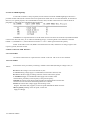
1
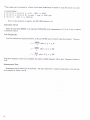
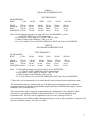
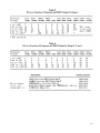
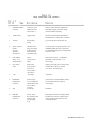
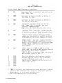
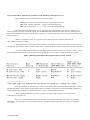
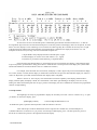
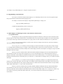
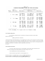
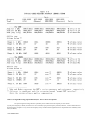
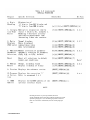
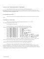
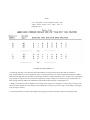
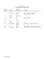
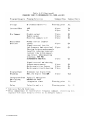
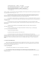
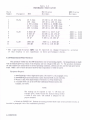
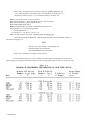
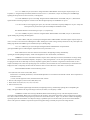
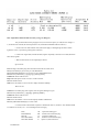
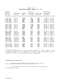
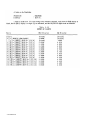
g. Similarly, with the inductance standards 1 mH, 100 mH, and 1 H, as indicated in the LS column, and with the indicated
measurement rate, verify that the RLC display is acceptable for each line of the table, for ranges 4,3,2, and 1.
5.8.6 D Measurement Accuracy
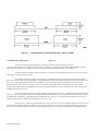
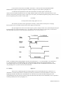
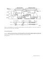
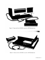
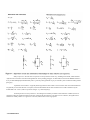
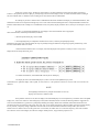
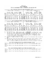
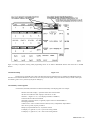
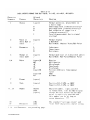
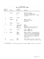
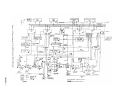
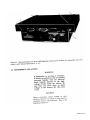
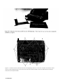
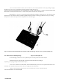
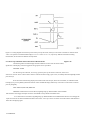
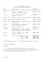
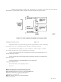
Figure 5-16.
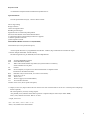
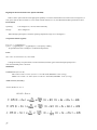
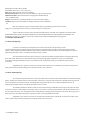
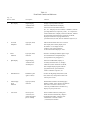
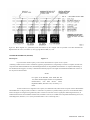
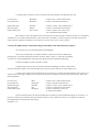
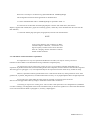
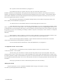
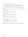
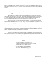
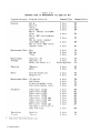
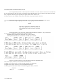
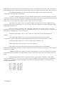
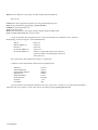
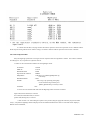
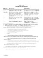
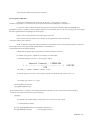
Verify D-measurement accuracy with the following procedure. Dissipation-factor checks will be made using
series equivalent circuit, with corresponding connections of resistance and capacitance standards.
This procedure follows after paragraph 5.8.5. (Thus, test frequency = 1 kHz, test voltage = 1 V, measure
rate = SLOW, range held indicator is NOT lit, and parameter L/Q is specified.)
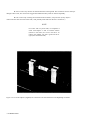
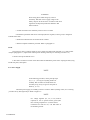
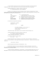
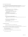
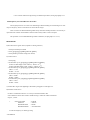
a. Connect the 1657-9600 extender cable to the Digibridge remote test fixture. Hand tighten the screws, to
provide ground (guard) connection.
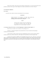
b. Connect the "high" leads (red and red/white) together and separately connect the "low" leads (black and
black/white) together.
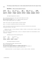
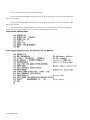
c. Press [FUNCTION] key to select ENTER function. To select 100 Hz, press
[.][1][=][SHIFT][FREQUENCY].
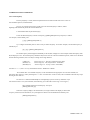
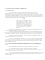
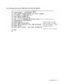
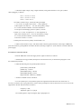
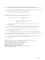
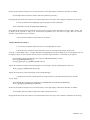
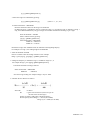
d. Before measurement, zero the Digibridge as follows:
Open Circuit.
Keep the "high" banana-plug stack separated from the "low" stack.
Press [FUNCTION] key (if necessary) to select MEASURE function.
Press [MEASURE MODE] key (if necessary) to select TRIGGERED mode.
Press these keys deliberately [1][][][8][9][=][SHIFT][OPEN].
Confirm that the GO indicator is lit.
Keep hands and objects at least 10 cm (4 in.) from test fixture.
Press the START button.
SER\'1CE 5-47