1
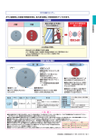
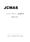
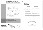
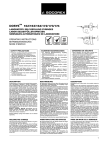
Service Manual
for scrubber drier
41 B 57
English
IP Gansow GmbH
Dreherstraße 9
59425 Unna
www.gansow.de
[email protected]
Tel.: 0049 (0)2303 2580-0
Rev 1.0
Translation of the
Original operating instructions
for scrubber drier
models 31 - 41 - 61 - 71 - 91 - 101 - 121 - 131 B / BF
IP Gansow GmbH
Dreherstraße 9
D 59425 Unna
Tel.: 0049 2303 2580-0
[email protected]
www.gansow.de
INDEX:
1.
IMPORTANT WARNINGS……………………………………
3
2.
INSTRUCTIONS BEFORE OPERATING……………………
5
3.
PRACTICAL GUIDE FOR THE OPERATOR………………
6
4.
INSTRUCTIONS…………………….…………………….…
8
5.
TROUBLESHOOTING…………………….…………………
12
6.
CLEANING AND MAINTENANCE…………………….……
15
7.
OPTIONAL ACCESSORIES…………………….……………
16
8.
CE CONFORMITY DECLARATION………..…….…………
17
9.
TECHNICAL SPECIFICATION…………………….…………
22
SPECIAL INFORMATION FOR
10. USING THE BATTERIES AND CHARGER…………………
23
CONTROL AND MAINTENANCE
11. OPERATIONS…………………….…………………….……
27
2 ENGLISH
1.
IMPORTANT WARNINGS:
1.1.
IMPORTANT! This appliance is not suitable for removing dusts
hazardous to health.
1.2.
IMPORTANT! This appliance is not suitable for washing carpet or
textile floors or wood floors not treated with non-absorbent resin.
1.3.
This appliance is not approved for use on public roads or highways.
1.4.
This appliance may only be used by personnel fully trained in its
correct and appropriate use.
1.5.
In order to prevent unauthorised use of the machine always remove
the key from the key switch before leaving the appliance unattended.
1.6.
Lower the brushes before leaving the machine unattended to prevent
accidental movement.
1.7.
When using the machine the operator should take care not to
endanger any third persons, particularly children.
1.8.
The appliance may not be used on slopes of greater than 2%.
1.9.
We expressly draw your attention to the fact that original parts and
accessories not supplied directly by Gansow have not been tested or
authorised by Gansow.
The installation and/or use of such items may therefore adversely
affect the efficiency and characteristics of your floor cleaning
machine, jeopardising its active and passive safety.
The manufacturer declines all liability for damage occurring as a
result of the use of non-original parts or accessories.
1.10.
Before any cleaning or servicing work is carried out on the machine,
the following precautions must be taken:
- unplug the plug from the charger from the charger socket;
- remove the key from the control panel.
ENGLISH 3
ATTENTION !
Before changing the main fuse, disconnect the battery cables from the
respective terminals (danger of short circuit).
1.11.
Under no circumstances may the charger leads (connecting the
charger to the machine) supplied be modified.
1.12.
All electrical functions of the machine are interrupted immediately as
soon as the plug is plugged into the charger socket.
1.13.
This appliance may be used with the brushes provided by the
producer only.
ATTENTION !
The safety of the appliance will be jeopardised by the use of other
brushes.
1.14.
*IMPORTANT - battery gas is highly explosive;
- avoid sparks or open flames close to the batteries!
To avoid the build-up of gas inside the machine, the tank and tank lid
must remain in the raised position throughout charging. The caps of
all battery cells must also be unscrewed and/or removed (not
necessary in the case of gel batteries).
1.15.
*IMPORTANT - battery acid is corrosive!
When topping up with distilled water make sure the level of liquid is
the same in all the battery cells. Dry cells shorten battery life and
may cause irreparable damage to the entire battery (not relevant to
gel batteries).
1.16.
IMPORTANT! Rooms where batteries are being charged should
always be well ventilated.
* Not relevant to maintenance free gel batteries
4 ENGLISH
2.
INSTRUCTIONS BEFORE OPERATING:
2.1.
Before operating a battery-powered machine, please read all the
following instructions and the instructions for use of the charger (if
purchased).
2.2.
Note that the batteries deliver maximum power only after eight to ten
charging cycles. During this period, the machine should not therefore
be used for excessively heavy cleaning.
2.3.
To provide your battery with even greater protection, the machine is
equipped with a charge indicator and hour counter.
By means of variously coloured LEDs (seven yellow and one red),
this provides a constant indication of the charge and automatically
shuts the brush motors down when the charge drops below the safety
level.
The LEDs indicate the following stages:
YELLOW ON: batteries within the charge limit
YELLOW FLASHING 15 seconds of running time remain before the brush
motors shut down.
RED ON: the battery is flat and the brushes are blocked. You should
immediately go to the charging area to avoid damaging the batteries.
The transition of one LED to another with a delay of just 15 seconds ensures
a prompt response in the event of flat batteries to avoid discharging them
further and therefore irreparably reducing their working life.
2.4.
IMPORTANT! The machine must not under any circumstances be
started up with the front and top lids raised.
ENGLISH 5
3.
3.1.
PRACTICAL GUIDE FOR THE OPERATOR:
*IMPORTANT - Seal the battery cells by screwing on the caps.
* Not relevant to maintenance free gel batteries
3.2.
After turning the charger off, unplug the connection lead from the
charger from the battery socket to power the machine.
3.3.
Lift the top lid and use a hose or bucket to fill the clean water tank (on
the left) with cold water up to a maximum of 3 cm from the top of the
tank (the water should preferably be cold and in any case never
hotter than 60°C).
IMPORTANT!
Use low foam detergent as excessive foam could
jeopardise the efficiency and function of the machine.
Close the top lid, lifting slightly on the hinge side to make sure it fits perfectly to
the tank.
IMPORTANT! If the lid does not fit perfectly, there would be no vacuum at
the squeegee and therefore no flow-back of liquid to the collection tank (on the
right). If necessary, repeat the operation correctly.
Avoid resting heavy objects on the lid as this could warp it and prevent it from
fitting perfectly to the tank.
3.4.
Make sure the cap of the dirty water tank (on the right) drain hose is
correctly in place. Perfect closure of the cap is essential to obtain a
vacuum in the collection tank and therefore maximum suction power.
3.5.
Turn the key switch clockwise to start the machine.
3.6.
Light pressure and a slight sideways movement of the pedal release
the brushes which are lowered in contact with the ground.
3.7.
To activate brush rotation, press the corresponding button on the left
side of the control panel.
MACHINES WITH DIAPHRAGM: Pressing this button opens the
water solenoid valve and turns the water pump on.
Turn the knob on the control panel clockwise to adjust the quantity
of water to the brushes (from 0 to 7 litres).
6 ENGLISH
MACHINES WITHOUT DIAPHRAGM: Pressing this button opens
the water solenoid valve.
To adjust the quantity of water to the brush in accordance with the
dirt to be removed (more dirt=more solution), use the red lever at
the bottom on the operator's right. When the lever is horizontal, the
cock is fully open, when vertical it is completely closed.
3.8.
Lower the squeegee to the ground, using the control lever in front of
the operator under the handle.
3.9.
Turn on suction to convey the dirty water to the collection tank, using
the button marked with a fan on the right of the control panel.
ENGLISH 7
4.
4.1.
INSTRUCTIONS:
SERIES "B" MODELS WITHOUT DRIVE:
The appliance is equipped with a patented drive system - as the
brush rotates in contact with the ground, it draws the whole machine
along at the correct working speed.
By pushing slightly, the drive speed can be increased as required.
Holding it back slows it down.
SERIES "BF" MODELS WITH DRIVE:
Push the drive lever gradually forwards to advance the machine at
the required speed. The maximum possible speed is 5.5 km/h.
On curves, adjust speed by moving the drive lever backwards.
When the lever is released completely, the drive motor stops
automatically.
ATTENTION!
The drive unit is fitted with a crush prevention device consisting of a
square red button at the centre of the handle which changes the
direction of movement if touched while the appliance is in reverse.
This prevents the operator being crushed in the event of incorrect
manoeuvres.
4.2.
Clean in parallel strips overlapping by 3 to 4 cm.
Rollers on the ends of the squeegee act as bumpers and also
enable you to clean at a tangent to the edges. The extreme
manoeuvrability of the squeegee which can be swung freely and
widely to both sides enables you to clean around any obstacle. The
squeegee then returns to the central position when the obstacle or
curve has been passed. When consigning the machine or during a
demonstration, our service technician can advise you on the best way
of cleaning your own particular floor surface.
4.3.
By means of a vacuum created inside the collection tank, the used
water and the dirt are completely absorbed and conveyed to the
dirty water tank.
To prevent dirty water or foam damaging the vacuum motor, the
collection tank is protected by two sensors (electrodes) which shut
8 ENGLISH
the machine down when the tank is full (they also detect the level of
any foam present).
4.4.
After finishing the work or when the solution in the tank is used up
(indicated with a red flashing light on the switch board), stop brush
rotation by pressing the corresponding button. This also stops the
flow of water. Raise the head using the pedal.
4.5.
To collect the remaining dirt, continue for a further 3-4 metres with
suction activated and the squeegee lowered, than turn both
functions off by pressing the suction button and raising the
squeegee lever. This empties all water left in the circuit into the
collection tank.
IMPORTANT!
After you have finished cleaning, you are recommended to raise the
tank lid and turn the suction motor on again for a few minutes. The
dry air sucked in will evaporate any remaining moisture, extending
the working life of the motor.
4.6.
Empty the collection tank into a container or drain using the black
drain hose and proceeding as follows:
-
4.7.
detach the hose from the control panel;
keeping the hose raised above the level of the tank at all times,
remove the cap;
lower the hose gradually towards the container.
IMPORTANT! After each cleaning session, you are recommended
to drain the dirty water and rinse the tank to avoid unpleasant
smells or the formation of harmful germs. To make this operation
faster, simpler and more effective, the appliance is fitted with
an exclusive system:
-
-
the tank tilts backwards, after raising the lid, lift the tank until it rests on
the chassis (empty before tilting);
after removing the cap, lower the drain hose to allow the water to run
off rapidly;
wash the collection tank with running water;
leave the tank tilted until the next time you use the machine.
The appliance has been designed to facilitate thorough maintenance.
A little attention improves the efficiency of your appliance and
extends the already long working life.
ENGLISH 9
4.8.
When parking the machine, you are recommended to lower the
brush head to anchor it to the ground.
4.9.
The machine has a rapid brush replacement system:
1- turn the key to the off position (anticlockwise as far as it will go),
2- use the pedal to lift the brush head,
3- hold the brush with both hands and turn it sharply in the normal
direction of rotation. In the case of heads with two motors, the
direction of rotation is always towards the centre of the head.
Hold the bayonet coupling firmly in position and release the
brush.
4- remove the brush and position the replacement in the centre of
the housing, precisely under the bayonet coupling,
5- use the pedal to raise the brush head,
6- switch the appliance on and activate brush rotation for a few
moments, then turn off again,
7- finally, raise the brush head and make sure the brush is correctly
fitted. If necessary, repeat operations 1 to 6.
4.10.
The key switch should be turned off before recharging the batteries.
4.11.
In order to avoid any build-up of gas inside the machine, the tank
(previously emptied) covering the batteries must be raised and
remain in that position throughout charging. Similarly, the caps of all
battery cells must also be unscrewed and/or removed (not
necessary in the case of maintenance-free gel batteries).
PRECAUTIONS
Battery gas is highly explosive. Avoid sparks and open flames near
the batteries.
When topping up with distilled water make sure the level of liquid is the
same in all the battery cells. Dry cells shorten battery life and may cause
irreparable damage to the entire battery (not relevant to maintenance-free
gel batteries).
10 ENGLISH
ATTENTION!
If the battery is damaged, the acid is highly corrosive!
4.12.
IMPORTANT! Rooms where batteries are being charged should
always be well ventilated.
Before using battery-powered models, read carefully the instructions
on use and maintenance of the machine, batteries and charger;
procedures and precautions to be observed while charging batteries
and connecting the charger and inspection and maintenance of
batteries and maintenance schedules.
ENGLISH 11
5. TROUBLESHOOTING:
5.1.
No water is delivered, check that:
-
5.2.
the brush is moving,
if necessary, activate the brush by using the button on the left of the
control panel,
there is water in the tank and the level is above the filter (the red LED
on the switch board is flashing),
if necessary, top up and add detergent,
the clean water filter is not clogged,
if necessary, remove and clean with air from the outside inwards,
the water solenoid valve is operating correctly,
if necessary, remove and clean,
the water cock is open (lever horizontal = fully open, lever vertical =
fully closed),
the knob on the control panel (diaphragm machines only) is not on
zero.
The water flow does not stop:
-
5.3.
close the water cock, then remove the solenoid valve and thoroughly
clean the inside, including the closure spring housing,
open the cock again and check it works,
replace the valve if necessary.
The suction motor does not start:
-
reset by using the key switch to turn the appliance off then on again,
-
clean the collection tank around the sensor electrodes and the
electrodes themselves.
ATTENTION!
Do not move the electrodes from their original position. Make sure
they are not already out of position. By modifying the distance
between them, or between the electrodes and the side of the tank, the
power cut-off mechanism may be activated by mistake. Contact the
Gansow Distributor Technical Assistance Service if necessary.
-
check the main fuse.
-
check the charge of the batteries and if necessary, charge.
12 ENGLISH
5.4.
Water is not sucked up, although the motor is operating;
-
-
5.5.
make sure the cap is correctly in place on the drain hose.
make sure the suction hose between the squeegee and the dirty water
tank is not blocked. If necessary unblock and fix the hose well to both
connecting pieces.
make sure the top lid is correctly in place on the tank, raise and lower
as described in point 3.3,
check the batteries are not flat.
The squeegee leaves wet marks or stripes:
-
-
clean the blades of the squeegee and remove any trapped grit or
paper,
check the wear of the squeegee blades and if necessary, turn or
replace,
PARABOLIC SQUEEGEE: make sure that when moving forwards with
suction on, the squeegee is perfectly horizontal. If necessary, adjust
the central nuts.
carry out the checks described in point 5.4.
IMPORTANT!
When dealing with large amounts of fluff, this may accumulate under
the rear squeegee blade causing leakage and therefore preventing
perfect drying. If this occurs, the squeegee should be raised while at
the same time moving the machine backwards to pick up the dirt left
on the ground, proceeding in a diagonal direction.
5.6.
The squeegee sticks to the floor due to strong suction:
-
-
-
check the state of the front blade and in particular the inlet slits. If
obstructed or worn, clean or enlarge them slightly, or cut one to three
additional slits until the squeegee functions correctly,
turn round or replace excessively worn squeegee blades. They can be
reversed to extend the working life,
STRAIGHT SQUEEGEE: adjust pressure on the ground using the
screw on the mobile support, tightening lightens the pressure,
unscrewing increases pressure.
PARABOLIC SQUEEGEE: adjust pressure on the ground by
tightening the adjustment nuts above the levelling wheels on the back
of the squeegee.
ENGLISH 13
5.7.
The brush motor shuts down:
-
5.8.
the automatic battery protection device has tripped. Stop working and
recharge the batteries immediately.
The dirty water does not drain out through the hose:
-
5.9.
make sure the tank is not blocked near the drain outlet.
remove any blockages in the drain hose itself.
The machine leaves a smeary mark:
-
5.10.
-
-
14 ENGLISH
no water flow,
no solution in the tank (fill the tank), or solution tank filter dirty (clean
filter),
check the brush feed pipe which could be blocked,
open the water cock if closed.
carry out the additional checks described in point 5.1.
The machine does not move forward or moves forward too
slowly (BF SERIES MODELS WITH DRIVE ONLY)
check and remove any oxidation on the battery terminals, then tighten,
the squeegee is stuck to the ground by excessive suction. See point
5.6.
the batteries are flat, stop work and recharge.
6. SERVICE AND MAINTENANCE:
6.1.
Before any servicing or maintenance work is carried out on the
machine and before any parts are replaced:
-
-
drain both tanks completely,
unplug the plug from the charger from the charger socket,
turn off the key switch.
6.2.
The electrodes in the dirty water tank should always be kept
clean and in their original position. By modifying the distance
between them, or between the electrodes and the tank, the
power cut-off mechanism may not activate correctly.
6.3.
Clean the dirty water tank thoroughly and regularly to prevent the
formation of unpleasant odours and bacteria. Tilt the tank to
facilitate cleaning.
6.4.
The tank lid should always be left open between cleaning
sessions to enable the internal surface to dry out. Never place
heavy objects on the top lid as this could warp it.
6.5.
After each cleaning session, clean the outside of the machine to
remove any chemical residues which could accelerate wear and
affect the appearance of the materials.
6.6.
The filter in the clean water tank should be cleaned regularly
twice a week.
6.7.
Check the state of the squeegee blades regularly and if
necessary turn them over or replace them. See also sections 5.5.
and 5.6.
6.8.
Perform battery maintenance regularly to maintain their efficiency
and extend their working life. They are expensive and should be
kept in good condition.
6.9.
The outlet slits on the suction motor should be checked and
cleaned regularly, especially where there is a considerable
amount of fluff in the atmosphere.
6.10.
A general control by authorised Gansow
recommended at least once every six months.
personnel
is
ENGLISH 15
7. OPTIONAL ACCESSORIES:
7.1.
Depending on the type of floor and dirt, you may want to use
brushes other than those supplied as standard.
The following are available from your Gansow Distributor:
- Black soft and PES brushes for delicate floors (gyms, sealed wood,
etc);
- in polycarbonate of various hardnesses for a more energetic and
deep treatment.
7.2.
As an alternative to the brushes, you can use a pad, available in
three versions with different colours:
-
-
black = abrasive
red/green/purple = medium hard
brown/yellow/white = soft.
The brush does not need to be removed to use the pad, which can be
fitted directly to the brush itself. Alternatively, a special pad holder can
be provided.
16 ENGLISH
8. TECHNICAL SPECIFICATION:
31 B 46/50
41 B/BF 53/57
61 B/BF 53/57
Cleaning width
mm
460/500
530/570
530/570
Squeegee width
mm
870
870
870
Capacity per hour theor.
m²/h
1840
2120/2930
2120/2930
Maximum speed
km/h
4
4/5,5
4/5,5
Number of brushes
no.
1
1
1
Brush diameter
mm
460
533
533
kg
24
31.5
31.5
g/cm2
110
109
109
rpm
180
200
200
W
600
650
650
-
Mechanical
B : MECHANICAL
BF : ELECTRONIC
B : MECHANICAL
BF : ELECTRONIC
Nominal drive motor
power
W
/
B:/
BF : 200
B:/
BF : 200
Suction motor power
W
350
410
550
Max. brush pressure
Pressure of brush head
on the ground
Brush rotation speed
Brush motor power
Drive
Sound pressure
dB(A)
83
83
83
Solution tank
l
26
40
62
Collection tank
l
26
40
62
Diaphragm
/
-
-
Yes
Drive wheel diameter
mm
160
230
230
Pivoting wheel diameter
mm
125
125
125
B : 135
BF : 148
Net weight without
batteries
kg
100
B : 129
BF : 142
Number of batteries
no.
2
2
2
V
24
24
24
Machine size
cm
X/Y/Z
124x51x95
128,5x60,5x108,5
143x60,5x108,5
128,5x60,5x113
143x60,5x113
Total oscillation value
m/s²
<2,5
<2,5
<2,5
Voltage of batteries in
series
ENGLISH 17
TECHNICAL SPECIFICATION:
61 B/BF 65/68
71 BF 70/72
Cleaning width
mm
71 BF 85
650/680
700/720
850
Squeegee width
mm
1000
1000
1150
Capacity per hour theor.
m²/h
2120/2930
3850
4675
Maximum speed
km/h
4/5,5
5,5
5,5
Number of brushes
no.
2
2
2
Brush diameter
mm
345
370
430
31,5
40
45
125
156
135
rpm
180
180
180
W
250
400
400
-
B : MECHANICAL
BF : ELECTRONIC
W
B:/
BF : 200
400
400
Max. brush pressure
Pressure of brush head
on the ground
Brush rotation speed
Brush motor power
Drive
Nominal drive motor
power
Suction motor power
Sound pressure
Solution tank
kg
g/cm
2
ELECTRONIC ELECTRONIC
W
550
550
550
dB(A)
83
82
82
l
62
70
70
Collection tank
l
62
70
70
Diaphragm
/
Yes
-
-
Drive wheel diameter
mm
230
230
230
Pivoting wheel diameter
mm
125
160
160
Net weight without
batteries
kg
B : 137
BF : 150
185
187
Number of batteries
no.
2
4
4
V
24
24
24
Machine size
cm
X/Y/Z
124x69x113
139x69x113
163x76x111
167x86x111
Total oscillation value
m/s²
<2,5
<2,5
<2,5
Voltage of batteries in
series
18 ENGLISH
TECHNICAL SPECIFICATION:
91 BF 70/72
91 BF 85
101 BF 70/72
700/720
850
700/720
1000
1150
1000
m²/h
3850
4675
3850
km/h
5,5
5,5
5,5
Cleaning width
mm
Squeegee width
mm
Capacity per hour theor.
Maximum speed
Number of brushes
no.
2
2
2
Brush diameter
mm
370
430
370
40
45
40
156
135
156
180
180
180
Max. brush pressure
Pressure of brush head
on the ground
Brush rotation speed
Brush motor power
Drive
Nominal drive motor
power
Suction motor power
kg
g/cm
2
rpm
W
400
400
400
-
ELECTRONIC
ELECTRONIC
ELECTRONIC
W
400
400
400
W
550
550
550
dB(A)
82
82
85
Solution tank
l
90
90
100
Collection tank
l
90
90
100
Diaphragm
/
Yes
Yes
Yes
Drive wheel diameter
mm
230
230
230
Pivoting wheel diameter
mm
125
125
160
Net weight without
batteries
kg
169
171
179
Number of batteries
no.
4
4
4
V
24
24
24
Machine size
cm
X/Y/Z
139x76x113
139x86x113
163x76x115,5
Total oscillation value
m/s²
<2,5
<2,5
<2,5
Sound pressure
Voltage of batteries in
series
ENGLISH 19
TECHNICAL SPECIFICATION:
101 BF 85
121 BF 70/72
Cleaning width
mm
121 BF 85
850
700/720
850
Squeegee width
mm
1150
1000
1150
Capacity per hour theor.
m²/h
4675
3850
4675
Maximum speed
km/h
5,5
5,5
5,5
Number of brushes
no.
2
2
2
Brush diameter
mm
430
370
430
45
40
45
135
156
135
180
180
180
Max. brush pressure
Pressure of brush head
on the ground
Brush rotation speed
Brush motor power
Drive
Nominal drive motor
power
Suction motor power
kg
g/cm
2
rpm
W
400
400
400
-
ELECTRONIC
ELECTRONIC
ELECTRONIC
W
400
400
400
W
550
550
550
dB(A)
85
82
82
Solution tank
l
100
120
120
Collection tank
l
100
120
120
Diaphragm
/
Yes
Yes
Yes
Drive wheel diameter
mm
230
230
230
Pivoting wheel diameter
mm
160
160
160
Net weight without
batteries
kg
181
194
196
Number of batteries
no.
4
4
4
V
24
24
24
Machine size
cm
X/Y/Z
167x86x115,5
163x76x115,5
167x86x115,5
Total oscillation value
m/s²
<2,5
<2,5
<2,5
Sound pressure
Voltage of batteries in
series
20 ENGLISH
TECHNICAL SPECIFICATION:
101 BF 70/72 S
101 BF 85 S
131 BF 100 S
700/720
850
1000
1000
1150
1150
m²/h
3850
4675
5500
km/h
5,5
5,5
5,5
Cleaning width
mm
Squeegee width
mm
Capacity per hour theor.
Maximum speed
Number of brushes
no.
2
2
2
Brush diameter
mm
370
430
370
40
45
54
270
225
240
180
180
180
Max. brush pressure
Pressure of brush head
on the ground
Brush rotation speed
Brush motor power
Drive
Nominal drive motor
power
Suction motor power
kg
g/cm
2
rpm
W
600
600
600
-
ELECTRONIC
ELECTRONIC
ELECTRONIC
W
850
850
1100
W
550
550
660
dB(A)
83
83
85
Solution tank
l
100
100
130
Collection tank
l
100
100
130
Diaphragm
/
Yes
Yes
Yes
Drive wheel diameter
mm
250
250
250
Pivoting wheel diameter
mm
160
160
160
Net weight without
batteries
kg
212
221
268
Number of batteries
no.
4
4
6
V
24
24
36
Machine size
cm
X/Y/Z
163x76x115,5
167x86x115,5
168x102x115,5
Total oscillation value
m/s²
<2,5
<2,5
<2,5
Sound pressure
Voltage of batteries in
series
ENGLISH 21
9.
CE CONFORMITY DECLARATION
We hereby declare that the machine described below complies with the
relevant basic safety and health requirements of the EU Directives, both in
its basic design and construction as well as in the version put into
circulation by us. This declaration shall cease to be valid if the machine is
modified without our prior approval.
Product:
Floor cleaner
Type:
Premium Green Line
Relevant EU Directives
2006/42/CE
2004/108/CE
2000/14/CE
Applied harmonized standards
EN 50106:2009-07-01
EN 55014-1: 2007-06
Applied national standards
DIN EN 60335-1: 2007-02
DIN EN 60335-2-72
DIN EN 60529: 1991 + A1: 2000
The undersigned act on behalf and under the power of attorney of the
company management.
___________
R. Mimmler
H. Waschke
Technical Director
Product Standard Compliance
IP Gansow GmbH
Dreherstraße 9
59425 Unna
Tel.: +49 (0)2303 2580 0
Fax: +49 (0)2303 2580 199
22 ENGLISH
10.
SPECIAL INFORMATION FOR USING THE BATTERIES
AND CHARGER
Do you know how much a set of batteries costs?
Between about 650 and 2000 € according to the size of your machine.
Should you have armoured tube batteries, the cost of a set is between
2500 and 2100 €.
Reason enough, we think, to give these expensive energy units the
necessary daily attention required, in order to achieve the greatest possible
working life from them.
To ensure even greater protection for your batteries, we stock a battery
condition indicator which shows the state of the battery at any given time.
This instrument (type: BEM) is a panel type and can be fitted in the panel
on any of our battery-powered machines.
Luminous diodes of various colours are used to indicate the different levels
of voltage. The device can also be used to switch the brush motor(s) off
automatically as soon as the battery reaches an fix state of discharge.
Please feel free to consult the staff at our local sales depots or dealers for
information on using and fitting these instruments as well as on the way
they work.
Points you really must take notice of:
- Never discharge the batteries too low.
Every battery should only be discharged to 70 or 80% of its rated capacity.
You will overburden the batteries,
a)
if you use your machine too long, too often. How long you can
safely work your machine, will be explained to you, when our
service personnel installs your equipment.
You can ask our service personnel at any time, or call our nearest
service depot. For machines fitted with a BEM the brushes will
automatically be switched off when the battery voltages becomes
too low.
ENGLISH 23
b)
if you use your machine regularly more than once within 24 hours
to a certain extend. A good battery charger requires continuously
approx. 10 - 12 hours (according to type) to recharge empty
batteries. If you interrupt the charging process, the batteries will
never become fully charged, and will be quickly ruined.
c)
if you do not recharge the batteries immediately after having used
them to about 70 or 80% of their rated capacity. Empty batteries do
not have the power for a further operation, and will be quickly
ruined. For machines fitted with a BEM the brushes will
automatically be switched off when the battery voltages becomes
too low.
If you use your machine daily for (a) short period(s) only, ask at
your nearest agency, or our service personnel. We will inform you
as to the most practical way to use your charger to avoid premature
corrosion of the battery.
- Storage of batteries
f batteries are taken out of service for a lengthy period they should
be stored fully charged in a dry, frost-free room. To ensure the
battery is always ready for use a choice of charging methods can be
made:
a)
A quarterly full charge.
If loads are connected, e.g. BEM, a full charge could be needed after 3
weeks.
b)
Float charging at the instructed charging voltage.
- Correct connection of the battery charger.
Please take careful note that:
d)
e)
f)
the plug of the charger cable is firmly plugged into the machine;
the mains plug is firmly fitted into the wall socket. Confirm that the
wall socket has electrical feed overnight and hang a notice on the
plug, saying, that during the charging period the plug, must not be
removed;
the battery charger will switch itself on automatically after 15
seconds.
24 ENGLISH
Before leaving the machine, please check carefully, that all connections are
properly made and that the charger is switched on. Many batteries have
been damaged prematurely because something has been overlooked.
Please read the operating instructions of the type of charger in use with
you.
- Secure seating of the post terminals on the cables, that join the
batteries together.
Loose battery post terminals are dangerous because a layer builds up that
hinders the flow of electricity. When recharging the batteries, full electrical
charge cannot flow, the batteries will not become fully charged and are
therefore damaged prematurely. Should you find loose post terminals,
please do not simply tighten them, but remove them, clean the post and the
terminal inside and out, smear with battery grease and refit tightly.
- Run-in instruction
Note that brand-new batteries need a running-in period and thus can not
yet supply full power during the first 8 - 10 discharges. Therefore, the
machine should be kept off heavy duty jobs during that time.
Should you have any further questions about the handling of your battery
machine, please call our nearest office or agency.
- *Never let the batteries get dry.
The electrolyte must cover the cell plates at all times, it should be at least
5/8 ths of an inch over the plates. Cell plates that are continuously dry or
part dry, build up a layer that prevents the cells from charging, rendering
the battery useless within a short time.
- *Never overfill the batteries.
Too much electrolyte is as bad as too less. Only top up to approx. 5/8 ths of
an inch above the cell plates.
Important in breaching with battery acid - corrosive!
- *Always top up the batteries with distilled water, never acid.
The only thing that vaporises when the batteries are warm, is the distilled
water, therefore it is only necessary to top up with distilled water. Topping
up with acid, makes the electrolyte too strong, and causes corrosion on the
cell plates.
Important in breaching with battery acid - corrosive!
*this does not apply to maintenance-free batteries
ENGLISH 25
- *Never top up with tap water.
Tap water has an electrical conductivity and will destroy the batteries. You
can purchase distilled water at Electrical Wholesalers, from us, or from
Petrol Stations.
If you have any further questions about the handling of our battery
machines then please contact your nearest Gansow representative or our
head quarter in Unna / Germany.
*this does not apply to maintenance-free batteries
26 ENGLISH
11.
CONTROL AND MAINTENANCE OPERATIONS:
IMPORTANT!
Repairs should preferably be performed by qualified personnel.
Only original spare-parts may be used. Modification of the machine without
the approval of the manufacturer or the use of unauthorised materials
invalidates the warranty as the structural condition of the machine may differ
from that described in the certificate
After any repair work by unauthorised personnel the machine must be
officially approved by Gansow or a technician authorised by the company
to confirm conformity with the original conditions and therefore the validity
of the general terms of the warranty.
Before any cleaning or servicing work is carried out on the machine,
disconnect the charger cable and remove the key from the key switch to
guarantee operator safety.
IMPORTANT SAFEGUARDS
The following tasks should be carried out daily before or after each
work session:
-
-
remove dirty water and rinse out the tank,
clean the machine (do not use water jets or water cleaners)
rinse the suction hose by running water from inside the tank,
charge battery and check that the battery terminals and power plug are
securely in position
clean the electrodes and check the level of the dirty water and foam,
make sure the tank lid fits correctly to the tank.
ENGLISH 27
Table of recommended checks, inspections and maintenance and
schedule, based on daily use of about four hours;
Description of control
1. General controls
Check the fixing and condition of the brush
Check for water leaks from the tanks
Clean the solution tank filters
Make sure the switches and indicator lights
on the panel are working correctly
Check that the squeegee blades are not
worn or damaged
Check that the squeegee is correctly
adjusted and adheres to the ground when
suction is activated
Grease the head raising and squeegee
lever rotation pins
Make sure there are no foreign bodies in the
drive wheels and check the tyres are not
worn
2. Motors
Check, if possible, wear of the drive motor
carbon brushes and replace if necessary
Check wear of the brush motor carbon
brushes and replace if necessary (battery
powered models only)
Check wear of the suction motor carbon
brushes and replace if necessary
3. Drive
Ensure cables are not damaged or loose
28 ENGLISH
interval interval interval interval interval
WK.LY MTH.LY 4/MTH 6/MTH YR.LY
X
X
X
X
X
X
X
X
X
X
X
X
Description of controls
4. Collection tank
Make sure the drain hoses are not blocked
Make sure the suction hose is not blocked
5. Batteries
Check the condition of the cables and the
seal of the cell caps.
If the machine is not used and the batteries
are active, recharge every three months
Top up the level of battery fluid in all cells.
(not necessary with gel batteries)
Grease the battery terminals (not necessary
with gel batteries).
Call the authorised Gansow technical
assistance service for a full control
interval interval interval interval interval
WK.LY MTH.LY 4/MTH 6/MTH YR.LY
X
X
X
X
X
X
X
IP Gansow GmbH
Dreherstraße 9
59425 Unna
www.gansow.de
[email protected]
Tel.: 0049 (0)2303 2580-0
ENGLISH 29
85613
MODELL/MODEL: 41 B 57
VERKLEIDUNG/COVER
10
06
01
02
07
05
08
13
19
14
24
20
21
22
23
25
16
59
26
17
62
56
12
09
03
57
BLATT/PAGE: 01
18
15
04
58
11
DATUM/DATE: 01/2011
63
36
64
37
38
61
60
50
51
52
53
55
35
39
28
27
29
49
48
47
46
40
41
34
30
42
54
45
44
43
33
32
31
85613
41 B 57
Position
0001
0002
0003
0004
0005
0006
0007
0008
0009
0010
0011
0012
0013
0014
0015
0016
0017
0018
0019
0020
0021
0022
0023
0024
0025
0026
0027
0028
0029
0030
0031
0032
0033
0034
0035
0036
0037
Menge Artikel-Nr.
IPC
Bezeichnung
1
05328
VTVT00173 Schraube, Senkkopf-, M 6 x 25
2
05096
VTDD00482 Mutter, Sechskant, M 6
1
01728
LAFN01252 Stütze, Aufstell-, für vorderen Deckel
1
05119
VTRS00041 Scheibe, Unterleg-, M 6
1
05218
VTDD86633 Mutter, Sechskant-, selbstsichernd, M 6
1
05218
VTDD86633 Mutter, Sechskant-, selbstsichernd, M 6
2
05119
VTRS00041 Scheibe, Unterleg-, M 6
1
05119
VTRS00041 Scheibe, Unterleg-, M 6
1
05012
VTVT00444 Schraube, Sechskant, M 6 x 20
4
05503
VTVT14095 Schraube, Zylinderkopf-, M 6 x 16
4
01693
LAFN01250 Hülse, Distanz-, 8 x 3 mm
8
05119
VTRS00041 Scheibe, Unterleg-, M 6
2
14278
CEVR00018 Deckelscharnier, 80 x 80 x 1,5 mm
4
05119
VTRS00041 Scheibe, Unterleg-, M 6
4
05217
VTDD00026 Mutter, Sechskant-, selbstsichernd, M 5
4
05557
VTRS00067 Rosette, M 5, schwarz
4
05065
Schraube, Linsensenkkopf-, M 5 x 18
1
05218
VTDD86633 Mutter, Sechskant-, selbstsichernd, M 6
2
05119
VTRS00041 Scheibe, Unterleg-, M 6
1
13449
CMCV00071 Seil, Edelstahl-, für oberen Deckel
1
05119
VTRS00041 Scheibe, Unterleg-, M 6
1
05259
VTVT01531 Schraube, Sechskant, M 6 x 16
1
31215
Aufkleber, Keil, grün, rechts, 41/61/91 B/BF
1
31216
Deckel, oberer-, grün, 41 B/BF
1
06925
MEVR00331 Deckel für Sicherungsautomaten
1
31217
Platte, Abdeck-, am Gestell, 41/61 B/BF
1
05461
VTVT00184 Schraube, Selbstschneidend, M 5 x 16
1
05557
VTRS00067 Rosette, M 5, schwarz
1
31214
Aufkleber, Keil, grün, links, 41/61/91 B/BF
30
05157
VTVR00073 Niete, Blind-, 4 x 12
2
31218
Aufkleber, grün, 41 B 57
1
31219
Seitenverkleidung, links, 41/61/91 B/BF
1
24002
Gestell, 41/61 B/BF
1
31220
Seitenverkleidung, rechts, 41/61/91 B/BF
1
02451
LAFN01276 Hebel für Bürstenkopf, 41/61 B/BF
1
05209
VTVT00158 Schraube, Zylinderkopf-, M 10 x 25
1
05133
VTRS01081 Federring, M 10
Blatt/Page 1
Verkleidung-Cover
Description
countersunk head screw, M 6 x 25
hexagonal screw, M 6
support for front lid
washer, M 6
hexagonal nut, selfsealing, M 6
hexagonal nut, selfsealing, M 6
washer, M 6
washer, M 6
hexagonal screw, M 6 x 20
allen cap screw, M 6 x 16
spacer sleeve, 8 x 3 mm
washer, M 6
hinge for top lid, 80 x 80 x 1,5 mm
washer, M 6
hexagonal nut, selfsealing, M 5
collar, M 5, black
raised countersunk head screw, M 5 x 18
hexagonal nut, selfsealing, M 6
washer, M 6
cable rope for top lid
washer, M 6
hexagonal screw, M 6 x 16
sticker, wedge form,gr.,right, 41/61/91 B/BF
top lid, green, 41 B/BF
lid for automatic cut-out
cover at the frame, 41/61 B/BF
self tapping screw, M 5 x 16
collar, M 5, black
sticker, wedge form,gr.,left, 41/61/91 B/BF
rivet, 4 x 12 mm
sticker, green, 41 B 57
side cover, left, 41/61/91 B/BF
frame, 41/61 B/BF
side cover, right, 41/61/91 B/BF
brush head lever, 41/61 B/BF
allen cap screw, M 10 x 25
spring washer, M 10
bis / up to
ab / from
85613
MODELL/MODEL: 41 B 57
VERKLEIDUNG/COVER
10
06
01
02
07
05
08
13
19
14
24
20
21
22
23
25
16
59
26
17
62
56
12
09
03
57
BLATT/PAGE: 01
18
15
04
58
11
DATUM/DATE: 01/2011
63
36
64
37
38
61
60
50
51
52
53
55
35
39
28
27
29
49
48
47
46
40
41
34
30
42
54
45
44
43
33
32
31
85613
0038
0039
0040
0041
0042
0043
0044
0045
0046
0047
0048
0049
0050
0051
0052
0053
0054
0055
0056
0057
0058
0059
0060
0061
0062
0063
0064
Verkleidung-Cover
41 B 57
1
2
1
1
1
1
2
1
1
1
1
1
1
5
5
5
1
1
1
2
1
2
1
1
1
2
1
05116
05114
24003
05116
05016
01786
05126
01677
05103
05303
05116
05116
05219
05058
05557
05217
31221
16597
05038
05117
05098
05446
14841
05098
13449
05446
05217
VTRS00505
VTRS00040
LAFN01392
VTRS00505
VTVT00141
VTVR00062
VTRS00506
VTVR00061
VTDD01682
VTVT00167
VTRS00505
VTRS00505
VTDD00027
VTVT00146
VTRS00067
VTDD00026
VTRS00502
VTDD01678
VTRS00056
CEVR00021
VTDD01678
CMCV00071
VTRS00056
VTDD00026
Scheibe, Unterleg-, M 10
Scheibe, Unterleg-, 12 x 18 x 1 mm
Verbindungslasche Bürstenk., 41/61 B/BF
Scheibe, Unterleg-, M 10
Schraube, Sechskant, M 10 x 30
Bolzen mit Kopf, 12 x 55 mm
Scheibe, Unterleg-, M 12
Federstecker, 3,2 mm
Mutter, Sechskant, M 12
Schraube, Zylinderkopf-, M 12 x 40
Scheibe, Unterleg-, M 10
Scheibe, Unterleg-, M 10
Mutter, Sechskant-, selbstsichernd, M 10
Schraube, Linsensenkkopf-, M 5 x 14
Rosette, M 5, schwarz
Mutter, Sechskant-, selbstsichernd, M 5
Deckel, vorderer-, grün, 41/61 B/BF
Aufkleber, Limette
Schraube, Zylinderkopf-, M 5 x 30
Scheibe, Unterleg-, M 5
Mutter, Sechskant, M 5
Scheibe, Unterleg-, 5 x 15 mm
Scharnier für vorderen Deckel, 340 mm
Mutter, Sechskant, M 5
Seil, Edelstahl-, für oberen Deckel
Scheibe, Unterleg-, 5 x 15 mm
Mutter, Sechskant-, selbstsichernd, M 5
Blatt/Page 2
washer, M 10
washer, 12 x 18 x 1 mm
connection link, 41/61 B/BF
washer, M 10
hexagonal screw, M 10 x 30
bolt with head, 12 x 55 mm
washer, M 12
spring clip, 3,2 mm
hexagonal screw, M 12
allen cap screw, M 12 x 40
washer, M 10
washer, M 10
hexagonal nut, selfsealing, M 10
raised countersunk head screw, M 5 x 14
collar, M 5, black
hexagonal nut, selfsealing, M 5
front lid, green, 41/61 B/BF
sticker, lime
allen cap screw, M 5 x 30
washer, M 5
hexagonal screw, M 5
washer, 5 x 15 mm
hinge for front lid, 340 mm
hexagonal screw, M 5
cable rope for top lid
washer, 5 x 15 mm
hexagonal nut, selfsealing, M 5
85613/85615/85616
MODELL/MODEL: 41/61 B 57/68
GESTELL/FRAME
DATUM/DATE: 01/2011
01
02
03
04
05
06
13
12
14
15
16
11
10
09
08
07
BLATT/PAGE: 02
85613
Position
0001
0002
0003
0004
0005
0006
0007
0008
0009
0010
0011
0012
0013
0014
0015
0016
Gestell-Frame
41 B 57
Menge Artikel-Nr.
1
24002
1
14330
4
75258
4
75057
4
05136
4
05094
2
75067
2
05296
2
05127
2
16826
4
75133
1
24004
3
05075
3
75057
3
05136
3
05094
IPC
RTRT00063
VTVT00326
VTRS63243
VTRS01080
VTDD10776
VTVT00243
VTRS00071
VTRS00044
VTRS00116
VTVT00155
VTRS63243
VTRS01080
VTDD10776
Bezeichnung
Gestell, 41/61 B/BF
Lenkrolle, 125 mm
Schraube, Schloss-, M 8 x 30
Scheibe, Unterleg-, 8 x 24 mm
Federring, M 8
Mutter, Sechskant-, M 8
Schraube, Sechskant-, M 6 x 16
Federring, M 6
Scheibe, Unterleg-, 6 x 30 mm
Rad, 230 mm
Scheibe, Unterleg-, 12 x 24 mm
Achse mit Grundplatte, 41/61 B
Schraube, Schloss-, M 8 x 25
Scheibe, Unterleg-, 8 x 24 mm
Federring, M 8
Mutter, Sechskant-, M 8
Blatt/Page 3
Description
frame, 41/61 B/BF
caster wheel, 125 mm
carriage bolt, M 8 x 30
washer, 8 x 24 mm
spring washer, M 8
hexagonal nut, M 8
hexagonal screw, M 6 x 16
spring washer, M 6
washer, 6 x 30 mm
wheel, 230 mm
washer, 12 x 24 mm
axle with base plate, 41/61 B
carriage bolt, M 8 x 25
washer, 8 x 24 mm
spring washer, M 8
hexagonal nut, M 8
bis / up to
ab / from
85613
MODELL/MODEL: 41 B 57
WASSERTANK/TANK
DATUM/DATE: 01/2011
BLATT/PAGE: 03
26
40
41
24
25
27
33
34
23
15
18
19
17
16
22
28
21
20
30
29
42
35
36
37
38
32
31
45
39
14
46
47
48
12
51
13
11
12
10
09
08
06
05
04
03
02 01
07
67
66
60
65
64
43
61
63
62
59
58
57
56
55
54
53
52
50
49
44
85613
Position
0001
0002
0003
0004
0005
0006
0007
0008
0009
0010
0011
0012
0013
0014
0015
0016
0017
0018
0019
0020
0021
0022
0023
0024
0025
0026
0027
0028
0029
0030
0031
0032
0033
0034
0035
0036
0037
Wassertank-Tank
41 B 57
Menge Artikel-Nr.
IPC
Bezeichnung
4
05359
MPVR60346 Abedckkappe, Kunststoff-, M 6
4
05241
VTVT06238 Schraube, Sechskant, M 6 x 35
4
05123
VTRS00043 Scheibe, Unterleg-, M 6
4
05120
VTRS00042 Scheibe, Unterleg-, M 8
4
05350
VTRS00052 Schraubensicherungsring, M 6
4
05120
VTRS00042 Scheibe, Unterleg-, M 8
4
05123
VTRS00043 Scheibe, Unterleg-, M 6
4
05131
VTRS01079 Federring, M 6
4
05096
VTDD00482 Mutter, Sechskant, M 6
1
30219
LAFN01524 Haube für Saugmotor, 41 B/BF
1
04043
PMVR00449 Motor, Saug-, 24 V, 2-stufig, komplett
2
01448
GUVR00027 Dichtungsring für Turbine
1
11114
MOMO00015 Motor, Saug-, 24 V, 2-stufig
2
06463
MEVR00199 Hülse, Aderend-, 2,5 mm²
2
05321
Schraube, Senkkopf-, M 6 x 20
2
75168
VTRS00118 Rosette, M 6, schwarz
1
30175
MPVR01135 Haube, Abdeck-, für Elektroden
2
05218
VTDD86633 Mutter, Sechskant-, selbstsichernd, M 6
6
06365
FSVR00015 Abbinder
6
14733
Abbinderhalter
1
06724
MEVR00239 Elektrodenkabel
2
06784
MEVR00257 Rundsteckhülsen, PIDG-NYL
2
01733
MEVR00161 Verschraubung-, Kabel-, PG 7
2
13382
GUVR00034 Elektrodendichtung
1
40985
DBDB00918 Elektroden, Satz
1
31213
Tankdichtung, Green Line, Meterware
2
05238
Blindniete, 3 x 14 mm
1
13458
RCVR00120 Kappe, Abdeck-, 51 mm, schwarz
1
04374
MPVR01049 Sieb, komplett, 130 mm
1 HT1020
MPVR04735 Klappe im SW-Tank
2
01620
RCVR00088 Rohrbogen, 90 Grad, 40 mm, PVC
1
31222
Tank, 41 B/BF
4
05221
VTDD36474 Mutter, Hut-, M 8
4
05121
VTRS17677 Scheibe, Unterleg-, M 10
4
05351
VTRS00053 Schraubensicherungsring, M 8
2
02060
CEVR00016 Tankscharnier
4
05118
VTRS00503 Scheibe, Unterleg-, M 8
Blatt/Page 4
Description
cap for hexagonal nut, M 6
hexagonal screw, M 6 x 35
washer, M 6
washer, M 8
packing ring, plastic, M 6
washer, M 8
washer, M 6
spring washer, M 6
hexagonal screw, M 6
cover for suction motor, 41 B/BF
suction motor, 24 V, 2-stages, complete
sealing ring for suction motor
suction motor, 24 V, 2-stages
cable end, 2,5 mm²
countersunk head screw, M 6 x 20
collar, M 6, black
probe cover
hexagonal nut, selfsealing, M 6
cable strap
holder for cable strap
probe cable
socket, PIDG-NYL
probe holder, PG 7
probe sealing
probe, set
sealing for tank, Green Line, by the meter
Rivet, 3 x 14 mm
cover, 51 mm, black
filter, complete, 130 mm
plate inside the dirt water tank
elbow, 90 degree, 40 mm, PVC
tank, 41 B/BF
cap nut, M 8
washer, M 10
packing ring, plastic, M 8
tank hinge
washer, M 8
bis / up to
ab / from
85613
MODELL/MODEL: 41 B 57
WASSERTANK/TANK
DATUM/DATE: 01/2011
BLATT/PAGE: 03
26
40
41
24
25
27
33
34
23
15
18
19
17
16
22
28
21
20
30
29
42
35
36
37
38
32
31
45
39
14
46
47
48
12
51
13
11
12
10
09
08
06
05
04
03
02 01
07
67
66
60
65
64
43
61
63
62
59
58
57
56
55
54
53
52
50
49
44
85613
0038
0039
0040
0041
0042
0043
0044
0045
0046
0047
0048
0049
0050
0051
0052
0053
0054
0055
0056
0057
0058
0059
0060
0061
0062
0063
0064
0065
0066
0067
Wassertank-Tank
41 B 57
4
4
1
1
4
4
4
1
2
2
1
4
4
4
4
4
4
4
4
4
4
4
4
2
1
2
2
2
2
1
05136
05250
31245
31246
05117
05130
05319
40952
13254
13261
21345
05218
05123
05119
05119
05099
05123
05120
05350
05120
05123
05017
05359
05327
03515
05351
05121
05242
05221
VTRS01080 Federring, M 8
VTVT00449 Schraube, Sechskant, M 8 x 35
Buchse, 9-Polig
Stecker, 9-Polig
VTRS00502 Scheibe, Unterleg-, M 5
VTRS08013 Federring, M 5
VTVT00170 Schraube, Zylinderkopf-, M 5 x 8
PMQE00150 Lenkgriff, 41/61 B
VTVR00086 Mutter, Überwurf-, für Lenkgriff
PVVR00002 Klemmring, 25 mm
LAFN01406 Lenkgriff Unterteil, 31/41/61 B/BF
VTDD86633 Mutter, Sechskant-, selbstsichernd, M 6
VTRS00043 Scheibe, Unterleg-, M 6
VTRS00041 Scheibe, Unterleg-, M 6
VTRS00041 Scheibe, Unterleg-, M 6
Mutter, Sechskant-, M 6
VTRS00043 Scheibe, Unterleg-, M 6
VTRS00042 Scheibe, Unterleg-, M 8
VTRS00052 Schraubensicherungsring, M 6
VTRS00042 Scheibe, Unterleg-, M 8
VTRS00043 Scheibe, Unterleg-, M 6
Schraube, Sechskant, M 6 x 30
MPVR60346 Abedckkappe, Kunststoff-, M 6
VTVT00179 Schraube, Senkkopf-, M 8 x 30
LAFN01281 Tankhalter
VTRS00053 Schraubensicherungsring, M 8
VTRS17677 Scheibe, Unterleg-, M 10
VTRS00504 Scheibe, Unterleg-, M 8, VA
VTDD36474 Mutter, Hut-, M 8
MECI00516 Schalter, Schwimmer-, SW-Tank,
Blatt/Page 5
spring washer, M 8
hexagonal screw, M 8 x 35
socket, 9-poles
plug, 9-poles
washer, M 5
spring washer, M 5
allen cap screw, M 5 x 8
steering handle, 41/61 B
screw cap for steering handle
clamping ring, 25 mm
steering handle, bottom part, 31/41/61 B/BF
hexagonal nut, selfsealing, M 6
washer, M 6
washer, M 6
washer, M 6
hexagonal nut, M 6
washer, M 6
washer, M 8
packing ring, plastic, M 6
washer, M 8
washer, M 6
hexagonal screw, M 6 x 30
cap for hexagonal nut, M 6
countersunk head screw, M 8 x 30
buffer for tank
packing ring, plastic, M 8
washer, M 10
washer, M 8, stainless steel
cap nut, M 8
float switch inside the clean water tank
85613/85615/85616
MODELL/MODEL: 41/61 B 57/68
SCHLAEUCHE/HOSES
DATUM/DATE: 01/2011
BLATT/PAGE: 04
09
03
04
01
02
08
07
06
09
03
05
15
04
08
10
14
13
12
11
07
06
05
85613
Position
0001
0002
0003
0004
0005
0006
0007
0008
0009
0010
0011
0012
0013
0014
0015
Schlaeuche-Hoses
41 B 57
Menge Artikel-Nr.
1
13933
1
14716
2
14672
4
05027
2
14673
4
75027
4
05216
2
13933
2
16798
4
05218
4
05350
4
05123
4
05012
4
05359
1
21063
IPC
MEVR00370
TBFX00011
MPVR01097
VTVT00877
RCVR00125
VTRS00515
VTDD15925
MEVR00370
VTDD86633
VTRS00052
VTRS00043
VTVT00444
MPVR60346
LAFN01402
Bezeichnung
Schlauchklemme, 44 - 47,5 mm
Schlauch, Saug-, 720 mm
Clips, Schlauchhalterung-,
Schraube, Zylinderkopf-, M 4 x 20
Clips, Gegenstück,
Scheibe, Unterleg-, M 4
Mutter, Sechskant-, M 4
Schlauchklemme, 44 - 47,5 mm
Schlauch, Ablass-, 800 mm
Mutter, Sechskant-, selbstsichernd, M 6
Schraubensicherungsring, M 6
Scheibe, Unterleg-, M 6
Schraube, Sechskant, M 6 x 20
Abedckkappe, Kunststoff-, M 6
Flansch, 1 1/4"
Blatt/Page 6
Description
hose clip, 44 - 47,5 mm
suction hose, 720 mm
hose holding clip
slotted head screw, M 4 X 20
clip counter part
washer, M 4
hexagonal nut, M 4
hose clip, 44 - 47,5 mm
drain hose, 800 mm
hexagonal nut, selfsealing, M 6
packing ring, plastic, M 6
washer, M 6
hexagonal screw, M 6 x 20
cap for hexagonal nut, M 6
flange, 1 1/4"
bis / up to
ab / from
85613
MODELL/MODEL: 41 B 57
SCHALTKASTEN/SWITCH BOX
DATUM/DATE: 01/2011
BLATT/PAGE: 05
21
08
20
22
14
07
19
13
03
11
18
06
12
05
15
17
09
16
04
10
26
25
24
02
01
23
85613
Position
0001
0002
0003
0004
0005
0006
0007
0008
0009
0010
0011
0012
0013
0014
0015
0016
0017
0018
0019
0020
0021
0022
0023
0024
0025
0026
Schaltkasten-Switch box
41 B 57
Menge Artikel-Nr.
IPC
Bezeichnung
1
31223
Schaltkasten, komplett, 41 B 57
1
31201
Aufkleber, Schaltpult, 31/41 B
1
KTRI15040 Schalter, Turbinen-, komplett
1
MECI00506 Schalter, Unterteil,
1
MECI00507 Lampenfassung
1
06345
MEVR00193 Lampenbirne, 2W, 30V
1
MECI00501 Schalter, Oberteil,
1
MECI00503 Schutzkappe, Schalter
1
16278
MESB00025 Batterieentladeanzeiger, 24 V
1
11738
LED, rot
1
KTRI15039 Schalter, Schlüssel-, komplett
1
MECI00504 Schlüsselschalter, Unterteil,
1
MECI00505 Schlüsselschalter, Oberteil,
1
AZMC00023 Schlüssel für Schlüsselschalter
1
KTRI15038 Schalter, Bürsten-, komplett
1
MECI00502 Schalter, Unterteil,
1
MECI00507 Lampenfassung
1
06345
MEVR00193 Lampenbirne, 2W, 30V
1
MECI00501 Schalter, Oberteil,
1
MECI00503 Schutzkappe, Schalter
1
31224
Schaltkasten, 41 B 57
2
13486
GUVR00035 Dichtung für Lenkgriff
2
75021
VTVT00234 Schraube, Senkkopf-, M 5 X 16
2
05557
VTRS00067 Rosette, M 5, schwarz
2
05098
VTDD01678 Mutter, Sechskant-, M 5
1
31246
Stecker, 9-Polig
Blatt/Page 7
Description
switch box, complete, 41 B 57
sticker, switch board, 31/41 B
switch, turbine, complete
switch, bottom part
lamp socket
light bulb, 2W, 30V
switch, upper part
protection cap
battery discarge indicator
LED, red
key switch, complete
key switch, bottom part
key switch, upper part
key for key switch
switch, brush, complete
switch, bottom part
lamp socket
light bulb, 2W, 30V
switch, upper part
protection cap
switch box, 41 B 57
sealing for stearing handle
counter sunk screw, M 5 X 16
collar, M 5, black
hexagonal nut, M 5
plug, 9-poles
bis / up to
ab / from
85613
MODELL/MODEL: 41 B 57
04
16
VERDRAHTUNG/WIRING
17
DATUM/DATE: 01/2011
BLATT/PAGE: 07
18
21
15
14
12
20
13
22
12
23
11
K1
24
06
04
04
K2
03
02
10
09
08
16
05
17
26
19
27
28
24
04
07
01
34
35
29
30
31
33
32
25
85613
Position
0001
0002
0003
0004
0005
0006
0007
0008
0009
0010
0011
0012
0013
0014
0015
0016
0017
0018
0019
0020
0021
0022
0023
0024
0025
0026
0027
0028
0029
0030
0031
0032
Verdrahtung-Wiring
41 B 57
Menge Artikel-Nr.
1
31225
1
06328
1
06328
4
06619
4
13841
4
13840
1
14643
1
14643
1
14643
1
70241
2
12460
2
06617
3
06616
8
06615
1
13841
4
05445
4
05140
1
06235
1
06235
1
14254
1
24005
1
24028
1
16433
1
11333
2
13287
1
14844
1
70164
1
14171
1
01724
1
06920
1
06919
1
06957
IPC
MECI00053
MECI00053
LAFN01302
MEVR00369
MEVR00368
MEVR00379
MEVR00379
MEVR00379
MEVR00585
MEVR00355
MEVR00226
MEVR00225
MEVR00224
MEVR00369
VTVT00182
VTRS00046
MEVR62076
MEVR62076
MECE00106
MEVR00341
BAAC00024
MEVR00385
MEVR00564
MEVR00377
MEVR00160
VTDD00030
MEVR00330
MEVR00337
Bezeichnung
Verdrahtungsplatte, komplett, 41 B 57
Schütz, 124 A
Schütz, 124 A
Endklammer für Tragschiene
Platte, Abschluss- u. Zwischen-, orange
Sicherungsklemme, 2-Leiter
Sicherungsautomat, 25 A
Sicherungsautomat, 25 A
Sicherungsautomat, 25 A
Sicherung, 7,5 A
Klemme, Durchgangs-, 35 mm²
Platte, Abschluss- u. Zwischen-,
Klemme, Durchgangs-, 6 mm²
Klemme, Durchgangs-, 2,5 mm²
Platte, Abschluss- u. Zwischen-, orange
Schraube, Linsenkopf-, M 5 x 6
Fächerscheibe, M 5
Tragschiene
Tragschiene
Schaumabschaltungsplatine
Grundplatte, Verdrahtungs-, 41/61 B 57/68
Platte-, Befestigungs-, Mikroschalter
Mikroschalter am Ladestecker
Stecker, Lade-, 50 A, rot
Batterie, 12V/105Ah
Kabel, Verbindungs-, für 2 x 12 V Batterien
Sicherung, 2 A
Halter, Flachstecksicherungs-, mit Kabel
Polklemme "Minus"
Isoliermutter für Sicherungseinsatz
Sicherungseinsatz, 100 A
Batterieklemme, 1-fach, plus
Blatt/Page 8
Description
wiring plate, complete, 41 B 57
contactor, 124 A
contactor, 124 A
limit angle for terminalline
end plate for terminalline
fuse clamp, 2 conductor
automatic fuse, 25 A
automatic fuse, 25 A
automatic fuse, 25 A
fuse, 7,5 A
line-up terminal, 35 mm²
end plate for terminalline,
line-up terminal, 6 mm²
line-up terminal, 2,5 mm²
end plate for terminalline
raised countersunk screw, M 5 x 6
serrated lock washer, M 5
terminal line
terminal line
pcb for overfilling protection
wiring plate, drilled, 41/61 B 57/68
fixing plate for microswitch
microswitch at charging plug
charging plug, 50 A, red
battery, 12V/105 Ah
cable conection for 2 x 12 V batteries
fuse, 2 A
fuse holder with cable
post terminal, minus
insulating nut for fuse insert
fuse insert, 100 A
post terminal, plus
bis / up to
ab / from
85613
MODELL/MODEL: 41 B 57
Magnetventil/Solenoide valve
DATUM/DATE: 01/2011
BLATT/PAGE: 08
01
02
03
05
07
06
04
06
04
08
04
09
11
10
04
12
04
13
04
14
15
85613
Position
0001
0002
0003
0004
0005
0006
0007
0008
0009
0010
0011
0012
0013
0014
0015
Magnetventil-Solenoide valve
41 B 57
Menge Artikel-Nr.
IPC
Bezeichnung
1
01399
FTAC00001 Stand-Sieb, 1/2"
1
01756
RCVR00091 Reduzierstück, 3/4" x 1/2"
1
12476
RCVR00109 Winkel-Einschraubstutzen, 12 mm
6
13935
MEVR00372 Schlauchklemme, 18,2 - 20,5 mm
1
01705
TBBP00045 Schlauch, PVC, 1/2"
2
12847
RCVR00113 Schlauchtülle, 12 mm
1
13964
RCGR00017 Kugelhahn,1/2"
1
01705
TBBP00045 Schlauch, PVC, 1/2"
2
40912
DBDB00909 Magnetventilkabel
1
13923
GUVR00045 Dichtung für Magnetventilstecker
1
13144
MECI00071 Magnetventil, 24V, 1/2"
1
01705
TBBP00045 Schlauch, PVC, 1/2"
1
12476
RCVR00109 Winkel-Einschraubstutzen, 12 mm
1
11137
VTRS00068 Scheibe, Unterleg-, 21 x 38 x 3 mm, PVC
1
01565
MEVR01906 Mutter, Gegen-, 1/2"
Blatt/Page 9
Description
strainer, 1/2", for clean water tank
reducer, 3/4 " x 1/2 ''
elbow, 90 degree, 12mm
hose clip, 18,2 - 20,5 mm
hose, PVC, 1/2"
hose liner, 12 mm
globe valve, 1/2"
hose, PVC, 1/2"
cable for solenoide valve,
sealing for solenoide valve
solenoide valve, 24V, 1/2"
hose, PVC, 1/2"
elbow, 90 degree, 12mm
washer, 21 x 38 x 3 mm, PVC
lock nut, 1/2''
bis / up to
ab / from
85613/85615
MODELL/MODEL: 41/61 B 57
BUERSTENKOPF/BRUSHHEAD
DATUM/DATE: 01/2011
BLATT/PAGE: 09
01
02
18
17
03
19
04
20
16
05
06
15
21
14
22
07
24
08
09
10
11
12
13
23
27
25
28
29
26
30
31
32
85613
41 B 57
Position
0001
0002
0003
0004
0005
0006
0007
0008
0009
0010
0011
0012
0013
0014
0015
0016
0017
0018
0019
0020
0021
0022
0023
0024
0025
0026
0027
0028
0029
0030
0031
0032
Menge Artikel-Nr.
IPC
Bezeichnung
2
05138
VTVT01124 Schraube, Zylinderkopf-, M 10 x 35
2
12370
RTRT00049 Ablenkrolle
2
12469
LAFN01316 Buchse, 15/2 x 5 x 17,2mm, M 10
4
05115
VTRS00509 Scheibe, Unterleg-, M 20
1
03475
MPVR00982 Bürstenkopfronde, 41/61 B 53
1
22082
LAFN01458 Verstärkungspl. Bürstenkopf, 41/61 B 57
3
05511
VTRS00061 Paßscheibe, 18 x 25 x 0,1 mm
1
13925
MFVR00030 Bajonettkupplung, 25 mm
1
05436
VTVT00180 Schraube, Selbstschneidend, M 3 x 25
1
13256
GUVR00031 Wasserleitring, beidseitig
1
05390
VTAE00018 Sprengring, 25 mm
1
19259
Bürste, PPN 0,5, 530 mm
1
41556
PMLA00139 Spritzgummi, Bürstenkopf 41/61 B/BF 57
4
05271
VTVT00164 Schraube, Sechskant-, M 8 x 30
4
05136
VTRS01080 Federring, M 8
4
05118
VTRS00503 Scheibe, Unterleg-, M 8
1
14081
MEVR00374 Kohlebürsten für Bürstenmotor
1
01081
MEVR00152 Stecker, Bürstenmotor, 50 A, schwarz
1
13530
MOCC00045 Motor, Bürsten-, 24V/650W
1
12144
VTVR00080 Passfeder, 8 x 7 x 56 mm
1
14333
PVVR00005 Zwischenring, Bürstenmotor 41/61 B/BF 57
2
01787
LAFN01253 Bolzen mit Kopf, 12 x 40 mm
2
05126
VTRS00506 Scheibe, Unterleg-, M 12
2
05126
VTRS00506 Scheibe, Unterleg-, M 12
2
01677
VTVR00061 Federstecker, 3,2 mm
2
41123
LAFN01532 Winkel, Bürstenkopf, 41/61 B/BF 57
4
75135
MPVR01575 Abdeckkappe, M 8
4
05220
VTDD86484 Mutter, Sechskant-, selbstsichernd, M 8
8
05118
VTRS00503 Scheibe, Unterleg-, M 8
2
05094
VTDD10776 Mutter, Sechskant-, M 8
4
05118
VTRS00503 Scheibe, Unterleg-, M 8
4
05250
VTVT00449 Schraube, Sechskant-, M 8 x 35
Blatt/Page 10
Buerstenkopf-Brush head
Description
slotted head screw, M 10 x 35
guide roller
spacer sleeve, 15/2 x 5 x 17,2mm, M 10
washer, M 20
cover for brush head, 41/61 B 53
reinforcing plate for brush head, 41/61 B 57
coach body disc, 18 x 25 x 0,1 mm
bajonett coupling, 25 mm
self tapping screw, M 3 x 25
water guiding ring
circlip, 25mm
brush, ppn 0,5, 530 mm
splash skirt for brush head 41/61 B/BF 57
hexagonal screw, M 8 x 30
spring washer, M 8
washer, M 8
carbon brush for brush motor
plug for brush motor, 50 A, black
brush motor, 24V/650W
key, 8 x 7 x 56 mm
distance ring, brush motor 41/61 B/BF 57
bolt with head, 12 x 40 mm
washer, M 12
washer, M 12
spring clip, 3,2 mm
bracket for brush head, 41/61 B/BF 57
cover for srew, M 8
hexagonal nut, self sealing, M 8
washer, M 8
hexagonal nut, M 8
washer, M 8
hexagonal screw, M 8 x 35
bis / up to
ab / from
85613/85614/85615/85617
MODELL/MODEL: 41/61 B/BF 57
SAUGFUSS/SQUEEGEE
DATUM/DATE: 01/2011
22
11
24
12
01
34
35
23
09 10
06
13
14
08
07
17
18
19
20
05
04
16
15
28
25
29
36
30
31
32
26
27
21
33
37
38
46
39
41
40
47
03
48
02
BLATT/PAGE: 10
44
45
49
53
43
50
51
52
42
85613
Position
0001
0002
0003
0004
0005
0006
0007
0008
0009
0010
0011
0012
0013
0014
0015
0016
0017
0018
0019
0020
0021
0022
0023
0024
0025
0026
0027
0028
0029
0030
0031
0032
0033
0034
0035
0036
0037
41 B 57
Menge Artikel-Nr.
IPC
Bezeichnung
1
41159
PMVR00464 Saugfussheber, komplett
1
12226
VTVR00082 Schäkel, 5 mm
1
13787
CMCV00076 Drahtseil, 350 mm
1
75154
VTDD09556 Mutter, Sechskant, M 3
1
12839
CMCV00068 Gabelterminal, 3 mm
1
13400
LAFN01335 Drehstisft, 40 x 5 mm
1
13390
CMCV00070 Zugstange, schwarz
1
05471
VTRS00057 Sicherungsscheibe, 5 mm
1
05472
MEVR00173 Stift, Zylinder-, 5 x 18 mm
1
13391
MPVR01089 Winkel für Saugfussheber
1
13389
MPVR01088 Saugfusshebergriff
2
05119
VTRS00041 Scheibe, Unterleg-, M 6
2
05131
VTRS01079 Federring, M 6
2
75090
VTVT00262 Schraube, Zylinderkopf-, M 6 x 20
1
05051
Schraube, Senkkopf-, M 8 x 25
1
24007
Saugfußlager, 41/61B/BF
2
75258
VTVT00326 Schraube, Schloss-, M 8 x 30
2
75057
VTRS63243 Scheibe, Unterleg-, 8 x 24 mm
2
05136
VTRS01080 Federring, M 8
2
05094
VTDD10776 Mutter, Sechskant-, M 8
1
PMVR01242 Schwenkwinkel, Premium Linie
2
75018
VTVT00458 Schraube, Sechskant, M 10 x 35
2
05116
VTRS00505 Scheibe, Unterleg-, M 10
2
05115
VTRS00509 Scheibe, Unterleg-, M 20
2
12370
RTRT00049 Ablenkrolle
2
12469
LAFN01316 Buchse, 15/2 x 5 x 17,2mm, M 10
2
05116
VTRS00505 Scheibe, Unterleg-, M 10
2
05260
VTVT17344 Schraube, Sechskant, M 6 x 50
2
05119
VTRS00041 Scheibe, Unterleg-, M 6
2
LAFN40138 Abstandshülse, für Stützrolle
2
RTRT00379 Stützrolle am Saugfuss
2
05119
VTRS00041 Scheibe, Unterleg-, M 6
2
05218
VTDD86633 Mutter, Sechskant-, selbstsichernd, M 6
2
05220
VTDD86484 Mutter, Sechskant-, selbstsichernd, M 8
2
05118
VTRS00503 Scheibe, Unterleg-, M 8
2
24008
Halter für Stützrolle
2
05118
VTRS00503 Scheibe, Unterleg-, M 8
Blatt/Page 11
Saugfuss-Squeegee PMVR02023VA
Description
squeegee lift, complete
eye ring, open, 5 mm
wire rope, 350 mm
hexagonal screw, M 3
two-way beeches piece for wire rope, 3mm
rotary pin, 40 x 5 mm
pull rod, black
shaft protection, 5 mm
cylindrical pin, 5 x 18 mm
angle for sqeegee lift
handle for squeegee lift
washer, M 6
spring washer, M 6
allen cap screw, M 6 x 20
countersunk head screw, M 8 x 25
squeegee bearing, 41/61 B/BF
carriage bolt, M 8 x 30
washer, 8 x 24 mm
spring washer, M 8
hexagonal nut, M 8
swivel angle, Premium Line
hexagonal screw, M 10 x 35
washer, M 10
washer, M 20
guide roller
spacer sleeve, 15/2 x 5 x 17,2mm, M 10
washer, M 10
hexagonal screw, M 6 x 50
washer, M 6
sleeve for squeegee wheel
squeegee wheel
washer, M 6
hexagonal nut, selfsealing, M 6
hexagonal nut, selfsealing, M 8
washer, M 8
support for squeegee wheel
washer, M 8
bis / up to
ab / from
85613/85614/85615/85617
MODELL/MODEL: 41/61 B/BF 57
SAUGFUSS/SQUEEGEE
DATUM/DATE: 01/2011
22
11
24
12
01
34
35
23
09 10
06
13
14
08
07
17
18
19
20
05
04
16
15
28
25
29
36
30
31
32
26
27
21
33
37
38
46
39
41
40
47
03
48
02
BLATT/PAGE: 10
44
45
49
53
43
50
51
52
42
85613
0038
0039
0040
0041
0042
0043
0044
0045
0046
0047
0048
0049
0050
0051
0052
0053
41 B 57
2
2
2
2
2
2
1
1
1
2
2
2
1
1
1
1
05260
05119
05119
05218
05004
24009
24010
16383
24008
24011
MLML49422
VTVT17344
VTRS00041
VTRS00041
VTDD86633
VTVT01304
MPVR45194
MPVR05265
VTAE00074
MPVR45195
24012
24013
Feder an Stützrolle
Schraube, Sechskant, M 6 x 50
Scheibe, Unterleg-, M 6
Scheibe, Unterleg-, M 6
Mutter, Sechskant-, selbstsichernd, M 6
Schraube, Sechskant, M 8 x 40
Klemmwinkel, vorne, rechts, SF 50/57cm
Klemmwinkel, vorne, links, SF 50/57cm
Sauglippe, vorne, SF 50/57cm
Sternschraube, M 8
Blindnietmutter, M 8
Halter für Stützrolle
Saugfusskörper, SF 50/57cm
Sauglippe, hinten, SF 50/57cm
Klemmwinkel, hinten, rechts, SF 50/57cm
Klemmwinkel, hinten, links, SF 50/57cm
Blatt/Page 2
Saugfuss-Squeegee PMVR02023VA
spring for squeegee wheel
hexagonal screw, M 6 x 50
washer, M 6
washer, M 6
hexagonal nut, selfsealing, M 6
hexagonal screw, M 8 x 40
clamping angle,front,right,squeeg. 50/57cm
clamping angle,front,left,squeeg. 50/57cm
squeegee blade front, squeegee 50/57cm
Knob for squeegee fastener, M 8
blind rivet nut, M 8
support for squeegee wheel
squeegee body, for squeegee 50/57cm
squeegee blade rear, squeegee 50/57cm
clamping angle,rear,right,squeeg. 50/57cm
clamping angle,rear,left,squeegee 50/57cm