1
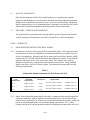
shall contain all decontamination fluids for collection and placement in a tank supplied
by Shaw . Decontamination pads made of plastic and earth, or other temporary
structures, shall not be used. Shaw will designate an area, equipped with power and
potable water, for the decontamination station(s).
All downhole drilling and development equipment will be: 1) cleaned of caked drill
cuttings, soil or other material using a brush; 2) steam cleaned using a hot water, high
pressure washer; and 3) rinsed with potable water prior to its use downhole, and between
boreholes. The subcontractor will supply steam cleaners and brushes.
Between drilling sites, the drilling rig will be decontaminated following the procedure
outlined above. Between boreholes at the same site, the back-end of the drilling rig will
be scrubbed and washed with potable water until surfaces are visibly free of soil buildup.
After cleaning and decontamination, all tool and drilling equipment which may be used
downhole must be kept clean and free of contaminants. Decontaminated equipment shall
be kept off the ground by storing on clean metal racks (not wooden pallets) and wrapped
in plastic.
All well materials, exclusive of sand pack, bentonite, and grout, shall be decontaminated
before placement into the borehole as described above. Following decontamination, all
materials shall be placed on clean metal racks or clean plastic sheeting. If materials are
not used immediately, they shall be wrapped or covered with clean plastic sheeting.
3.1.3
Well Construction
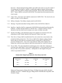
Wells will be constructed inside the drive casing which shall be driven to depth, or a
stable direct circulation mud rotary drilled boring. The screen and well casing, fitted
with sediment trap and end cap, will be suspended in the center of the borehole so that
the screen interval occurs at a depth acceptable to the field representative. The depth of
all materials placed in the well will be measured as directed by the field representative.
The sand pack material for the extraction wells will be placed through the drive casing to
an elevation approximately 3 feet above the top of the well screen. If used, the drive
casing will slowly be removed from the borehole as the sand pack is placed around the
screen. The drive casing will never be pulled higher than 2 feet below the top of the sand
pack during installation. During placement of the sand pack, frequent measurement of
the top of the sand pack shall be made to assure that the bottom of the drive casing is
never above the top of the sand pack. For direct circulation rotary drilled borings, the
sand shall be placed using a tremie pipe from the bottom of the borehole, displacing the
drilling fluid as it is placed. Prior to placing the bentonite seal, the filter pack will be
carefully surged and then remeasured to assure correct sand pack placement. If
necessary, additional sand pack material will be added to assure correct sand pack
position. A transitional filter pack, consisting of a smaller grain size, will be placed
above the primary filter pack to prevent bentonite seal intrusion into the sand pack.
A 3- to 5-foot thick bentonite seal will be placed above the top of the sand pack.
02670-5