1
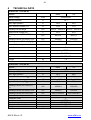
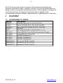
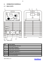
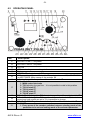
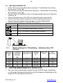
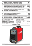
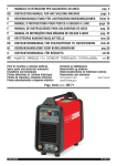
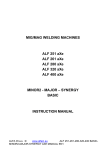
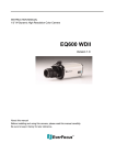
-1-
WELDING INVERTER
PEGAS 160 T PULSE HF
PEGAS 200 T PULSE HF
OPERATING MANUAL
ALFA IN a.s. ©
www.alfain.eu
NA125-4
-2CONTENT:
1
INTRODUCTION .......................................................................................3
2
3
4
5
SAFETY INSTRUCTIONS AND WARNINGS
.....................................3
ELECTROMAGNETIC COMPATIBILITY (EMC)........................................5
TECHNICAL DATA....................................................................................6
EQUIPMENT .............................................................................................7
5.1
ACCESSORIES TO ORDER ..............................................................7
6 OPERATOR CONTROLS..........................................................................8
6.1
MAIN PARTS......................................................................................8
6.2
OPERATING PANEL ..........................................................................9
6.3
PRINCIPLE OF SETTING PARAMETERS .......................................10
6.4
EN EXAMPLE OF SETTING.............................................................10
6.5
SELECTING PULSE MODE .............................................................11
7 GETTING STARTED ...............................................................................11
7.1
GETTING STARTED MMA – COATED ELECTRODE......................11
7.2
GETTING STARTED TIG .................................................................12
7.2.1 Basic settings for TIG welding – stainless steel, DC current ........12
8 ROUTINE MAINTENANCE & INSPECTION............................................12
9 STATEMENT OF WARRANTY................................................................13
10 DISPOSAL...............................................................................................14
ALFA IN a.s. ©
www.alfain.eu
-3-
1
INTRODUCTION
Congratulations on your new ALFA IN product. We are proud to have you as
our customer and will strive to provide you with the best service and reliability
in the industry.
This Operating Manual has been designed to instruct you on the correct use
and operation of your ALFA IN product. Your satisfaction with this product and
its safe operation is our ultimate concern. Therefore please take the time to
read the entire manual, especially the Safety Precautions. They will help you to
avoid potential hazards that may exist when working with this product.
Read and understand this entire Manual and your employer’s safety practices
before installing, operating, or servicing the equipment. While the information
contained in this Manual represents the Manufacturer's best judgement, the
Manufacturer assumes no liability for its use.
PEGAS 160-200 T PULSE HF weld by those methods
a) E – (MMA) coated electrodes up to 4,0 mm
b) TIG HF (High Frequency ignition)
c) TIG lift arc.
2
•
•
•
•
•
•
•
•
•
•
•
SAFETY INSTRUCTIONS AND WARNINGS
Once the packing has been opened, make sure that the machine is not
damaged. If in any doubt, call the service centre.
This equipment must only be used by qualified personnel.
During installation, any electric work must only be carried out by trained
personnel.
The machine must be used in a dry place with good ventilation.
Make sure that no metal dust can be drawn in by the fan inside the
machine, as this could cause damage to the electronic circuits.
It is prohibited to connect more than one INVERTER generator in series or
in parallel.
When installing the machine, follow the local regulations on safety.
The position of the machine must allow easy access by the operator to the
controls and connectors.
When the welding machine is operating, all its covers and doors must be
closed and well fixed.
Do not expose the welding machine to direct sunlight or to heavy rain. This
equipment conforms to protection rating IP23S.
During welding, the welding cables must be located near or at ground level.
They should be as short as possible.
ALFA IN a.s. ©
www.alfain.eu
-4•
•
•
•
•
•
•
•
•
•
•
•
•
•
•
•
The operator must wear gloves, clothes, shoes, and a helmet or a welder’s
helmet, which protect and are fire-resistant in order to protect him against
electric shock, flashes and sparks from welding.
The operator must protect his eyes with safety visor or mask designed for
welding, fitted with standard safety filters. He should also be aware that
during electrical welding ULTRAVIOLET RADIATION is emitted. Therefore
it is vital that his face is also protected from radiation. Ultraviolet rays
produce the same harmful effect as sun burning on unprotected skin.
The operator is obliged to warn anyone near the welding area of the risks
that welding involves and to arrange to provide adequate protection
equipment.
It is very important to arrange for sufficient ventilation, especially when
welding in enclosed spaces. We suggest using suitable fume extractors to
prevent the risk of intoxication by fumes or gas generated by the welding
process.
The operator must ensure all flammable materials are removed from the
work area to avoid any risk of fire.
The operator must NEVER weld containers that have previously contained
petrol, lubricants, gas or similar flammable materials, even if the container
has been empty for a considerable time. THERE IS A VERY HIGH RISK
OF EXPLOSION.
The operator must be aware of all the special regulations which he needs
to conform to when welding in enclosed spaces with a high risk of
explosion.
To prevent electric shock, we strongly suggest the following rules:
Do not work in a damp or humid environment.
Do not use the welding machine if its cables are damaged in any way.
Make sure that the earthing system of the electric equipment is correctly
connected and operational.
The operator must be insulated from the metal components connected to
the return wire.
The earthing of the piece being worked could increase the risk of injury to
the operator.
EN 60974-1 Standard: Open-circuit voltage. During the operation of the
machine, the highest voltage, with which it is possible to come into contact,
is the open-circuit voltage between the welding clamps. In our generator
this voltage is 61V respective 65 V.
The maximum open-circuit voltage of the welding machines is established
by national and international standards (EN 60974-1) depending on the
type of weld current to be used, on its waveform and on the hazards arising
from the work place. These values are not applicable to the strike currents
and those for stabilisation of the arc that could be above it.
The open-circuit voltage, for as many adjustments as possible, must never
ALFA IN a.s. ©
www.alfain.eu
-5exceed the values relating to the various cases shown in the following
table:
Case Working conditions
Open-circuit voltage
1
Places with increased risk of DC current: 113V AC current: 68V
electric shock
peak value
peak value and
48V effective
2
Places without increased risk DC current: 113V AC current: 113V
of electric shock
peak value
peak value and
80V effective
3
Torches held mechanically DC current: 141V AC current: 141V
with increased protection for peak value
peak value and
the operator
100V effective
•
In case 1, the dc welding machines with rectifier must be built in such a
way that, in case of a fault developing in the rectifier (for example open
circuit, short circuit or lack of power), the permitted values cannot be
exceeded. The welding machines of this type can be marked with the
S
•
•
3
symbol:
Before opening the machine switch off the machine and disconnect it from
the power socket.
Only personnel authorised by this company can carry out maintenance on
the machine.
ELECTROMAGNETIC COMPATIBILITY (EMC)
This welding machine conforms to EN 60974-10 standard. However, the
electromagnetic emissions generated could prove not be compatible with the
maximum permitted levels for some classes of electrical equipment, such as
the following:
• Domestic electronic appliances (radios, TVs, videos, telephones,
burglar alarms, etc.).
• Computers, robots, electro-medical instruments and life-support
systems.
• Radio-television transmitters and receivers.
• Pacemakers and hearing aids.
• All very sensitive electrical equipment.
The operator is responsible for the installation and use of the welding machine.
If there should be any fault in operations of other systems located in the
immediate vicinity of the generator, we recommend suspending operations and
consulting the manufacturers.
ALFA IN a.s. ©
www.alfain.eu
-6-
4
TECHNICAL DATA
PEGAS 160 T PULSE HF
Method
Mains voltage
MMA
TIG
V/Hz
1x230/50-60
Mains protection
A
16 T
Max. input power I1
A
32,0
23,0
Max. effective current I1eff
A
16,0
11,5
A/V
5/20,2 - 160/26,4
5/10,2 - 160/16,4
V
61,0
61,0
Welding current range
Open-circuit voltage U20
Welding current (DC=100%) I2
/U2
Welding current (DC=60%) I2/U2
A/V
80/23,2
80/13,2
A/V
100/24,0
100/14,0
Welding current (DC=x%) I2/U2
A/V
25%=160/26,4
25%=160/16,4
Power factor cos φ
0,8
Insulation class
F
Protection
IP23S
Standards
EN 60974-1
Dimensions (w x l x h)
Weight
mm
140x370x230
kg
7,5
PEGAS 200 T PULSE HF
Method
Mains voltage
Mains protection
Max. input power I1
V/Hz
A
A
34,5
29,5
Max. effective current I1eff
Welding current range
Open-circuit voltage U20
A
A/V
V
18,9
5/20,2 - 170/26,8
65,0
14,8
5/10,2 - 200/18,0
65,0
Welding current (DC=100%) I2
/U2
A/V
100/24,0
100/14,0
Welding current (DC=60%) I2/U2
A/V
130/25,2
130/15,2
Welding current (DC=x%) I2/U2
Power factor cos φ
Insulation class
Protection
Standards
Dimensions (w x l x h)
Weight
A/V
30%=170/26,8
25%=200/18,0
ALFA IN a.s. ©
MMA
mm
kg
TIG
1x230/50-60
16 T
0,8
F
IP23S
EN 60974-1
140x370x230
8,2
www.alfain.eu
-7-
ALFA IN continuously strives to produce the best product possible and
therefore reserves the right to change, improve or revise the specifications or
design of this or any product without prior notice. Such updates or changes do
not entitle the buyer of equipment previously sold or shipped to the
corresponding changes, updates, improvements or replacement of such items.
5
EQUIPMENT
5.1
ACCESSORIES TO ORDER
Item No.
VM0253
5.0160
VM0184-1
5.0110
4341
7S2.A001
7S2.A002
712.A011
712.A012
712.A013
400P216175
400P224175
400P232175
ALFA IN a.s. ©
Description
Welding Cable Set 2x 3m 35-50 160A
Box for PEGAS 500 x 180 x 585 mm RED
Hose Gas ATA PULSE 3m G1/4, D 9.5 HD
Box blue
Valve Red.AR MIDI-C M14G W21,8 x 1,14
Torch ABITIG 17 4m 35-50 with connector Pegas
Torch ABITIG 17 8m 35-50
Set SR17/18/26d=1,6
Set SR17/18/26d=2,4
Set SR17/18/26d=3,2
Electrode T 2%Th 1.6x175
ElectrodeT 2%Th 2.4x175
Electrode T 2%Th 3.2x175
www.alfain.eu
-8-
6
OPERATOR CONTROLS
6.1
MAIN PARTS
Fig . 1 Main parts
Pos.
Description
1
Operating panel LED ON
2
3
4
5
6
7
8
Gas outlet connector
Panel quick connector Torch control connector
Panel quick connector +
ON/OFF switch
Mains socket with a plug
Gas inlet connector
ALFA IN a.s. ©
www.alfain.eu
-96.2
OPERATING PANEL
Pos.
Description
9
LED HOT START – only MMA
10
LED ARC FORCE - only MMA
11
12
13
14
LED ON
LED over heating or over voltage in the mains
Display
LED PULSE selected – only TIG
MMA – position of the method switch 17, can be set current 25, HOT START 9
or ARC FORCE 10 by means of the encoder 21
Adjusting the gas flow - position of the method switch 17
Method switch
1. MMA coated electrode
2. TIG Adjusting the gas flow - it is not possible to weld in this position
3. TIG LA start 4T
4. TIG LA start 2T
5. TIG HF start 4T
6. TIG HF start 2T
TIG LA 4T – Lift Arc ignition TIG, four stroke - position of the method switch 17
TIG LA 2T – Lift Arc ignition TIG - position of the method switch 17, the start
current and end current are set to 5 A, impossible to change.
TIG HF 4T –TIG HF ignition, four stroke - position of the method switch 17
ENCODER
1. Every press of the encoder switches between selecting mode of the
parameter to be set and setting mode of the selected parameter
15
16
17
18
19
20
21
ALFA IN a.s. ©
www.alfain.eu
-10-
22
23
24
25
26
27
28
29
30
31
32
2. By means of turning selects the parameters to be set respective
sets the selected parameters.
3. Sets the current 25 – that function is active strait after switching the
machine ON or if no pressing of the encoder was done.
LED pre gas time - only TIG
LED start current - only TIG
LED up slope time - only TIG
LED welding current – all methods
LED lower current – only TIG, just in case the pulse LED 14 illuminates
LED pulse frequency - only TIG, just in case the pulse LED 14 illuminates
LED pulse width - only TIG, just in case the pulse LED 14 illuminates
LED down slope time - only TIG
LED end current - only TIG
LED post gas time - only TIG
TIG HF 2T –TIG HF ignition, two stroke - position of the method switch 17
6.3 PRINCIPLE OF SETTING PARAMETERS
• The machine will be the Main Mode after switching ON - LED 25 will
illuminate and turning the encoder 21 will change main welding current
•
•
•
•
•
6.4
.
Turning the encoder 21 changes parameters.
Pressing the encoder 21 activates function of selecting a new parameter to
be set. That function will stay active just for 3 s. In case there is no
movement of the encoder during the period of those 3 s the function
deactivates and the machine switches automatically into the Main Mode.
After selection of a LED of a parameter to be set, appropriate LED will start
flashing. That function will stay active just for 3 s. It is possible to change
the value of the appropriate parameter by means of encoder 21 during that
time.
To save the setting press the encoder 21 or wait for more than 3 s
The machine will switch back to the Main Mode after any change of setting
3 s later of last movement of the encoder 21.
EN EXAMPLE OF SETTING
•
Select method
•
.
illuminate
Press the encoder 21, then by means of turning the encoder select
LED 24
ALFA IN a.s. ©
by means of method switch 17, LED 25 will
.
www.alfain.eu
-11•
•
Press again the encoder 21, LED 24 will start flashing. Now you can
change the up slope time by means of turning the encoder 21.
Press the encoder 21 third time. That will save the change of the
parameter. In case you omit to press the encoder for the third time the
machine will save the parameter change automatically after 3 s of no
movement of the encoder 21. LED 25 will illuminate then.
6.5 SELECTING PULSE MODE
• Select the required TIG method by means of method switch 17, LED 25 will
•
•
•
7
.
illuminate
Press the encoder 21, then by means of turning the encoder select
LED 14
.
Press again the encoder 21, LED 14 will flash. Press the encoder 21 for the
third time. On the display will appear “ON”. The function will be
automatically saved and LED 25 – main welding current will become active.
One can set off the pulse similarly. Just select “OFF“
GETTING STARTED
Insert the mains plug into a suitable 1x230 V mains socket. The supply fuses
or circuit breaker should correspond to the technical data in section 3. Switch
the machine on by the ON/OFF switch 6.
7.1 GETTING STARTED MMA – COATED ELECTRODE
• Set the method switch 17 to position 15 MMA.
• Connect the welding cables to the panel quick connectors 3 and 5 (+ - )
according the instruction on the electrodes packing.
• Set the welding current by means of encoder 21. The values will be
showed on the display 13.
• You may adjust HOT START and ARC FORCE similarly to 6.4 EN
EXAMPLE OF SETTING .
Prevent touching the electrode any metal material for
•
NOTE
•
in this mode the terminals (5) and (6) are under current.
Insert the coated electrode into the electrode holder and you may start
welding.
ALFA IN a.s. ©
www.alfain.eu
-127.2 GETTING STARTED TIG
• Fit the TIG Torch to the Panel quick connector - 3 and fasten it by turning
the connector to the right.
• Connect the work lead to Panel quick connector + 5 and fasten it by turning
the connector to the right.
• Connect the to the reduction valve on the gas cylinder and on the Gas inlet
connector 8.
• Connect the gas hose of the TIG torch onto Gas outlet connector 2.
• Connect the torch control connector onto the matching connector 4.
• Connect the work clamp to the work piece or at the welding table.
• Set the method switch 17 to desired TIG method.
Symbol
Description
4T LA – four stroke, contact ignition – Lift Arc
2T LA – two stroke, contact ignition – Lift Arc
4T HF – four stroke, HF ignition (High Frequency)
2T HF – two stroke, HF ignition (High Frequency)
7.2.1
Material
thickness
mm
1
1,5
2
3
4-5
8
•
Basic settings for TIG welding – stainless steel, DC
current
Tungsten
electrode
diameter
mm
1
1,5
2
2-3
3-4
Filler material
diameter mm
Welding
current
A
1,5
1,5
2
2-3
3-4
40-60
50-90
80-100
90-140
110-180
Argon flow
Gas
l/min
nozzle mm
3
4
4
5
5
10
10
12
12
12
ROUTINE MAINTENANCE & INSPECTION
The only routine maintenance required for the PEGAS range of machines
is a thorough cleaning and inspection, with the frequency depending on the
usage and the operating environment.
ALFA IN a.s. ©
www.alfain.eu
-13-
WARNING •
•
Disconnect the PEGAS from the mains supply voltage before
disassembling.
Special maintenance is not necessary for the control unit parts in the
Welder. If these parts are damaged for any reason, replacement is
recommended.
CAUTION •
•
•
•
•
9
•
•
•
•
•
Do not blow air into the welder during cleaning. Blowing air into the welder
can cause metal particles to interfere with sensitive electronic components
and cause damage to the welder.
To clean the welder, disconnect it from the mains supply voltage then open
the enclosure and use a vacuum cleaner to remove any accumulated dirt
and dust. The welder should also be wiped clean. If necessary, solvents
that are recommended for cleaning electrical apparatus may be used.
Troubleshooting and repairing of PEGAS welding equipment should only
be carried out only by suitably qualified or competent person.
A ‘competent person’ must be a person who has acquired through training,
qualification or experience, or a combination of them, the knowledge and
skills enabling that person to safely carry out a risk assessment and repairs
to the electrical equipment in question.
The person carrying out the servicing needs and repairs must know what to
look at, what to look for and what to do.
STATEMENT OF WARRANTY
In accordance with the warranty periods stated below, ALFA IN guarantees
the proposed product to be free from defects in material or workmanship
when operated in accordance with the written instructions as defined in this
operating manual.
ALFA IN welding products are manufactured for use by commercial and
industrial users and trained personnel with experience in the use and
maintenance of electrical welding and cutting equipment.
ALFA IN will repair or replace, at its discretion, any warranted parts or
components that fail due to defects in material or workmanship within the
warranty period. The warranty period begins on the date of sale to the end
user.
If warranty is being sought, please contact your ALFA IN product supplier
for the warranty repair procedure.
ALFA IN warranty will not apply to:
• Equipment that has been modified by any other party other than ALFA
IN’s own service personnel or with prior written consent obtained from
ALFA IN Service Department.
ALFA IN a.s. ©
www.alfain.eu
-14•
•
Equipment that has been used beyond the specifications established in
the operating manual.
• Installation not in accordance with the installation/operating manual.
• Any product that has been subjected to abuse, misuse, negligence or
accident.
• Failure to clean and maintain (including lack of lubrication,
maintenance and protection), the machine as set forth in the operating,
installation or service manual.
Within this operating manual are details regarding the maintenance
necessary to ensure trouble free operation.
NOTE •
10
Warranty repairs must be performed by either an ALFA IN Service Centre,
an ALFA IN distributor or an Authorised Service Agent approved by the
company ALFA IN.
DISPOSAL
Only for EU countries. Do not dispose of electric tools together with
household waste material.
In accordance with European Council Directive 2002/96/EC on
electrical and electronic equipment waste and its implementation in
accordance with national law, electric tools that have reached the end of their
service life must be collected separately and returned to an environmentally
compatible recycling facility.
ALFA IN a.s. ©
www.alfain.eu