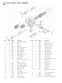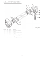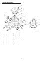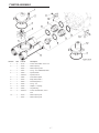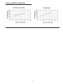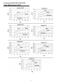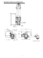
1
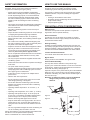
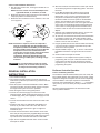
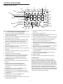
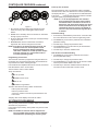
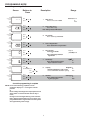
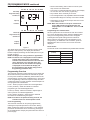
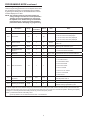
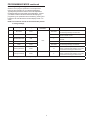
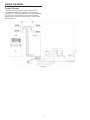
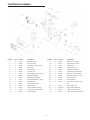
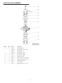
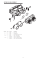
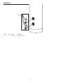
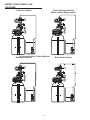
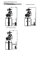
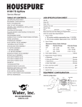
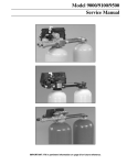
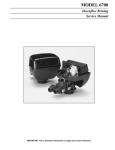
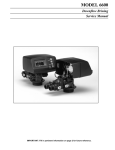
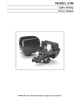
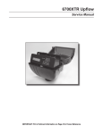
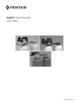
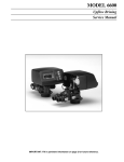
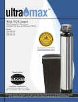
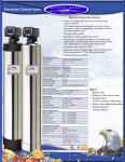
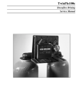
IOM-WQ-PROSENSE
Instructions for Installing ProSense
Twin Alternating Water Softening Systems
Service Manual
TABLE OF CONTENTS
JOB SPECIFICATION SHEET
JOB SPECIFICATION SHEET................................................1
EQUIPMENT CONFIGURATION............................................1
SAFETY INFORMATION.........................................................2
HOW TO USE THIS MANUAL................................................2
GENERAL AND COMMERCIAL INSTALLATION
INSTRUCTIONS......................................................................2
CONTROLLER FEATURES....................................................4
PLACING WATER CONDITIONING SYSTEM INTO
OPERATION............................................................................5
PROGRAMMING MODE.........................................................6
DISINFECTION OF WATER CONDITIONING SYSTEMS......11
WIRING DIAGRAMS...............................................................12
POWERHEAD ASSEMBLY.....................................................13
ProSense CONTROL VALVE ASSEMBLY..............................14
ProSense SECOND TANK ASSEMBLY..................................15
3/4" METER ASSEMBLY.........................................................16
1" METER ASSEMBLY............................................................17
ProSense BYPASS VALVE ASSEMBLY..................................18
BYPASS VALVE ASSEMBLY..................................................19
PROBE KIT.............................................................................20
TROUBLESHOOTING............................................................21
ProSense METER FLOW DATA..............................................23
ProSense INJECTOR FLOW DATA
(1600 SERIES INJECTORS)...................................................24
ProSense CONTROL DIMENSIONS......................................25
WATER CONDITIONER FLOW DIAGRAMS..........................26
SERVICE ASSEMBLIES.........................................................28
Job No:____________________________________________
Model No:__________________________________________
Water Test:__________________________________________
Capacity Per Unit:____________________________________
Mineral Tank
Size:_____________ Diameter:___________ Height:__________
Brine Tank Size and Salt Setting per Regeneration:__________
ProSense Control Valve Specifications:
1. Timer Gallon Setting:________________________ Gallons
2. Regeneration Program Setting:
a. Brine and Slow Rinse:______________________Minutes
b. Backwash:_______________________________Minutes
c. Rapid Rinse:______________________________Minutes
d. Brine Tank Refill:__________________________Minutes
3. Drain Line Flow Control:________________________ gpm
4. Brine Refill Rate:______________________________ gpm
5. Injector Size:_____________________________________
EQUIPMENT CONFIGURATION
ProSense Water Softener Configuration
Figure 1
SAFETY INFORMATION
HOW TO USE THIS MANUAL
This water conditioner’s control valve conforms to UL/CE
Standards. Generic valves were tested and certified for
compliance as verified by the agency listing.
• Please review the entire Installation and Operation
Manual before installing the water conditioning system.
• As with all plumbing projects, it is recommended that
a trained professional water treatment dealer install
the water conditioning system. Please follow all local
plumbing codes for installing this water conditioning
system.
• This system will not make microbiologically unsafe water
safe. Water that is unsafe must be treated separately
from this conditioner.
• This water conditioning system is to be used only for
potable water.
• Inspect the water conditioning system for carrier shortage
or shipping damage before beginning installation.
• Use only lead-free solder and flux, as required by
federal and state codes, when installing soldered copper
plumbing.
• Use caution when installing soldered metal piping near
the water conditioning system. Heat can adversely affect
the plastic control valve and bypass valve.
• All plastic connections should be hand tightened. Teflon®
tape may be used on connections that do not use an
O-ring seal. Do not use pipe dope type sealants on the
valve body. Do not use pliers or pipe wrenches.
• Do not use petroleum-based lubricants such as Vaseline,
oils or hydrocarbon-based lubricants. Use only 100%
silicone lubricants.
• Use only the power transformer supplied with this water
conditioning system.
• All electrical connections must be completed according to
local codes.
• The power outlet must be grounded.
• Install an appropriate grounding strap across the inlet and
outlet piping of the water conditioning system to ensure
that a proper ground is maintained.
• To disconnect power, unplug the AC adapter from its
power source.
• Observe drain line requirements.
• Do not support the weight of the system on the control
valve fittings, plumbing, or the bypass.
• Do not allow this water conditioning system to freeze.
Damage from freezing will void this water conditioning
system’s warranty.
• Operating ambient temperature: 34° to 120°F (1° to
49°C).
• Operating water temperature: 34° to 100°F (1° to 38°C).
• Operating water pressure range : 25 to 120 psi (1.38
to 8.27 bar). In Canada the acceptable operating water
pressure range is 25 to 100 psi (1.38 to 6.89 bar).
• Observe all warnings that appear in this manual.
• Keep the media tank in the upright position. Do not turn
upside down or drop. Turning the tank upside down or
laying the tank on its side can cause media to enter the
valve.
• Use only regenerants designed for water conditioning. Do
not use ice melting salt, block salt or rock salt.
During cold weather it is recommended that the installer warm
the valve to room temperature before operating.
Teflon® is a trademark of E.I. duPont de Nemours.
This installation manual is designed to guide the installer
through the process of installing and starting up water
conditioning systems featuring the ProSense controller.
This manual is a reference and will not include every system
installation situation. The person installing this equipment
should have:
• Training on the ProSense control valve.
• Knowledge of water conditioning and how to determine
proper control settings.
• Adequate plumbing skills.
PRE-INSTALLATION CONSIDERATIONS
Water Pressure
A minimum of 25 pounds of water pressure is required for
regeneration valve to operate effectively.
Electrical Facilities
A continuous 115 volt, 60 Hertz current supply is required.
Make certain the current supply is always hot and cannot be
turned off with another switch.
Existing Plumbing
Condition of existing plumbing should be free from lime and
iron buildup. Piping that is built up heavily with lime and/or iron
should be replaced. If piping is clogged with iron, a separate
iron filter unit should be installed ahead of the water softener.
Location Of Softener And Drain
The softener should be located close to a drain.
Bypass Valves
Always provide for the installation of a bypass valve.
Tank and Probe Assembly
Use only 100% silicone lubricant on the probe O-rings
(Figure 2). Do not allow the lubricant to come into contact with
the probe pins. Install the probe assemblies into the tank and
secure with the locking clasp (Figure 3).
Important: The pins on the probes will only fit into the bulkhead
fittings one way. The pins must go into the matching holes at
the bottom of the fitting. The probe with the shortest length of
wire must be on top.
NOTE: Do not attempt to tighten or loosen the Bulkhead
fittings as they are secured with a locking
adhesive.
Probe Pins
Lubricate
Figure 2
Figure 3
Locking Clasp
2
Bulkhead Fitting
Valve to Tank Installation Instructions
1. Spin the valve onto the tank, ensuring the threads are not
cross-threaded.
NOTE: The main control valve and tank adaptor have
right-hand threads, or clockwise, to install.
2. Rotate the valve freely without using force until it comes to
a stop (this position is considered zero).
3. Rotate the valve clockwise from zero, between ¼ turn and
½ turn (Figure 4).
10. Allow the inside hot and cold faucet to remain open until all
air has been purged from the plumbing system. Then close
the faucet
11. L
ocate Manual Regeneration Options in this manual
and follow the steps to initiate an Immediate Manual
Regeneration. Once you have read that section place
the system in backwash and unplug the system from
its electrical outlet once it has cycled into the backwash
position. This will stall the unit is backwash so can be
purged from one of the tanks. Look on the right side of the
control valve, it has indicators showing which position the
control valve is in during Regeneration and which tank is
In Service. Tank one has control valve and tank two has
adapter.
12. Adjust the user supplied feed water valve to 1/4 open and
place the bypass valve into the service position.
13. Air will come out of the drain line until the tank in backwash
is completely purged of air. Then water will flow to drain.
Allow water to flow to drain for 15 minutes or until the water
to drain is clear of resin color throw.
14. P
lug the system back into the electrical outlet and manually
cycle it through the remaining regeneration steps until it
arrives in the service position.
15. R
epeat installation steps 11, 12, 13, and 14 of the General
Installation Instructions to purge the air from the second
tank.
16. Check for leaks and repair as needed.
17. Installation is now complete and the system is ready for
programming and one cycle of brine tank refill so that the
correct amount of water is in the brine tank for the first
regeneration cycle. The brine tank refill must be done after
programming the system.
Figure 4
NOTE: If lubricant is required, a silicone compound is
strongly recommended. Dow Corning® Silicone
Compound (available from Watts), is recommended
for best possible results. Dow Corning® 7 Release
Compound is used in the manufacture of this
control valve. The use of other types of lubricants
may attack the control’s plastic or rubber
components. Petroleum-based lubricants can
cause swelling in rubber parts, including O-rings
and seals.
WARNING: Do not exceed water pressure of 125 psi
(8.6 bar). Do not exceed 110°F (43.3°C). Do
not subject unit to freezing conditions.
ProSense Controller Operation
GENERAL INSTALLATION
INSTRUCTIONS
Power Loss Memory Retention
The ProSense controller features battery-free Time of Day and
Day of Week retention during temporary loss of power. A super
capacitor is designed to keep time for 8 to 24 hours depending
on the installation. If the super capacitor is exhausted the
ProSense control will display four dashes (- - : - - ) immediately
upon power up. The Time of Day and Day of Week must be
reset.
All other programmed parameters are stored in the static
memory and are retained.
1. Turn off water heater(s).
2. Turn off the main water supply to the home and open an
inside faucet (cold and hot) to relieve any pressure within the
plumbing system.
3. Place the system in the desired installation location. Make
sure that the location is level and sturdy enough to support
the weight of the system once it is in operation.
4. Place the bypass valve in the bypass position.
5. Connect the cold water supply to the inlet of the water
softening system. While constructing the supply line, install
a master supply valve (user supplied) in the supply line and
close it.
6. Connect the feed water line to the home to the outlet of the
system.
7. Plumb the drain line to an appropriate drain abiding buy
all local, city, and state codes. Use a 3/4" drain line for
backwash flow rates that exceed 7 gpm or length that
exceeds 20' (6 m).
8. Connect the brine tank to the water softener control valve
brine inlet port using the factory supplied fittings and tubing.
Add enough water to the brine tank so that water covers the
top of the air check. DO NOT ADD SALT AT THIS TIME.
9. Open the user supplied feed water valve. Check for leaks
and repair as needed.
3
CONTROLLER FEATURES
Display Icons & Cursors
9
16
10
SU MO TU
14
2
7
8
WE TH FR SA DAYS
1
Time/Day
13
Regeneration Time
15
12
Salt Amount
11
x2
Capacity
Hardness
26
25
24
C
P
H
23
3
PM
MIN
g/L
KG
x100
Lbs/ft
20
21
22
3
4
5
6
17
18
19
16.These cursors appear next to the item that is currently
displayed.
17.X100 multiplier for large values.
18.When Lbs/ft3 is displayed the value for regenerant amount
entered is in pounds/cubic foot of resin.
19.Faucet is displayed when the current flow rate is displayed.
Control may show the faucet and "0", indicating no flow.
20.Maintenance interval display turns on if the months in
service exceed the value programmed in P11.
21.Displays the tank in service durning normal operating
mode. Used with #22, #23 and #24 in programming mode
or regeneration.
22.History Values (H). The number displayed by #23 identifies
which history value is currently displayed.
23.Parameter (P). Displayed only in Level II Programming.
The number displayed by #21 identifies which parameter is
currently displayed.
24.Cycle (C). The number displayed by #21 is the current
cycle in the regeneration sequence.
25.Hardness setting.
26.Capacity display—shows estimated system capacity
NOTE: In normal operation and during programming, only
a few of the icons are actually displayed.
1. This cursor is displayed when the days between
regeneration are being programmed (used with .5 to 30 day
regeneration programming).
2. One of these cursors is displayed to indicate which day will
be programmed into the controller.
3. "PM" indicates that the time displayed is between 12:00
noon and 12:00 midnight (there is no AM indicator). PM
indicator is not used if clock mode is set to 24-hour.
4. When "MIN" is displayed, the value entered is in minute
increments.
5. When g/L is displayed, the value for regenerant amount
entered is in grams/Liter of resin.
6. When "Kg" is displayed, the value entered is in kilograms or
kilograins.
7. Four digits used to display the time or program value. Also
used for error codes.
8. Colon used as part of the time display.
9. Locked/unlocked indicator. In Level I Programming this
is displayed when the current parameter is locked-out.
It is also used in Level II Programming to indicate if
the displayed parameter is locked (icon flashes) when
controller is in Level I.
10.When "x2" is displayed, a second regeneration has been
called for.
11.The recycle sign is displayed (flashing) when a
regeneration at the next time of regeneration has
been called for. Also displayed (continuous) when in
regeneration.
12.The display cursor is next to "SALT AMOUNT" when
programming the amount of regenerant.
13.The display cursor is next to "REGENERATION TIME"
when programming the time of regeneration and the days
of regeneration.
14.The display cursor is next to "TIME/DAY" when
programming the current time and day.
15.The hourglass is displayed when the motor is running. The
camshaft should be turning.
Check Salt Light
A check salt LED light indicator is located at the bottom
left of the controller keypad buttons. This light indicates, by
illuminating, that the conductivity probes did not see a shift in
conductivity during the last service cycle before regeneration
was called for by the meter. This could be an indicator that the
brine tank is out of salt. It could also indicate that the hardness
of the feed water has come down and the hardness value
programmed in Level 1 Programming needs to be adjusted to
a more accurate value. Upon start up of a new system this light
will stay illuminated until the resin has exhausted a few times.
Then it will turn off and function normally.
4
CONTROLLER FEATURES continued
Keypad - Buttons
1
2
Power-up The Controller
3
Plug the transformer into a non-switched outlet. The display
will show 9100. If this is the first time the control is powered up
the display will show "_.__" if the product is for USA otherwise
it will show "___". Finish programming the ProSense controller
using the Level I Programming instructions.
NOTE: Err3 will be displayed when the controller
does not detect the cam at the home position
and that the motor is turned on. As soon as it
detects the cam at the home position, the motor
will be turned off and error will disappear. The
camshaft will move to service if not already in
service. These cam movements may take up to
5 minutes.
4
Figure 5
1. SET. Used to accept a setting that normally becomes
stored in memory. Also used together with the arrow
buttons.
2. DOWN arrow. Generally used to scroll down or decrement
through a group of choices.
3. UP arrow. Generally used to scroll up or increment through
a group of choices.
4. REGENERATE. Used to command the controller to
regenerate. Also used to change the lock mode.
NOTE: If a button is not pushed for thirty seconds, the
controller returns to normal operation mode.
Pushing the Regenerate button immediately
returns the controller to normal operation except
when the controller is in regeneration mode or
Level II Programming mode.
Flowmeter Setting
1. P
ress UP key and DOWN key and hold for 3 seconds. Now
the control will enter into the Level II Programming mode.
2. U
se DOWN key to scroll to the parameter P16: Flowmeter
parameter setting.
3. U
se SET key to change the parameter value.
4. U
se UP/DOWN key to set the value as per the flowmeter
connected to the system.
5. U
se SET key to store the modified value.
Tank In Service Parameter Setting
1. U
se DOWN key to scroll to the parameter P18: Tank In
Service parameter setting.
2. U
se SET key to change the parameter value.
3. U
se UP/DOWN key to set the value as per the tank number
shown by the indicator lablel on the valve.
4. U
se SET key to store the modified value and wait for 30
seconds to let the control back to service mode.
Programming Conventions
The ProSense controller is programmed using the buttons on
the keypad. The programming instructions are described two
ways whenever a section has keypad input.
First a table shows simplified instructions. Second, text follows
that describes the action. In each table:
"Action" lists the event or action desired.
"Keys" are listed as:
UP for up arrow
DOWN for down arrow
SET for set
REGEN for regeneration
"Duration" describes how long a button is held down:
P/R for press and release
HOLD for press and hold
X sec for a number of seconds to press the button and
hold it down
"Display" calls out the display icons that are visible.
SYSTEM PROGRAMMING
After you have performed the installation steps, the conditioner
will need to be programmed.
Follow these steps carefully, as they differ from previous valve
instructions.
NOTE: The ProSense controller will be shipped in the
service (treated water) position. Do not rotate the
camshaft before performing the following steps.
5
PROGRAMMING MODE
Level I Programming - ProSense
Screen
SU MO TU
Buttons to
Press
Description
Range
WE TH FR SA DAYS
Time/Day
Regeneration Time
then
Salt Amount
or
press
Capacity
1.
Resin Volume
volume
Select correct resin volume
2.
Time off Day
Day (12 hr
hr.)
.)
Set to time of day
day
Cubic ffeet:
eet: 0.75
to
4.00
Hardness
SU MO TU
WE TH FR SA DAYS
Time/Day
Regeneration Time
PM
Salt Amount
press
then
or
SU MO TU
WE TH FR SA DAYS
press
Time/Day
Regeneration Time
Salt Amount
then
or
SU MO TU
press
Salt Amount
then
Capacity
or
SU MO TU
WE TH FR SA DAYS
Time/Day
press
Regeneration Time
Salt Amount
then
Capacity
SU MO TU
5.
Days Ov
Overr
Days
erride
ide
Leav
Leave at 0 to disab
disable
le
or
Set to desired days betw
between
ween
regener
ation
regeneration
7.
Salt Dosage
Set to desired desired dosage
lbs per cubic ffeet
eet of resin
8.
Kilograins: 1
Capacity
to
Capacity calculated by Logix Control
900
Use to OVERRIDE calculated capacityy
9.
Hardness
Set to actual water hardness
in grains per gallon
or
press
Salt Amount
then
Capacity
Lbs/ft
Hardness
SU MO TU
3
WE TH FR SA DAYS
Time/Day
Regeneration Time
or
press
press
to override press
Salt Amount
then
KG
Capacity
Hardness
or
press
SU MO TU
Days: 0
0.5 to 30
(Disable)
WE TH FR SA DAYS
Time/Day
Regeneration Time
Capacity
Time of Regeneration
Regeneration
regeneration
Set to desired time of regeneration
press
Hardness
Hardness
4.
press
Hardness
Salt Amount
Day of Week
Day
Set to actual day
week
eek
day of the w
WE TH FR SA DAYS
Time/Day
Regeneration Time
Regeneration Time
3.
3.
press
Capacity
Hardness
Time/Day
indicator.
Note: Setting includes PM indicator
r.
press
Capacity
Hardness
bs/f
/f t3 : 3
Lbs/f
to
18
15
WE TH FR SA DAYS
press
then
or
press
Control programming
is is
complete
Controller
programming
complete
NOTE: If one of the following conditions occur:
Controller displays Err3 and goes to home
position
or
Power outage discharges the supercapacitor and
when power is restored and the time of day is
reset;
the regen icon will begin flashing. This indicates
that a delayed regeneration will occur at the next
programmed time of regeneration and the system
will regenerate by water usage.
6
Grains/gal: 3
to
200
PROGRAMMING MODE continued
In Service Display
SU MO TU
WE TH FR SA DAYS
SU MO TU
WE TH FR SA DAYS
• Resin Volume Setting: Set to match the volume (cubic
feet) of resin in the mineral tank.
• Time of Day: Includes PM indicatior. Can be set to display
as a 24-hour clock. See Level II programming.
• Day of Week: Set to actual day of the week.
• Time of Regeneration: Fully adjustable. Default is 2:00 AM.
• Days Override: Range 0.5 to 30 days. Leave at 0 to disable.
• Salt Dosage: Set at pounds of salt per cubic foot of resin
in the conditioner tank.
NOTE: When the controller is set up for a twelve-hour
clock a PM indicator will illuminate when the
displayed time is in the PM hours. There is no AM
indicator.
Time & Day
Regen Time & Day
Salt Amount
Capacity
Hardness
Programming the Lockout Feature
All Level I parameters can be locked out when the controller
is in Level II Programming. Simply press the REGEN button
during Level II Programming and a lock icon will appear
indicating that the specific setting has been locked out.
When locked out, the setting cannot be adjusted in Level
I Programming. To disable the Lock Out feature, press the
REGEN button when in Level II. The lock icon will not be
displayed.
Time & Day
Regen Time & Day
Salt Amount
Capacity
Hardness
Resin Volume
The amount of resin can be determined by the diameter of the tank.
Figure 6
The display shows the number of the tank in service (small
digit next to CPH position). The display also alternates
between Capacity Remaining and Flow Rate (faucet icon) for
the tank in service.
NOTE: The Regen icon is only on when in regeneration.
NOTE: The faucet icon is displayed on all the ProSense
controls when there is flow. The ProSense
controller will show the faucet icon when the flow
rate is displayed, even if the flow rate is zero.
The faucet icon will turn off when the capacity
is displayed. In service flow rate display can
be replaced with a clock display using Level II
Programming (Parameter P10).
Programming Overview
The ProSense controller includes multiple program levels that
allow water treatment professionals to customize the system
for many water conditions. Additionally, historical data can be
viewed allowing quick and easy troubleshooting. In most cases
Level I Programming is all that is required to set up the water
conditioning system for proper operation. A brief description of
each program level is listed below.
Level I - Used to program controller for normal applications.
Level II (P-Values) - Allows the installer to customize
programming for non-standard applications.
Level III (C-Values) - Allows the installer to adjust length of
select cycles for non-standard applications.
Level IV History (H-Values) - Allows access to historical
information for troubleshooting the system.
NOTE: If a button is not pushed for thirty seconds, the
controller returns to normal operation mode.
Level I Programming
The ProSense controller can be quickly programmed by
following the sequential procedure in the section "Placing
Water Conditioning System Into Operation". Level I Program
parameters are those that can be accessed by pressing the
UP or DOWN buttons. Step-by-step instructions are shown on
previous page.
7
Tank Diameter
(inches)
Resin Volume
8
0.75
Cubic Feet
9
1
10
1.5
12
2
PROGRAMMING MODE continued
Level II Programming - P Values
Level II Programming parameters can be adjusted to fine-tune
the conditioner's operation. The parameters are accessible
by pressing and holding the UP and DOWN buttons until the
controller displays a "P" value.
NOTE: The controller must be in the home position to
change settings. See Table for Level II parameters.
Typically the Level II parameters will not need to
be adjusted as the default settings accommodate
most applications. Contact your water treatment
professional before attempting any programming.
Description
P9
Units of Measure
Range
Minimum
Increments
Default
0-1
1
(2)
Units
Notes
0 = US
1 = Metric
0 = 12 hour clock: flow rate displayed
P10
Clock Mode
0-3
1
1 = 24 hour clock: flow rate displayed
(2)
2 = 12 hour clock; Time of Day displayed
3 = 24 hour clock; Time of Day displayed
0 = Dissabled. Number of days per month is
fixed at 30.
P11
Service Interval
0-99
1
0
Months
P12*
Resin Tank Sensor
Placement
60-01
1
20
% of Capacity
P13
Disable Resin Tank
Sensors
0-1
1
0
P14
Refill Rate
1-700
1
(1)
gpm x 100
Used with salt amount to calculate refill time.
P15
Draw Rate
1-700
1
(1)
gpm x 100
Used with salt amount to calculate draw time.
Expressed as a percentage of resin bed capacity
remaining after lowest set of pins.
0 = Resin Tank Sensors Enabled
1 = Resin Tank Sensors Disabled
1 = 1" Autotrol turbine
2 = 2" Autotrol turbine
3 = User defined K-factor
4 = Fleck 3/4" Paddle
P16
Flow sensor select
1-4
1
4
5 = Fleck 3/4" Turbine
6 = Fleck 1" Paddle
7 = Fleck 1"/1-1/2" Turbine
8 = Fleck 1-1/2" Paddle
9 = Meter Factor
P17
K-factor or Pulse
equivalent
P18
Tank in Service
P19
Cleaning Cycle Interval
K-factor P16 = 3;
0.01-99.99
0.01
0.01
1-2
1
1
Select the Tank in Service.
0-100
1
6
Number of standard regeneration cycles
between cleaning regeneration cycles.
Pulse Equivalent P16 = 9
*The controller will automatically adjust the Hardness Setting P8 when the sensors in the resin tank detect a hardness front passing. This
automatic adjustment to the hardness setting may result in the system passing hard water near the end of the service cycle if the resin tank
sensor placement setting P12 is wrong. The sensor placement setting P12 must be reduced to eliminate the problem. Reducing the Capacity
Setting P7 or increasing the Hardness setting P8 will only produce a temporary solution.
NOTE: (1) Default selected with initial setting value.
(2) Facotry Default is "0" for North America units and "1" for World units.
8
PROGRAMMING MODE continued
Level III Cycle Programming - C Values
Several Level III program parameters can be adjusted to
fine-tune valve operation for non-standard applications.
Typically these parameters will not need to be adjusted as
the default settings accommodate most applications. Contact
your Water Treatment Professional before attempting any
programming. The parameters are accessible by pressing and
holding the UP and SET buttons until the display shows a “C”
value.
NOTE: The controller must be in the treated water position
to change settings.
C#
C1*
C2
C3
C4
C5*
C13
C14
Minimum
Increments
Description
Range
Default Setting
Brine Draw
0-200
See Notes
Automatically calculated from resin volume
and salt dosage settings and draw rate.
Slow Rinse
0-200
See Notes
Initial time automatically calculated to provide
two bed volumes of rinse.
Standard Backwash
0-20
7
Flow rate dictated by size of drain line flow
controller.
Standard Fast Rinse
0-200
3
Rinses residual regenerant from tank.
Refill
0-200
See Notes
Cleaning Backwash
0-200
14
Control uses C13 in place of C3 when the
number of standard regenerations is more than
or equal to the cleaning cycle interval P19.
Cleaning Fast Rinse
0-200
6
Control uses C14 in place of C4 when the
number of standard regenerations is more than
or equal to the cleaning cycle interval P19.
1 Min
*Cannot be changed in Level III Cycle Programming.
9
Notes
Automatically calculated from resin volume
and salt dosage settings and refill rate.
PROGRAMMING MODE continued
Level IV Viewing History - H Values
Historical information can be viewed by pressing the SET and
DOWN buttons simultaneously, with the ProSense controller in
the home position. Release both buttons when the controller
displays an “H” value. Press the UP or DOWN buttons to
navigate to each setting.
H#
Description
Range
Notes
Cubic Feet or Liters
Resin Volume, Holding SET for 3 seconds
will reset control to factory defaults
H0*
Initial Setting Value
H1
Days since last regeneration
H2
Current Flow Rate
Depends on turbine used
H3
Water used today in gallons or m3 since Time of
Regeneration
0-131,070 or 0-1,310.7 m3
H4
Water used since last regeneration in gallons or m3
0-131,070 or 0-1,310.7 m3
H5*
Total water used since reset in 100s
H6*
Total water used since reset in 1,000,000
H7
Average usage for Sunday in gallons or m3
H8
Average usage for Monday in gallons or m
H9
Average usage for Tuesday in gallons or m
H10
Average usage for Wednesday in gallons or m
H11
Average usage for Thursday in gallons or m
H12
Average usage for Friday in gallons or m
H13
Average usage for Saturday in gallons or m
H14
Average service cycle
H15*
Peak Flow Rate
0-255
0-999900 gallons or 0-9999m3
Holding SET key for 3 seconds will reset
H5 and H6 to zero.
4,294 x 106 gal or 4,264 x 104 m3
Holding SET key for 3 seconds will reset
H5 and H6 to zero.
0-131,070 gallons or 0-1,310.70 m3
0-131,070 gallons or 0-1,310.70 m3
3
0-131,070 gallons or 0-1,310.70 m3
3
3
3
0-131,070 gallons or 0-1,310.70 m3
0-131,070 gallons or 0-1,310.70 m3
0-131,070 gallons or 0-1,310.70 m3
3
3
0-131,070 gallons or 0-1,310.70 m3
0-255 days
Last 4 Regens
0-200 gpm or 1000Lpm
Holding SET key for 3 seconds will reset
H15 to zero.
H16
Day and Time of Peak Flow Rate
H17*
Months since service
Time and day that peak flow occurred
H18
Number of Low Salt Alarms
0-65536
H19
Number of Reduced Capacity Alarms
0-65536
Hr
Number of regenerations since last serviced
0-65536
0-2184 months
*H0, H5, H6, H15, H17 values can be reset by pressing and holding
Holding SET key for 3 seconds will reset
H17, H18 and H19 to zero.
Holding Set key for 3 seconds will reset Hr to zero.
for 3 seconds while the value is being displayed.
Program Reset
The ProSense controller can be reset to original factory
parameters when viewing the H0 parameter. Press and hold
the SET button for three seconds while H0 is displayed.
Release the button. All settings except for Time of Day and Day
of Week will be reset. The ProSense controller will now display
the resin volume. Refer to Level I Programming.
NOTE: After a program reset all programmed values will
reset to default settings.
Immediate Manual Regeneration
Pressing and holding the REGEN button for three seconds
starts an immediate manual regeneration. A solid regeneration
icon will be displayed. The controller will immediately begin
a regeneration on the tank in service. To advance to the next
step in the regeneration cycle press and release the SET and
UP buttons simultaneously. To advance the system through all
steps of regeneration and return to service, press and hold the
SET and UP keys simultaneously for three seconds.
Manual Regeneration Options
Delayed Second Regeneration
Pressing and releasing the REGEN button while the controller
is in regeneration will program the control for a delayed second
regeneration. A flashing x2 icon next to the regeneration icon
will appear indicating a second regeneration will start when
the time of day reaches the programmed time of regeneration.
The delayed second regeneration will be performed on the new
tank in service.
The ProSense controller features several options that offer
additional flexibility for manually regenerating the softener. On
twin tank systems the tank in standby will move to service.
Then the tank that was in service will be regenerated.
Delayed Manual Regeneration
Press and release the REGEN button to start a delayed
manual regeneration. The Regeneration icon on the display
will flash indicating a regeneration will start when the time of
day reaches the programmed time of regeneration. Pressing
the REGEN button again will turn off the regeneration icon and
cancel the delayed regeneration.
Double Immediate Manual Regeneration
Back-to-Back manual regenerations are initiated by pressing
and holding the REGEN button for three seconds while the
controller is in the regenerating mode. A solid x2 icon next to
the regeneration icon will appear indicating a second manual
regeneration will start immediately after current regeneration is
complete.
10
DISINFECTION OF WATER
CONDITIONING SYSTEMS
The materials of construction in the modern water conditioning
system will not support bacterial growth, nor will these
materials contaminate a water supply. During normal use, a
conditioner may become fouled with organic matter, or in some
cases with bacteria from the water supply. This may result in
an off-taste or odor in the water.
Some conditioners may need to be disinfected after installation
and some conditioners will require periodic disinfection during
their normal life.
Depending upon the conditions of use, the style of conditioner,
the type of ion exchanger, and the disinfectant available, a
choice can be made among the following methods.
Sodium or Calcium Hypochlorite
These materials are satisfactory for use with polystyrene
resins, synthetic gel zeolite, and bentonites.
5.25% Sodium Hypochlorite
These solutions are available under trade names such as
Clorox. If stronger solutions are used, such as those sold for
commercial laundries, adjust the dosage accordingly.
1. Dosage
• Polystyrene resin; 1.2 fluid ounce (35.5 mL) per cubic
foot.
• Non-resinous exchangers; 0.8 fluid ounce (23.7 mL) per
cubic foot.
2. Regenerant tank conditioners
A. Backwash the conditioner and add the required
amount of hypochlorite solution to the well of the
regenerant tank. The regenerant tank should have
water in it to permit the solution to be carried into the
conditioner.
B. Proceed with the normal regeneration.
Calcium Hypochlorite
Calcium hypochlorite, 70% available chlorine, is available
in several forms including tablets and granules. These solid
materials may be used directly without dissolving before use.
1. Dosage
A. Two grams (approximately 0.1 ounce (3 mL) per
cubic foot.
2. Regenerant tank conditioners
A. Backwash the conditioner and add the required
amount of hypochlorite to the well of the regenerant
tank. The regenerant tank should have water in it
to permit the chlorine solution to be carried into the
conditioner.
B. Proceed with the normal regeneration.
11
WIRING DIAGRAMS
Connecting the ProSense Twin Alternating or
Parallel Controller
The twin sensor and extension cables are used for twin
unit parallel and alternating applications. Four standard
connections are required for operation; the power transformer,
the flow sensor, motor/optical sensor, and the connection
between tank 1 and tank 2 controls. Figure 7 outlines these
standard features.
Figure 7
12
POWERHEAD ASSEMBLY
Item No.
QTY
Part No.
Description
Item No.
QTY
Part No.
Description
1����������������1������� 15131����������������Backplate, 9000
17��������������2������� 10340����������������Washer, Lock #4, Zinc
2����������������2������� 18728����������������Nut, Clip, #8-32
18��������������1������� 16433����������������Switch, Micro Low DB
3����������������1������� 19674����������������Transformer, US 24V 9.6VA
19��������������1������� 10218����������������Switch, Micro
4����������������1������� 15135����������������Gear, Drive
20��������������2������� 15692����������������Washer, Plain, 3/8"
5����������������1������� 14869����������������Wheel, Geneva
21��������������2������� 10302����������������Insulator, Limit Switch
6����������������2������� 40422����������������Nut, Wire, Tan
22��������������1������� 18737����������������Drive Motor -24V, 50-60 Hz
7����������������2������� 19367����������������Screw, Designer Cover, Thumb
23��������������2������� 10339����������������Nut, Hex, 4-40 Zinc Plated
8����������������1������� 43085����������������Label, Shaft Position
24��������������1������� 15134����������������Drive Gear Assembly - Lower
9����������������2������� 14917����������������Retaining Ring, External
25��������������1������� 43006����������������Cover, ProSense
10��������������1������� 15133����������������Drive Gear Assembly - Upper
26��������������1������� 43035����������������PCB, ProSense
11��������������1������� 15810����������������Retaining Ring
27��������������2������� 17020����������������Screw, STL. Hex WSH, 6-20 x
3/8
12��������������1������� 43091����������������Cam, Triple ProSense
28��������������1������� 13547����������������Strain Relief, Cord
13��������������2������� 15372����������������Washer, Thrust
29��������������1������� 42296-10�����������Plate, Adapter, Motor Kit
14��������������1������� 14430����������������Screw, Hex Washer Head
30��������������1������� 43056����������������Label, Overlay, ProSense
15��������������2������� 19160����������������Screw, #6-32 x 3/8 Pan Head
31��������������1������� 43112����������������Label, Sensor Wires ProSense
16��������������2������� 15172����������������Scrw, Flat Head
13
ProSense CONTROL VALVE ASSEMBLY
Item No.
QTY
Part No.
Description
Item No.
QTY
Part No.
Description
1����������������1������� 40688����������������Valve Body Assy, ProSense
27��������������1������� 15348����������������O-ring, -563
2���������������16������ 13242����������������Seal, 5600
28��������������1������� 13173����������������Retainer, DLFC Button
3���������������12������ 14241����������������Spacer
29��������������1������� 12085����������������Washer, Flow, 1.2 gpm
4����������������1������� 16595����������������Spacer, 9000
30��������������1������� 14925����������������Brine Valve Stem, 9000
5����������������4������� 15331����������������Screw, Hex Washer Head
31��������������1������� 12626����������������Seat, Brine Valve
6����������������1������� 14914����������������Piston, 9000, Upper
32��������������1������� 13167����������������Spacer, Brine Valve
7����������������2������� 14309����������������Retainer, Piston Rod
33��������������1������� 13165����������������Cap, Brine Valve
8����������������2������� 14919����������������Piston, Rod, Upper
34��������������1������� 11973����������������Spring, Brine Valve
9����������������2������� 13243����������������Plug, End, 5600
35��������������1������� 11981-01�����������Ring, Retaining, SS
10��������������2������� 13008����������������Retainer, End Plug Seal
36��������������1������� 16098����������������Washer, Nylon Brine
11��������������2������� 10209����������������Quad Ring, -010
37��������������1������� 12977����������������O-ring, -015
12��������������1������� 14921����������������Link, Piston Rod
38��������������1������� 13245����������������Retainer, BLFC
13��������������2������� 11335����������������Screw, #4-40
39��������������1������� 12095����������������Washer, Flow Control, .50 gpm
14��������������2������� 17020����������������Screw, STL. Hex WSH, 6-20 x
3/8
40��������������1������� 12550����������������Quad Ring, -009
15��������������2������� 13363����������������Washer, Hague Drive
42��������������1������� 13244����������������Adapter, BLFC
41��������������2������� 13302����������������O-ring, -014
16��������������1������� 28170����������������Piston Lower, ProSense
43��������������1������� 13497����������������Air Disperser, Injector
17��������������1������� 15019����������������Link, Piston Rod, 9000/9500
44��������������1������� 13333����������������Label, Injector
18��������������1������� 41500����������������O-ring, ProSense Drain
45��������������1������� 10759����������������Label, .5 gpm
19��������������1������� 15215����������������Body, Injector, 9000
46��������������1������� 13361����������������Spacer, 4600
20��������������2������� 13301����������������O-ring, -011
21��������������1������� 10227����������������Screen, Injector
47��������������1������� 40538����������������Retainer, 32 mm, O-ring Dist,
7000
22��������������1������� 10913-1�������������Nozzle, Injector, #1, Natural
48��������������1������� 61419����������������Kit, 1.05" Distributor Adapter
23��������������1������� 10914-1�������������Throat, Injector
49��������������1������� 14906����������������Plate, End, 9000
24��������������1������� 13303����������������O-ring, -021
50��������������1������� 14928����������������Plug, End Stub, 9000
25��������������1������� 15607����������������Screw, Hex, Slotted
51��������������1������� 60285-01�����������Injector Cap Assy, ProSense
26��������������1������� 25363����������������Screw, Hex WSH HD
14
ProSense SECOND TANK ASSEMBLY
Item No.
QTY
Part No.
Description
1����������������4������� 40678����������������Ring, ProSense, Yoke Retainer
2����������������4������� 13287����������������O-ring, -123
3����������������1������� 14865����������������Adapter Assy, 2nd Tank, ProSense
4����������������1������� 19054����������������O-ring, -124
5����������������1������� 40538����������������Retainer, 32mm, O-ring Dist, 7000
6����������������1������� 61419����������������Kit, 1.05" Distributor, Adapter
7����������������1������� 18303����������������O-ring, -336
8����������������4������� 13255����������������Clip, Mounting
9����������������4������� 14202-01�����������Screw, Hex Wsh Mach, 8-32 x 5/16
15
3/4" METER ASSEMBLY
Item No.
QTY
Part No.
Description
1����������������1������� 14613����������������Flow Straightener
2����������������4������� 12473����������������Screw, Hex Wsh, 10-24 x 5/8
3����������������1������� 14038����������������Meter Cap Assy
4����������������1������� 13847����������������O-ring, -137, Std/560CD, Meter
5����������������1������� 13509����������������Impeller, Meter
6����������������4������� 13314����������������Screw, Slot Ind Hex, 8-18 x .60
7����������������4������� 13255����������������Clip, Mounting
8����������������4������� 13305����������������O-ring, -119
9����������������1������� 15150����������������Meter Cap Assy, Ext
1������� 15237����������������Meter Cap Assy, Ext
10��������������1������� 13821����������������Body, Meter, 5600
16
1" METER ASSEMBLY
Item No.
QTY
Part No.
Description
1��������������� 4������� 12112����������������Screw, Hex Hd Mach 10-24 x 1/2
2��������������� 1������� 15218����������������Meter Cap Assy
1������� 15237����������������Meter Cap Assy, EXT
3��������������� 1������� 13847����������������O-ring, -137, STD/560CD, Meter
4��������������� 1������� 13509����������������Impeller, Meter
1 ������ 13509-01�����������Impeller, Celcon
5��������������� 1������� 13882����������������Post, Meter Impeller
6��������������� 1������� 15043����������������Body, Meter, 9000 1"
7��������������� 1������� 14960����������������Flow Straightener, 1"
8��������������� 4������� 13305����������������O-ring, -119
9��������������� .2������� 15078����������������Adapter, 1" Coupling
10������������� 2������� 13255����������������Clip, Mounting
11������������� 2������� 14202-01�����������Screw, Hex Wsh Mach, 8-32 x
5/16
12��������������1������� 15150����������������Meter Cap Assy, Ext
1������� 15237����������������Meter Cap Assy, Ext
17
BYPASS VALVE ASSEMBLY
Item No.
QTY
Part No.
Description
1����������������1������� 17290����������������By-Pass Body, 3/4”
1������� 17290NP�����������By-Pass Body, 3/4” NP, 5600
1������� 13399����������������By-Pass Body, 1”
1������� 13399NP�����������By-Pass Body, 1” NP
2����������������1������� 14105����������������Seal, By-Pass, 560CD
3����������������1������� 11972����������������Plug, By-Pass, w/Wax
4����������������1������� 11978����������������Plate, By-Pass, Top
5����������������1������� 13604-01�����������Label, By-Pass, Standard Mount
6����������������8������� 15727����������������Screw, Hex Wsh Hd, 10-24 x 1/2
7����������������1������� 11986����������������Plate, By-Pass, Bottom
8����������������1������� 11979����������������Lever, By-Pass
9����������������1������� 11989����������������Screw, Sltd Indent, 1/4 - 14 x 1
1/2
18
BYPASS VALVE ASSEMBLY
Item No.
QTY
Part No.
Description
1����������������2������� 13305����������������O-ring, -119
2����������������2������� 13255����������������Clip, Mounting
3����������������2������� 13314����������������Screw, Slot Ind Hex, 8-18 x .60
4A�������������1������� 18706����������������Yoke, 1”, NPT, Plastic
1������� 18706-02�����������Yoke, 3/4”, NPT, Plastic
4B�������������1������� 41027-01�����������Yoke, 3/4”, NPT, Cast, Machd
1������� 41026-01�����������Yoke, 1”, NPT, Cast, Machd, SS
19
PROBE KIT
1
Item No.
QTY
Part No.
Description
1����������������1������� 30212618����������Probe/Cable/Clips Kit
20
TROUBLESHOOTING
Problem
1. Water conditioner fails to regenerate.
2. Hard water.
3. Unit used too much salt.
4. Loss of water pressure.
5. Loss of mineral through drain line.
Cause
Correction
A. Electrical service to unit has been
interrupted
A. Assure permanent electrical service (check fuse,
plug, pull chain, or switch)
B. Timer is defective.
B. Replace timer.
C. Power failure.
C. Reset time of day.
A. By-pass valve is open.
A. Close by-pass valve.
B. No salt is in brine tank.
B. Add salt to brine tank and maintain salt level above
water level.
C. Injector screen plugged.
C. Clean injector screen.
D. Insufficient water flowing into brine tank.
D. Check brine tank fill time and clean brine line flow
control if plugged.
E. Hot water tank hardness.
E. Repeated flushings of the hot water tank is
required.
F. Leak at distributor tube.
F. Make sure distributor tube is not cracked. Check
O-ring and tube pilot.
G. Internal valve leak.
G. Replace seals and spacers and/or piston.
H. Meter is not measuring flow.
H. Check meter with meter checker.
A. Improper salt setting.
A. Check salt usage and salt setting.
B. Excessive water in brine tank.
B. See problem 7.
A. Iron buildup in line to water conditioner.
A. Clean line to water conditioner.
B. Iron buildup in water conditioner.
B. Clean control and add mineral cleaner to mineral
bed. Increase frequency of regeneration.
C. Inlet of control plugged due to foreign
material broken loose from pipes by recent
work done on plumbing system.
C. Remove piston and clean control.
A. Air in water system.
A. Assure that well system has proper air eliminator
control. Check for dry well condition.
B. Improperly sized drain line flow control.
B. Check for proper drain rate.
6. Iron in conditioned water.
A. Fouled mineral bed.
A. Check backwash, brine draw, and brine tank
fill. Increase frequency of regeneration. Increase
backwash time.
7. Excessive water in brine tank.
A. Plugged drain line flow control.
A. Clean flow control.
B. Plugged injector system.
B. Clean injector and screen.
C. Timer not cycling.
C. Replace timer.
D. Foreign material in brine valve.
D. Replace brine valve seat and clean valve.
E. Foreign material in brine line flow control.
E. Clean brine line flow control.
8. Softener fails to draw brine.
A. Drain line flow control is plugged.
A. Clean drain line flow control.
B. Injector is plugged.
B. Clean injector
C. Injector screen plugged.
C. Clean screen.
D. Line pressure is too low.
D. Increase line pressure to 25 psi
E. Internal control leak
E. Change seals, spacers, and piston assembly.
F. Service adapter did not cycle.
F. Check drive motor and switches.
9. Control cycles continuously.
A. Misadjusted, broken, or shorted switch.
A. Determine if switch or timer is faulty and replace it,
or replace complete power head.
10. Drain flows continuously.
A. Valve is not programming correctly.
A. Check timer program and positioning of control.
Replace power head assembly if not positioning
properly.
B. Foreign material in control.
B. Remove power head assembly and inspect bore.
Remove foreign material and check control in various
regeneration positions.
C. Internal control leak.
C. Replace seals and piston assembly.
21
TROUBLESHOOTING continued
ProSense Controller
Problem
Cause
Solution
ERR 1 is displayed.
Program settings have been corrupted.
Press any key and reprogram Level I settings.
ERR 3 is displayed.
Controller on tank 1 does not know the
position of the camshaft. Camshaft should
be rotating to find Home position.
Wait for two minutes for the controller to return to Home
position. The hourglass should be flashing on the
display indicating the motor is running.
Camshaft on tank 1 is not turning during
ERR 3 display.
Check that motor is connected. Verify that motor wire
harness is connected to motor and controller module.
Verify that Home switch sensor is connected and in
place.
Verify that motor gear has engaged cam gear.
If everything is connected, try replacing in this order:
1. Wire Harness, Motor, Home Switch, Sensor Assy
2. Controller
Camshaft on tank 1 is turning more than five
minutes to find Home position.
Verify that Home Switch sensor is in place and
connected to wire.
Verify that camshaft is connected appropriately.
Verify that no dirt or rubbish is clogging any of the cam
slots.
If motor continues to rotate indefinitely, replace the
following components in this order:
1. Wire Harness, Motor, Home Switch, Sensor Assy
2. Controller
Regeneration starts but control shows Err3
before completing regeneration.
Check that motor is connected. Verify that motor wire
harness is connected to motor and controller module.
Verify that Home Switch sensor is connected and in
place.
Verify that motor gear has engaged cam gear.
If everything is connected, try replacing in this order:
1. Wire Harness, Motor, Home Switch, Sensor Assy
2. Controller
ERR 4 is displayed.
Hardness front detected with no water flow.
ERR 6 is displayed.
Conductivity sensors' reading out of range.
Defective sensors or no sensors are
connected
Check which tank in service and check if the sensors
have been connected properly. If already connected,
replace conductivity sensor probes with new ones.
Check Salt Light is displayed - Press
the regen button to turn off the check
salt light.
No regenerant draw or insufficient
regenerant detected during regeneration.
Ensure salt/regenerant is available.
Check for regenerant draw.
Inspect regeneration line for leaks.
22
ProSense METER FLOW DATA
23
ProSense INJECTOR FLOW DATA
(1600 SERIES INJECTORS)
24
PROSENSE CONTROL VALVE DIMENSIONS
25
WATER CONDITIONER FLOW
DIAGRAMS
In Service Position
Tanks Switching Position
(Meter Initiated Regeneration)
In Service Position, Tanks Switched
Backwash Position
26
Brine Draw Position
WATER CONDITIONER FLOW
DIAGRAMS continued
Slow Rinse Position
Rapid Rinse Position
Brine Tank Fill Position
27
SERVICE ASSEMBLIES
Brine Line Flow Controls (ProSense):
60022-12��������������������BLFC, .125 GPM, 5000/5600/9000/
ProSense
60022-50��������������������BLFC, .50 GPM, 5000/5600/9000/
ProSense
60350�������������������������Brine Valve Assy, 9000/ProSense
Piston, Seal & Spacer Kits:
61785�������������������������ProSense Upper Piston Kit
61786�������������������������ProSense Lower Piston Kit
Second Tank Assemblies (ProSense):
60425-12��������������������Tube Assy, ProSense, 6-12” Tanks
60425-16��������������������Tube Assy, ProSense, 13-16” Tanks
14865�������������������������Adapter Assy, 2nd Tank, ProSense
61419�������������������������Kit, 1.05” Distributor Adapter
Bypass Assemblies:
60040SS���������������������Bypass Valve, 5600, 3/4” NPT
60041SS���������������������Bypass Valve, 5600, 1” NPT
60049�������������������������Bypass Plastic Assy
Tools:
12763�������������������������Stuffer Tool Assy, 5600/9000
13061�������������������������Puller Assy, Port Ring
13759�������������������������Tool, DLFC Retainer
Injector Assemblies (ProSense):
61794-XXXX���������������Injector Assembly
(specify size of injector)
Tank Dia. Injector
61794-0624������ 8"
Brown #000
61794-0634������ 9"
Brown #000
61794-0644������ 10"
Brown #000
61794-0562������ 12"
Violet #00
DLFC
1.5
2.0
2.4
3.5
Valve Body Assembly (ProSense):
40688�������������������������Valve Body Assy, ProSense
18303�������������������������O-ring, -336
18569�������������������������Retainer, Tank Seal
BLFC
0.125
0.125
0.125
0.5
Cover Assembly (ProSense):
61787�������������������������Cover Assembly, ProSense
Meter Assemblies (ProSense):
15078-01��������������������Adapter, 1” Coupling
60086�������������������������Meter Assy, 5600/9000/ProSense, 3/4”
Std/Range
60087�������������������������Meter Assy, 5600/9000/ProSense, 3/4”,
Ext
60389�������������������������Meter Assy, 9000/ProSense, 1”
60389NP���������������������Meter Assy, 9000/ProSense, 1”, N/P
60389-20��������������������Meter Assy, 9000/ProSense, 1”, BSP/
Metric
60390�������������������������Meter Assy, 9000/ProSense, 1”, Ext
60390NP���������������������Meter Assy, 9000/ProSense, 1”, Ext, N/P
60390-20��������������������Meter Assy, 9000/ProSense, 1”, Ext/
BSP/Metric
60612�������������������������Meter Assy, 9000/ProSense, 1”, Std
Range, HW 150°
60612NP���������������������Meter Assy, 9000/ProSense, 1”, Std
Range, HW 150°, NP
14038�������������������������Meter Cap Assy
15150�������������������������Meter Cap Assy, Ext
15218�������������������������Meter Cap Assy
15218NP���������������������Meter Cap Assy, Std, NP
15237�������������������������Meter Cap Assy, Ext
15237NP���������������������Meter Cap Assy, Ext, NP
13509�������������������������Impeller, Meter
13509-01��������������������Impeller, Celcon, HW 150°
28
SERVICE ASSEMBLIES continued
29
LIMITED WARRANTY: Certain Watts products come with a limited warranty from Watts Regulator Co. Other products may have no warranty or are covered by the original manufacturer’s warranty only.
For specific product warranty information, please visit www.watts.com or the published literature that comes with your product. Any remedies stated in such warranties are exclusive and are the only
remedies for breach of warranty. EXCEPT FOR THE APPLICABLE PRODUCT WARRANTY, IF ANY, WATTS MAKES NO OTHER WARRANTIES, EXPRESS OR IMPLIED. TO THE FULLEST EXTENT PERMITTED
BY APPLICABLE LAW, WATTS HEREBY SPECIFICALLY DISCLAIMS ALL OTHER WARRANTIES, EXPRESS OR IMPLIED, INCLUDING BUT NOT LIMITED TO THE IMPLIED WARRANTIES OF MERCHANTABILITY AND FITNESS FOR A PARTICULAR PURPOSE, AND IN NO EVENT SHALL WATTS BE LIABLE, IN CONTRACT, TORT, STRICT LIABILITY OR UNDER ANY OTHER LEGAL THEORY, FOR INCIDENTAL,
INDIRECT, SPECIAL OR CONSEQUENTIAL DAMAGES, INCLUDING, WITHOUT LIMITATION, LOST PROFITS OR PROPERTY DAMAGE, REGARDLESS OF WHETHER IT WAS INFORMED ABOUT THE POSSIBILITY OF SUCH DAMAGES.
USA: Tel. (800) 659-8400 • www.watts.com
Canada: Tel. (888) 208-8927 • www.wattscanada.ca
A Watts Water Technologies Company
IOM-WQ-PROSENSE 1248
EDP# 2915953
© 2013 Watts