1
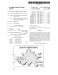
TEKTRONIX
INSTRUCTION MANUAL
Tektronix, Inc .
P .O . Box 500
Beaverton, Oregon
070-1752-01
97077
Serial Number
First Printing DEC 1974
questions
with your
Ti
Ell,
are warranted,
ship, for one year . i',o-, y
~ry ,.farranty should be taken up
He~rj F-igineer or representative .
All requests IL directed to znp
assure you he lastesi
in your area,
or
service . Please icOLidle the. instrument Type
P-ri' Number arm Seiia! Number with all -~-quesls l(, . parts
or service .
Specifications and price change privileges reserved .
Copyright , 1974, new material 1975, by Tektronix, Inc .,
Beaverton, Oregon . Printed in the United States of
America . All rights reserved . Contents of this publication
may not be reproduced in any form without permission of
Tektronix, Inc .
U .S .A . and foreign Tektronix products covered by U .S .
and foreign patents and/or patents pending .
TEKTRONIX is a registered trademark of Tektronix, Inc .
7B92A Operators
TABLE OF CONTENTS
PAGE
ii
List of Illustrations
List of Tables
SECTION 1
SPECIFICATION
1-1
Electrical Characteristics
1-1
Environmental
SECTION 2
Physical
1-5
OPERATING INSTRUCTIONS
2-1
Installation
2-1
Front-Panel Controls, Connectors, and Indicators
Main Triggering Controls
Sweep Controls
Delayed Triggering Controls
Front-Panel Inputs
2-2
2-4
2-4
2-5
2-5
General Operating Information
2-8
Applications
2-13
Main Triggering
Main Trigger Modes
Main Trigger Coupling
Main Trigger Source
Input Impedance
Trigger Slope
Trigger Level
Selecting Sweep Rates
Time Measurement
Display Modes
Delay Time Multiplier
Delayed Sweep Triggering
Mainframe Operating Modes
Time Duration Measurements
Determining Frequency
Risetime Measurements
Delayed Sweep Measurements
Delayed Sweep Magnification
Triggered Delayed Sweep Magnification
Displaying Complex Signals Using Delayed Sweep
Pulse Jitter Measurements
REV . A, NOV . 197 5
2-2
Familiarization Procedure
Setup Procedure
Sweep Functions
Triggering Functions
SECTION 3
1-5
OPTIONS
2-5
2-6
2-6
2-8
2-8
2-8
2-9
2-9
2-9
2-11
2-11
2-11
2-11
2-12
2-12
2-13
2-13
2-13
2-14
2-14
2-15
2-16
2-16
2-17
3-1
7B92A Operators
LIST OF ILLUSTRATIONS
FIGURE NO .
PAGE
1-1
7B92A Dual Time Base .
2-1
Location of Variable and Mainframe Selector multi-pin
connectors .
2-1
2-2
Location of release latch.
2-2
2-3
Front panel controls and connectors .
2-3
2-4
Effect of LEVEL control and SLOPE switch on crt display .
2-10
2-5
Area of graticule used for most accurate time measurements .
2-11
2-6
Typical alternate sweep display.
2-12
2-7
Measuring the time duration between points on a waveform .
2-13
2-8
Measuring risetime .
2-14
2-9
Measuring time difference using delayed sweep.
2-15
2-10
Using delayed sweep for magnification.
2-16
2-11
Displaying a complex signal using delayed sweep.
2-17
2-12
Measuring pulse jitter .
2-18
iv
7B92A Operators
LIST OF TABLES
TABLE NO .
PAGE
1-1
Electrical Characteristics
1-1
1-2
Environmental
1-5
1-3
Physical
1-5
2-1
Risetime Measurements
2-14
7B92A Operators
175215
7B92A Features
The 7B92A Dual Time Base unit provides normal, delayed, intensified, and al et nate sweep operation for Tektronix 7000Series Oscilloscopes . Calibrated sweep rates from 0 .2 second to 0 .5 nanosecond and triggering to 500 megahertz are provided . The 7B92A is intended for use with high frequency 7000 Series Oscilloscope systems ; however, most 7B92A
functions are compatible with all 7000-Series Oscilloscopes .
Other features include lighted pushbutton switches, compatibility with indicator oscilloscopes having an alphanumeric readout system, and 0 to 9 .8 times continuous sweep delay . A VARIABLE control allows continuously variable sweep rates between calibrated steps . Also, when operating in the AUTO BRAIN TRIGGERING MODE, a bright base line is displayed in
the absence of a trigger signal .
Fig. 1-1 . 7B92A Dual Time Base .
iv
REV . A, NOV. 1975
Section 1-7B92A Operators
SPECIFICATION
This instrument will meet the electrical characteristics listed under Performance Requirement in Table 1-1, following complete calibration . The following electrical characteristics apply over an ambient temperature range of OOC to +500C, except
as otherwise indicated. Warmup time for given accuracy is 20 minutes.
TABLE 1-1
Electrical Characteristics
Characteristic
Supplemental
Information
Performance Requirement
MAIN TRIGGERING
Trigger Sensitivity
Triggering Frequency
Range
Operating in AUTO, NORM, or
SINGLE SWEEP MODE
Minimum Triggering
Signal Required
INT2
(div)
EXT3
(mV)
COUPLING
AC
30 Hz to 20 MHz
20 MHz to 500 MHz
0.5
1 .0
100
500
AC LF REJ'
30 Hz to 20 MHz
20 MHz to 500 MHz
0.5
1 .0
500
AC H F REJ
30 Hz to 50 H z
0.5
100
DC
Dc to 20 MHz
20 MHz to 500 MHz
0.5
1 .0
100
500
AC
AC LF REJ
DC
100 MHz to 500 MHz
0.5
100
AC HF REJ
Not recommended for HF
SYNC mode
100
Operating in HF SYNC MODE
Use NORM or SINGLE
SWEEP MODE for signals
below about 30 Hz
External Trigger Input
Level Range
EXT
At least + and -3 .5 volts
EXT - 10
At least + and -35 volts
Not applicable in HF SYN(
MAIN TRIGGERING
Mode
Maximum Safe Input
'
1 M52 Input
250 V (dc + peak ac)
5052 Input
1 W average (7 V rms)
Will not trigger on the sine waves of 8 div amplitude or less (internal), or 3 V or less (external) at 60 Hz or below.
z For Internal Triggering only, the specified -3 dB frequency of the Vertical System replaces any frequencies in the above table when the number in the table is greater than the -3 dB frequency of the Vertical System .
s Triggering signal amplitude requirements increased by factor of 10 for EXT _ 10 operation.
REV. A, APR . 1975
Specification-71392A Operators
TABLE 1-1 (cont .)
Electrical Characteristics
Characteristic
Supplemental
Information
Performance Requirement
MAIN TRIGGERING (cont.)
Input R and C
Approximately 1 MR
paralleled by approximately 20 pF
1 MR Input
50 SZ Input
50 R within 7%
Resistance
0.1 p-p (using 1 GHz Reflectometer)
Reflection Coefficient (Time
Domain)
Trigger Jitter
Internal or External
50 ps or less at 500 MHz
DELAYED TRIGGERING
Trigger Sensitivity
Triggering Frequency
Range
Minimum Triggering
Signal Required
INTO
(div)
EXT
(m V)
COUPLING
AC
30 Hz to 20 MHz
0.5
100
20 MHz to 500 MHz
1 .0
500
DC
Dc to 20 MHz
0.5
100
20 MHz to 500 MHz
1 .0
500
Trigger Jitter
Internal or External
50 ps or less at 500 MHz
External Trigger Input
Level Range
EXT
Maximum Safe Input
1 MR Input
50 S2 Input
Input R and C
1 MR Input
At least +3 .5 V to -3 .5 V
250 V (dc + peak ac)
1 W average (7 V rms)
Approximately 1 MR
paralleled by approximately 20 pF
"The specified -3 dB frequency of the Vertical System replaces any frequencies in the above table when the number in the table is greater than
the -3 dB frequency of the Vertical System .
REV. A, APR . 1975
Specification-71392A Operators
TABLE 1-1 (cont .)
Electrical Characteristics
Performance Requirement
Characteristic
Supplemental
Information
DELAYED TRIGGERING (cont .)
Input R and C (cont .)
50 St Input
Resistance
50 S2 within 7%
Reflection Coefficient (Time
Domain)
0 .1 p-p (using 1 GHz
Reflectometer)
NORMAL, ALT (Delayed Sweep
Trace) and DLY'D SWEEP
Sweep Rates
0 .2 s/div to 0 .5 ns/div in 27 calibrated steps
Sweep Accuracy
Measured in 7900-Series Oscilloscope
Over Center 8 Div
+15 ° C to +35 ° C
Selected by TIME/DIV
switch . Steps in a 1-2-',
sequence
0 ° C to +50 ° C
.2 s/Div to 20 ns/Div
Within 2%
Within 3%
10 ns/Div to 5 ns/Div
Within 3%
Within 4%
2 ns/Div to 1 ns/Div
Within 4%
Within 5%
.5 ns/Div
Within 5%
Within 6%
.2 s/Div to 10 ns/Div
Within 5%
Within 5%
5 ns/Div to .5 ns/Div
Within 10%
Within 10%
Over Any 2 Div Portion Within
Center 8 Div
Variable Sweep Rate
Continuously variable between calibrated sweep rates .
INTENSIFIED SWEEP (Delaying
Sweep Trace of ALT Sweep Display)
Sweep Rates
0 .2 s/div to 10 ns/div in 23 calibrated steps
Sweep Accuracy
Measured in 7900-Series Oscilloscope
Over Center 8 Div
.2 s/Div to 20 ns/Div
10 ns/Div
Over Any 2 Div Portion Within
8 Div
REV . A, NOV . 1975
+15° C to +35° C
Extends sweep rate to
at least 0 .5 s . VARIABLE control internally
switchable between De
laying and Delayed
Sweeps
Selected by TIME/DIV
OR IDLY TIME switch .
Steps in a 1-2-5 sequen
0 ° C to +50 ° C
Within 2%
Within 3%
Within 3%
Within 4%
Within 5%
Within 5%
1-3
Specification-7B92A Operators
TABLE 1-1 (cont .)
Electrical Characteristics
Characteristic
Performance Requirement
Supplemental
Information
INTENSIFIED SWEEP (Delaying Sweep
Trace of ALT Sweep Display) (cont .)
Variable Sweep Rate
Continuously variable between calibrated sweep
rates
Trace Separation
Intensified sweep can be positioned at least 3 .5
div above the delayed sweep
Alt Off
Intensified sweep of the delaying sweep is displayed when the TIME/DIV switch is pulled
out and rotated clockwise, and the TRACE
SEP control is in ALT OFF position
Extends sweep rate to at
least 0 .5 s . Variable control internally switchable
between Delaying and
Delayed Sweeps
Allow Intensified Mode of
operation
VARIABLE TIME DELAY
Delay Time Range
DLY TIME/DIV Settings
.2 s/Div to 10 ns/Div
0 to 9 .8 times the IDLY TIME switch setting (0
to 1 .96 s)
Differential Delay Time Measurement
Accuracy
+15 ° C to +35 0 C
.2 s/Div to .1 ps/Div
Both DELAY TIME MULT
dial settings at 0 .50 or greater
Within 0 .75% of measurement +0 .25% of full
scale
One or Both DELAY TIME
MULT dial settings less than
0 .50
Within 0 .75% of measurement +0 .5% of full scale
+ 5 ns
Full scale is 10 times the
TIME/DIV OR IDLY TIME
setting
50 ns/Div to 10 ns/Div
Both delay times equal to or
greater than 25 ns
Within 1 .0% of measurement +0 .5% of full scale
One of both delay times less
than 25 ns
Within 1 .0% of measurement +1 .0% of full scale
+ 5 ns
Delay Time Jitter
Jitter specification does not
apply to the first 2% of the
maximum available delay
time (DELAY TIME MUL-1
dial setting less than 0 .20)
1 part or less in 50,000 of the maximum available
delay time (10 times the TIME/DIV OR DLY
TIME switch setting)
20 ps/Div to 10 ns/Div
1 part or less in 50,000 of the maximum available
delay time (10 times the TIME/DIV OR IDLY
TIME switch setting + 0 .5 ns)
1-4
0.2 s/Div to 50 its/Div
REV . B, NOV . 1975
Specification-7B92A Operators
TABLE 1-3
Physical
TABLE 1-2
Environmental
Refer to the Specification for the associated oscilloscope .
Net Weight
Dimensions
3.062 Ibs (1 .372 Kg)
i
See Fig . 1-2, Dimensional Drawing
OVERALL DIMENSIONS
(MEASURED AT MAXIMUM POINTS)
0
0
0
0
0
0
0
0
0
0
0
0
0
" aoo
0 000
I~- (7,
5 .0
112. 7)
C
14 .6
(37,1)
2.8
1)
NOTE
DIMENSIONS ARE GIVEN WITH TOP FIGURE IN
INCHES AND BOTTOM FIGURE IN CENTIMETERS .
Fig . 1- 2 .
1752-14
Dimensional drawing .
Section 2-7B92A Operators
OPERATING INSTRUCTIONS
The 7B92A Dual Time-Base Plug-In Unit operates with a Tektronix 7000-Series Oscilloscope and a 7A-Series Amplifier plugin unit to form a complete high-frequency oscilloscope system . This section describes the operation of the front-panel controls and connectors, provides general operating information, an Operating Check-Out procedure, and basic applications for
this instrument .
NOTE
The ALT OFF position, which allows the Intensified mode of operation, is applicable to instruments
SN B060000 and up .
INSTALLATION
The 7B92A is designed to operate in the horizontal plug-in
compartment of the oscilloscope . This instrument can also
be installed in a vertical plug-in compartment to provide a
vertical sweep on the crt . However, when used in this manner, there are no internal triggering or retrace blanking provisions, and the unit may not meet the specifications given
in Section 1 .
Before proceeding with installation, check the settings of
the Time/Div Variable Selector multi-pin connector and
the Mainframe Selector multi-pin connector (see Fig . 2-1) .
The Time/Div Variable Selector determines whether the
front-panel Time/Div VARIABLE control operates in conjunction with the delaying or delayed sweeps . The Mainframe Selector adapts the 7B92A to the oscilloscope mainframe being used . The two mainframe selections are :
(1) 7800 and 7900-Series Oscilloscopes .
(2) All other 7000-Series Oscilloscopes .
NO TE
The 7B71 will not delay the 7B92A for displaying
alternating Delaying and Delayed sweeps. Instead,
it causes a sweep lock-up to occur under the following conditions; with the 7B71 in the A Horizontal
compartment, and the 7B92A in the B Horizontal
compartment, the sweep locks up if the 7B92A is
in its Alternate mode and the Mainframe Horizontal
Mode is Alt. Lock-up can be avoided by changing
the Mainframe Horizontal Mode to Chop or B. This
allows both 7B92A sweeps to be displayed.
To install the 7B92A in a plug-in compartment, push it in
until it fits firmly into the compartment . The front panel
of the 7B92A should be flush with the front panel of the
oscilloscope . Even though the gain of the oscilloscope is
standardized, the sweep calibration of the 7B92A should
be checked when installed . The procedure for checking
the unit is given under Sweep Calibration in the Operating
Checkout procedure in this section .
1752-02
Fig . 2-1 . Location of Variable and Mainframe Selector multi-pin connectors.
REV . B, NOV . 1975
Operating Instructions-71392A Operators
To remove the 7B92A, pull the release latch (see Fig. 2-2)
to disengage the unit from the oscilloscope, and pull it out
of the plug-in compartment .
SLOPE Switch
Permits triggering on the positive or negative slope of
the trigger signal (except in HF SYNC) .
TRIG'D Indicator
FRONT-PANEL CONTROLS,
CONNECTORS, AND INDICATORS
All controls, connectors, and indicators required for the
operation of the 7B92A, except the Time/Div Variable and
Mainframe Selectors, are located on the front panel . A brief
description of the front-panel controls, connectors, and
indicators is given here . More detailed information is given
under General Operating Information . Fig . 2-1 shows the
Time/Div Variable and Mainframe Selectors . Fig . 2-3 shows
the front-panel controls, connectors, and indicators .
Main Triggering Controls
LEVEL Control
Selects amplitude point on trigger signal where sweep
triggering occurs when the Main Triggering Mode AUTO, NORM, or SINGLE SWEEP switches are pressed .
When the Main Triggering Mode HF SYNC switch is
pressed, the LEVEL control adjusts the frequency of
the trigger generator to synchronize with the frequency (or sub-harmonic) of the triggering signal to provide a stable display .
When lit, indicates that the sweep is triggered and will
produce a display with correct setting of the POSITION control and the controls on the associated Amplifier plug-in unit(s) and oscilloscope .
MODE Switches
Select the desired main triggering mode . Selected
mode is indicated by lighted pushbutton .
AUTO : Selects a triggered sweep initiated by the applied trigger signal at a point determined by the LEVEL control and SLOPE switch when the trigger signal repetition rate is above 30 hertz and within the
frequency range selected by the COUPLING switches .
When the LEVEL control is outside the amplitude
range, the trigger repetition rate is outside the frequency range selected by the COUPLING switches,
or the trigger signal is inadequate, the sweep free-runs
to provide a reference trace .
HF SYNC : Sweep initiated by trigger signals with repetition rates above 100 megahertz and within the
range selected by the COUPLING switch . Stable display can be obtained when the LEVEL control adjusts
the frequency of the trigger generator to the frequency
(or subharmonic) of the trigger signal . When the LEVEL control is adjusted to frequencies between subharmonics, the sweep free-runs .
NORM : Sweep initiated by the applied trigger signal
at a point selected by the LEVEL control and SLOPE
switch over the frequency range selected by the COUPLING switches . Triggered sweep can be obtained
only over the amplitude range of the applied trigger
signal . When the LEVEL control is either outside the
amplitude range, the trigger repetition rate is outside
the frequency range selected by the COUPLING switches, or the trigger signal is inadequate, there is no
trace .
SINGLE SWEEP-RESET : When the SINGLE SWEEPRESET pushbutton switch is pressed, a single trace
will be presented when the next trigger pulse is received . The SINGLE SWEEP-RESET pushbutton remains lit until a trigger is received and the sweep is
completed . The SINGLE SWEEP-RESET pushbutton
switch must be pressed again before another sweep
can be displayed .
RELEASE
LATCH
Fig. 2-2 . Location of release latch .
2-2
1752 -1 6 'I
COUPLING Switches
Select trigger signal coupling . Selected coupling is indicated by lighted pushbutton .
REV . B, NOV . 1975
Operating Instructions-71392A Operators
AC : Rejects do and attenuates ac signals below approximately 30 hertz . Accepts signals between 30 hertz and
500 megahertz .
AC LF REJ : Rejects do and attenuates signals below
30 kilohertz . Accepts signals between 30 kilohertz and
500 megahertz .
AC HF REJ : Rejects do and attenuates signals above
50 kilohertz . Accepts signals from 30 hertz to 50 kilohertz .
DC : Accepts all signals from do to 500 megahertz .
SOURCE Switches
Select the triggering source . Selected source is indicated by lighted pushbutton .
INT : Trigger signal obtained internally from Amplifier plug-in unit of oscilloscope .
LINE : Trigger signal obtained internally from the
line voltage applied to the oscilloscope .
EXT : Trigger signal obtained from an external source
applied to the MAIN TRIG IN connector .
1752-17
Fig . 2-3 . Front-panel controls and connectors.
REV . A, NOV . 1975
2- 3
Operating Instructions-71392A Operators
SOURCE Switches (cont .)
VARIABLE
EXT= 10 : Trigger signal obtained from an external
source applied to the MAIN TRIG IN connector . In
this position, the external signal is attenuated before
it is applied to the trigger circuit .
Two-position switch actuated by the VARIABLE control to select calibrated or uncalibrated sweep rates .
In the CAL position (knob in) the VARIABLE control is inoperative and the sweep rate is calibrated .
When pressed and released, the knob moves out to
activate the VARIABLE control for uncalibrated
sweep rates . The sweep rate in each TIME/DIV switch
position can be reduced to at least the sweep rate of
the next slower position . The VARIABLE control
will operate with either the delaying or delayed sweep
by means of the internal Time/Div Variable Selector .
Sweep Controls
TIME/DIV OR DLY TIME
Selects the basic sweep rate for normal sweep operation and selects the delay time (multiplied by the DELAY TIME MULT dial setting) when operating in the
Alternate or Delayed sweep modes . The VARIABLE
control must be in the CAL (knob in) position for calibrated sweep rate .
DLY'D Time/Division
Selects the delayed sweep rate for operation in Delayed and Alternate sweep modes . The VARIABLE control must be in the CAL (knob in) position for calibrated sweep rate .
Four display modes can be selected by the following
switch settings :
Normal Sweep : A normal sweep is selected when the
TIME/DIV OR IDLY TIME switch and the DLY'D
Time/Division switches are locked together at the same
sweep rate . The DLY'D Time/Division knob must be
pressed in for normal sweep mode . Calibrated sweep
rates from 0 .2 second/division to 0 .5 nanosecond/division can be selected .
ALT Sweep : The Alternate mode is selected when the
DLY'D Time/Division switch is pulled out and rotated
clockwise and the TRACE SEP control is turned clockwise from the ALT OFF position . In this mode, the
delaying sweep is displayed (with an intensified zone
during the time that the delayed sweep runs) alternately with the delayed sweep .
Intensified Sweep : The intensified sweep mode (Intens)
is selected when the DLY'D Time/Division switch is
pulled out, and rotated to the desired sweep rate faster
than the TIME/DIV or IDLY TIME switch setting, and
the TRACE SEP control is rotated counterclockwise
to the ALT OFF position (see Fig . 2-3) . In this mode,
a portion of the delaying sweep is intensified during
the time that the delayed sweep generator runs .
DLY'D Sweep : The delayed sweep mode is selected
when the DLY'D Time/Division switch is pulled out,
rotated for the desired delayed sweep rate, and then
pushed in . In this mode, the delayed sweep is dis
played at a rate determined by the DLY'D Time/Division switch at the end of each delay period, as selected by the TIME/DIV OR IDLY TIME switch and the
DELAY TIME MULT dial setting .
2-4
POSITION Control
Positions the display horizontally on the graticule .
CONTRAST Control
Varies the relative brightness of the intensified portion
of the delaying trace when in the Alternate mode .
TRACE SEP/ALT OFF Control
This control vertically positions the delaying sweep
display up to 3 .5 divisions above the delayed sweep
display when in the Alternate mode . The ALT OFF
position allows the Intensified sweep mode of operation, permitting the display of an intensified portion
of the delaying sweep .
INTENSITY Control
Varies the intensity of the Intensified sweep only
when operating in the INTENS or ALT mode .
SWP CAL Adjustment
Screwdriver adjustment sets the basic timing of the
7B92A to compensate for slight differences in input
sensitivity when changing indicator oscilloscopes .
DELAY TIME MULT Dial
Provides variable delay of 0 to 9 .8 times the basic delay time selected by the TIME/DIV OR IDLY TIME
switch .
Delayed Triggering Controls
LEVEL Control
Determines the delayed trigger mode and the delayed
trigger level .
RUNS AFTER DELAY TIME (LEVEL control turned
fully clockwise into detent) : Delayed sweep runs immediately following the delay time selected by the
TIME/DIV OR IDLY TIME switch and the DELAY
TIME MULT dial . Delayed SLOPE, COUPLING, and
SOURCE functions are inoperative .
Delayed Sweep Triggerable : When the Delayed Triggering LEVEL control is turned counter-clockwise
out of detent, the delayed sweep is triggerable . The
Delayed Triggering LEVEL control can now be rota-
REV . B, NOV . 1975
Operating Instructions-71392A Operators
LEVEL Control (cont .)
DLY'D TRIG IN Connector
ted to select the amplitude point on the trigger signal
at which the delayed sweep is triggered . In the Delayed
Sweep Triggerable mode, the delayed SLOPE, COUPLING, and SOURCE functions are activated .
Serves as an external trigger input for the delayed triggering circuit when the Delayed Triggering SOURCE
switch is set to EXT .
SLOPE Switch
Two-position switch to select the slope of the trigger
signal which starts the delayed sweep .
+ : The delayed sweep can be triggered on the positive
slope of the trigger signal .
- : The delayed sweep can be triggered on the negative slope of the trigger signal .
18
SOURCE Switch
Two-position pushbutton switch to select the source
of the delayed trigger signal .
INT : The delayed trigger signal is obtained from the
vertical amplifier of the oscilloscope .
EXT : The delayed trigger signal is obtained from an
external source connected to the DLY'D TRIG IN
connector.
Do not exceed 7 volts (rms) of external
signal when 50 SZ termination is selected.
FAMILIARIZATION PROCEDURE
The following procedure may be used for familiarization
or as a check of basic instrument operation . The procedure
is divided into two parts, Sweep Functions and Triggering
Functions . A complete operating check of the 7B92A functions can be made by performing both parts, or each part
may be performed separately . If performing the Familiarization Procedure reveals a malfunction or improper calibration, first check the operation of the associated plug-in units ;
then refer to the 7B92A Service manual .
NO TE
For optimum high-frequency performance, the 7B92A
should be installed in an oscilloscope system with similar frequency and sweep-rate capabilities.
COUPLING Switch
Two-position pushbutton switch to determine the
method of coupling the trigger signal to the delayed
trigger circuit .
AC : Rejects do and attenuates signals below 30 hertz .
Accepts trigger signals from 30 hertz to 500 megahertz .
DC : Accepts trigger signals from do to 500 megahertz .
Front-Panel Inputs
Setup Procedure
1 . Install the 7B92A in a horizontal compartment of the
oscilloscope .
2 . Install the Amplifier plug-in unit in a vertical compartment .
3. Turn on the oscilloscope and allow at least 20 minutes
warmup .
4 . Set the 7B92A controls as follows :
MAIN TRIG IN Connector
Serves as an external trigger input for the main triggering circuit when the Main Triggering Source EXT or
EXT - 10 pushbutton switches are pressed .
TERM Switch
Two-position pushbutton switch to select 50 ohms (out
position) or 1 megohm (in position) input impedance
for the MAIN TRIG IN and DLY'D TRIG IN connectors .
REV . B, NOV . 1975
Main Triggering
SLOPE
(+)
MODE
AUTO
COUPLING
AC
SOURCE
INT
Delayed Triggering
LEVEL
RUNS AFTER DELAY
TIME
2-5
Operating Instructions-71392A Operators
Delayed Triggering (cont .)
SLOPE
(+)
COUPLING
AC
SOURCE
INT
8 . Rotate the INTENSITY control and note that it varies
the intensity of the delaying sweep .
9 . Rotate the CONTRAST adjustment for adequate identification of the intensified portion of the delaying sweep when
alternating with delayed sweep .
NO TE
Sweep Controls
POSITION
Midrange
INTENSITY
As desired
TIME/DIV OR
IDLY TIME
1 ms
DLY'D Time/Division
1 ms (knob in)
VARIBLE
CAL
Time/Div Variable
Selector (Internal)
Delayed Sweep
DELAY TIME MULT
1 .00
TRACE SEP
Midrange
5 . Set the oscilloscope to display the plug-in units and adjust for a well defined display . See oscilloscope and Amplifier
plug-in unit instruction manuals for detailed operating instructions .
Sweep Functions
NORMAL SWEEP. Perform the following procedure to obtain a normal sweep and demonstrate the function of the
related sweep controls :
1 . Perform the Setup Procedure .
2 . Connect a 4 volt, 1 kilohertz signal from the oscilloscope
Calibrator to the Amplifier plug-in unit Input .
3 . Adjust the Amplifier plug-in unit Volts/Division switch
for two divisions of display .
4 . Rotate the Main Triggering LEVEL control for a stable
display .
5 . Rotate the POSITION control and note that the trace
moves horizontally .
6 . Check the crt display for one complete cycle per division .
If necessary, adjust the SWP CAL screwdriver adjustment for
one complete cycle per division over the center 8 graticule
divisions . Be sure that the timing of the Calibrator signal is
accurate within 0 .5%.
When operating in the Intensified Mode, the intensified zone is controlled by the intensity of the test
oscilloscope, instead of the 7B92A Contrast and
Intensity controls .
10 . Rotate the TRACE SEP control to vertically position
the delaying sweep trace with respect to the delayed sweep
trace . With the TRACE SEP control in the ALT OFF position, only the Intensified sweep will be displayed .
11 . Rotate the DELAY TIME MULT dial and note that the
amount of delay time before the intensified portion of the
display is controlled by the DELAY TIME MULT dial .
12 . Press the DLY'D Time/Division switch in for the Delayed sweep mode . Note the delayed display with sweep rate
determined by the DLY'D Time/Division switch .
13. Press and release the VARIABLE control . Rotate the
VARIABLE control and note that the sweep rate indicated
by the DLY'D Time/Division switch can be varied to at
least the sweep rate of the next adjacent position (0 .2 ms) .
The internal Time/Div Variable Selector must be set to
Delayed Sweep position . Return the VARIABLE control
to the CAL position (knob in) .
Triggering Functions
MAIN AND DELAYED TRIGGERING . Perform the following procedure to obtain a triggered alternate, normal,
or delayed sweep and demonstrate the function of the related controls :
14 . Perform the Set Up Procedure . Connect the 1 kilohertz
Calibrator signal from the oscilloscope to the Amplifier plugin unit Input and adjust for about 4 divisions of vertical display .
15 . Set the DLY'D Time/Division switch and the TIME/
DIV OR IDLY TIME switch to 1 ms, and press in the DLY'D
Time/Division knob (Normal sweep mode) . Rotate the
Main Triggering LEVEL control for a stable display .
ALTERNATE AND DELAYED SWEEP . Perform the following procedure to obtain alternate-delayed sweeps and
demonstrate the function of the related sweep controls :
16 . Check that a stable display can be obtained with the
Main Triggering COUPLING switch set to AC, AC HF REJ,
and DC, for both the positive and negative positions of the
SLOPE switch (Main Triggering LEVEL control may be adjusted as necessary to obtain a stable display) . Remove all
connections from the oscilloscope system .
7 . Pull out the DLY'D Time/Division knob and rotate clockwise to 0 .1 ms for the Alternate sweep mode . Note both an
intensified trace and a normal-intensity delayed sweep trace
on the crt . Increased oscilloscope intensity may be required
for viewing the delayed sweep .
17 . Connect a 0 .4 volt, 1 kilohertz signal from the oscilloscope Calibrator to the Amplifier plug-in unit and to the
MAIN TRIG IN connector . Set the Main Triggering SOURCF
switch to EXT . Set the Amplifier plug-in unit Volts/Div
switch for about 4 divisions of display . Check that a stable
2-6
REV . A, NOV . 1975
Operating Instructions-71392A Operators
display can be obtained with the Main Triggering COUPLING
switch set to AC, AC HF REJ, and DC, for both the positive
and negative positions of the SLOPE switch (Main Triggering
LEVEL control may be adjusted as necessary for a stable
display) .
23 . Check that a stable display can be obtained with the
Delayed Triggering COUPLING switch set to AC and DC
for both the (+) and (-) positions of the SLOPE switch
(Delayed Triggering LEVEL control may be adjusted as
necessary for a stable display) .
18 . Change the Main Triggering SOURCE switch to EXT
10. Set the oscilloscope Calibrator for 4 volts at 1 kilohertz and adjust the Amplifier plug-in unit Volts/Div switch
for about 4 divisions of display . Check that a stable display
can be obtained with the Main Triggering COUPLING switch
set to AC, AC HF REJ, and DC, for both the positive and
negative positions of the SLOPE switch (Main Triggering
LEVEL control may be adjusted as necessary to obtain a
stable display) . Remove all connections from the oscilloscope system .
24 . Change the Delayed Triggering SOURCE switch to
EXT . Connect a 0 .4 volt, 1 kilohertz signal from the oscilloscope Calibrator to the DLY'D TRIG IN connector . Check
that a stable display can be obtained with the Delayed Triggering COUPLING switch set to AC and DC, for both the
(+) and (-) positions of the SLOPE switch (Delayed Triggering LEVEL control may be adjusted as necessary for a
stable delayed sweep display) .
19 . Set the Main Triggering COUPLING switch to AC and
SOURCE switch to INT. Connect a 1 kilohertz Calibrator
signal from the oscilloscope to the Amplifier plug-in unit
Input and adjust for about 4 divisions of display amplitude .
Adjust the Main Triggering LEVEL control for a stable display . Set the MODE switch to NORM and check for a stable display . Change the MODE switch to AUTO and adjust
the LEVEL control for a free-running display . Change the
MODE switch to NORM and check for no display .
20 . Adjust the Main Triggering LEVEL control for a stable
display . Change the Main Triggering MODE switch to SINGLE SWEEP. Press the RESET button and check for one
sweep as the RESET button is pressed . Remove the 1 kilohertz signal from the Amplifier plug-in unit and press the
RESET button . Check for no display and READY light on .
Connect the 1 kilohertz signal to the Amplifier plug-in unit
Input and check for one sweep as the signal is applied .
Remove all connections from the oscilloscope system .
21 . Set the Main Triggering MODE switch to AUTO and
SOURCE switch to AC . Turn the Delayed Triggering LEVEL control fully clockwise to the RUNS AFTER DLY
TIME position . Pull out the DLY'D Time/Division switch
and rotate to 0 .2 ms (Alternate mode) . Connect a 0 .4 volt,
1 kilohertz signal from the oscilloscope Calibrator to the
Amplifier plug-in unit Input and adjust for about 2 divisions
of display amplitude . Rotate the Main Triggering LEVEL
control for a stable intensified display . The INTENSITY
control may need to be adjusted to view the intensified display . Rotate the DELAY TIME MULT dial and note that
the delay time before the intensified portion of display is
continuously variable .
22 . Set the Delayed Triggering SLOPE, COUPLING, and
SOURCE switches to (+), AC, and I NT . Rotate the Delayed Triggering LEVEL control counterclockwise out of the
detent and adjust for a stable display . Rotate the DELAY
TIME MULT dial and note that the intensified sweep does
not start at the completion of the delay time but waits for
the next trigger pulse .
REV . A, NOV . 1975
HIGH-FREQUENCY SYNCHRONIZATION . Perform the
following procedure to obtain a triggered alternate, normal,
or delayed sweep with a 100 megahertz to 500 megahertz
input signal :
NO TE
To check HF SYNC operation, a signal source frequency between 100 megahertz and 500 megahertz is required. If a 100 to 500 megahertz signal source is not
desired to check the HF SYNC operation, the last two
steps of this procedure may be deleted.
25 . Change the Main Triggering MODE switch to HF SYNC .
Connect a high-frequency signal source (100 to 500 megahertz) to the Amplifier plug-in unit Input and adjust for 4
divisions of vertical deflection . Adjust the TIME/DIV OR
DLY TIME switch and DLY'D Time/Division switch for
about 6 cycles of display . Rotate the Main Triggering LEVEL control throughout its range and note that the sweep
is alternately stable, then free-running, several times during
the rotation (stable display indicates that the trigger-generator frequency is adjusted to a subharmonic of the trigger
signal frequency) . Check that stable displays can also be
obtained with the Main Triggering COUPLING switch set
to AC, AC LF REJ, and DC (Main Triggering LEVEL control may be adjusted, as necessary for a stable display) .
26 . Pull out the DLY'D Time/Division switch, rotate it to
the next fastest sweep rate from the setting of the TIME/
DIV OR IDLY TIME switch (Alternate mode) . When the
LEVEL control is in the detent (RUNS AFTER DELAY
TIME) the display should be stable . Rotate the LEVEL
control counterclockwise out of the detent and adjust for
a stable display . Check that stable crt displays can be obtained with the Delayed Triggering COUPLING switch set
to AC and DC . Disconnect the high-frequency signal from
the oscilloscope system .
2-7
Operating Instructions-71392A Operators
GENERAL OPERATING INFORMATION
Main Triggering
The Main Triggering MODE, COUPLING, and SOURCE
pushbutton switches are arranged in a sequence which
places the most-often used position at the top of each series
of pushbuttons . With this arrangement, a stable display can
usually be obtained by pressing the top pushbuttons : AUTO,
AC, and INT . When an adequate trigger signal is applied
and the LEVEL control is set correctly, the TRIG'D indicator will light . If the TRIG'D indicator is not lit : (1) the
LEVEL control is at a setting outside the range of the trigger signal from the Amplifier plug-in unit, (2) the trigger
signal is inadequate, or (3) the trigger-signal frequency is
below the lower frequency limit of the COUPLING switch
position . If the desired display is not obtained with these
pushbuttons, other selections must be made . Refer to the
following discussions or the instruction manuals for the
oscilloscope and Amplifier plug-in unit for more information .
Main Trigger Modes
The MODE pushbutton switch selects the mode in which
the main sweep is triggered .
AUTO . The AUTO pushbutton provides a triggered display
with the correct setting of the LEVEL control (see Trigger
Level discussion) whenever an adequate trigger signal is applied . The TRIG'D indicator lights when the display is triggered .
When the trigger repetition rate is outside the frequency
range selected by the COUPLING switch or the trigger signal
is inadequate, the sweep free-runs at the sweep rate indicated
by the TIME/DIV OR DLY TIME switch (TRIG'D indicator
off) . An adequate trigger signal ends the free-running condition and a triggered display is presented . When the LEVEL
control is at a setting outside the amplitude range of the trigger signal, the sweep also free runs at the sweep rate indicated by the TIME/DIV OR DLY TIME switch . This type of
free-running display can be useful when it is desired to measure only the maximum peak-to-peak amplitude of a signal
without observing the waveshape (such as in bandwidth
measurements) .
HF SYNC . The HF SYNC pushbutton permits stable displays of repetitive signals with only 0 .5 division of internal
trigger signal (100 millivolts external signal) required for
frequencies between 100 megahertz and 500 megahertz .
A triggered display is obtained when the LEVEL control adjusts the frequency of the trigger generator to the frequency
or subharmonic of the trigger signal . Stable displays may be
obtained several times between the limits of the LEVEL control, depending on the amplitude and frequency of the trigger signal . The LEVEL control should be set for optimum
display . (In the High-Frequency Synchronization mode,
the display is not necessarily stable when the TRIG'D indicator is lit .)
2- 8
When the LEVEL control is adjusted between subharmonics
of the trigger signal frequency, the trigger repetition rate is
below 100 megahertz or outside the frequency range selected by the COUPLING switch, or the trigger signal amplitude
is inadequate, the sweep free-runs at the sweep rate determined by the TIME/DIV OR DLY TIME switch .
NORM . The NORM pushbutton provides a triggered display
with the correct setting of the LEVEL control whenever an
adequate trigger signal is applied . The TRIG'D indicator
lights when the display is triggered .
The NORM trigger mode must be used to produce triggered
displays with trigger repetition rates below about 30 hertz .
When the TRIG'D indicator is off, no trace will be displayed .
SINGLE SWEEP . When the signal to be displayed is not repetitive or varies in amplitude, waveshape, or repetition rate,
a conventional repetitive type display may produce an unstable presentation . A stable display can often be obtained
under these circumstances by using the single-sweep feature
of this unit . The single-sweep mode is also useful to photograph non-repetitive or unstable displays .
To obtain a single-sweep display of a repetitive signal, first
obtain the best possible display in the NORM mode . Then,
without changing the other MAIN TRIGGERING controls,
press the SINGLE SWEEP RESET pushbutton . A single
trace is presented each time the pushbutton is pressed . Further sweeps cannot be presented until the SINGLE SWEEPRESET pushbutton is pressed again . If the displayed signal
is a complex waveform composed of pulses of varying amplitude, successive single-sweep displays may not start at
the same point on the waveform . To avoid confusion due
to the crt persistence, allow the display to disappear before
pressing the SINGLE SWEEP-RESET pushbutton again . At
fast sweep rates, it may be difficult to view the single-sweep
display . The apparent trace intensity can be increased by
reducing the ambient light level or using a viewing hood as
recommended in the oscilloscope instruction manual .
When using the single-sweep mode to photograph waveforms,
the graticule must be photographed separately in the normal
manner to prevent over-exposing the film . Be sure the camera system is well protected against stray light, or operate the
system in a darkened room . For repetitive waveforms, press
the SINGLE SWEEP-RESET pushbutton only once for each
waveform unless the signal is completely symmetrical . Otherwise, multiple waveforms may appear on the film . For
random signals, the lens can be left open until the signal
triggers the unit . Further information on photographic techniques is given in the appropriate camera instruction manual .
Main Trigger Coupling
The Main Triggering COUPLING switches select the method
in which the trigger signal is connected to the trigger circuits .
Each position permits selection or rejection of some frequency components of the trigger signal which trigger the sweep .
REV . A, APR . 1975
Operating Instructions-71392A Operators
AC. The AC pushbutton blocks the do component of the
trigger signal . Signals with low-frequency components below about 30 hertz are attenuated . In general, ac coupling
can be used for most applications . However, if the signal
contains unwanted frequency components or if the sweep
is to be triggered at a low repetition rate or do level, one of
the other COUPLING switch positions will provide a better
display .
AC LF REJ . The AC LF REJ pushbutton rejects dc, and
attenuates low-frequency trigger signals below about 30
kilohertz . Therefore, the sweep is triggered only by the
higher-frequency components of the trigger signal . This
position is particularly useful for providing stable triggering
if the trigger signal contains line-frequency components .
Also, the AC LF REJ position provides the best alternatemode vertical displays at fast sweep rates when comparing
two or more unrelated signals .
AC HF REJ . The AC HF REJ pushbutton passes all lowfrequency signals between about 30 hertz and 50 kilohertz .
Dc is rejected and signals outside the above range are attenuated . When triggering from complex waveforms, this position is useful to provide a stable display of the low-frequency components . AC HF REJ Coupling should not be used
when operating in the HF SYNC triggering mode .
DC . The DC pushbutton can be used to provide stable triggering from low-frequency signals which would be attenuated in the other modes . It can also be used to trigger the
sweep when the trigger signal reaches a do level set by the
LEVEL control . When using internal triggering, the setting
of the Amplifier plug-in unit Position control affects the
triggering point .
component in a complex waveform . Line triggering cannot
be used when operating in the HF SYNC triggering mode .
EXT . The EXT pushbutton connects the signal from the
MAIN TRIG IN connector to the trigger circuit . The external signal must be time-related to the displayed waveform
for a stable display . An external trigger signal can be used
to provide a triggered display when the internal signal is too
low in amplitude for correct triggering, or contains signal
components on which triggering is not desired . It is also
useful when signal tracing in amplifiers, phase-shift networks,
wave-shaping circuits, etc . The signal from a single point in
the circuit can be connected to the MAIN TRIG IN connector through a probe or cable . The sweep is then triggered by
the same signal at all times and allows amplitude, time relationship, or waveshape changes of signals at various points
in the circuit to be examined without resetting the MAIN
TRIGGERING controls .
EXT= 10 . The EXT= 10 pushbutton operates the same as
described for EXT except that the external signal is attenuated . Attenuation of high-amplitude external trigger signals
is desirable to increase the effective range of the LEVEL
control .
Input- Impedance
The input impedance of the MAIN TRIG IN and DLY'D
TRIG IN connectors may be selected by the front-panel
TERM switch .
IN - 1 MS2 . The 1 MS2 position is suitable for most low.
and medium-frequency applications or when using a 10X
probe . The 1 MS2 position provide a high input impedance
for minimum loading on the trigger signal source .
Main Trigger Source
The Main Triggering SOURCE pushbutton switches select
the source of the trigger signal which is connected to the
main trigger circuits .
INT . The INT pushbutton connects the trigger signal from
the Amplifier plug-in unit . Further selection of the internal
trigger signal may be provided by the Amplifier plug-in unit
or oscilloscope ; see the instruction manuals for these in
struments for more information . For most applications,
the internal source can be used . However, some applications
require special triggering which cannot be obtained in the
INT position . In such cases, the LINE or EXT positions
of the SOURCE switches must be used .
LINE . The LINE pushbutton connects a sample of the
power-line voltage from the oscilloscope to the trigger circuit . Line triggering is useful when the input signal is timerelated (multiple or submultiple) to the line frequency . It
is also useful for providing a stable display of a line-frequency
OUT - 50 2 . The 5052 position is recommended for highfrequency applications requiring maximum overall bandwidth . The 50 ohm termination should be used when externally triggering from a 50 ohm system .
Trigger Slope
The Main Triggering SLOPE switch (concentric with the
Main Triggering LEVEL control) determines whether the
trigger circuit responds on the positive-going or negativegoing portion of the trigger signal . The trigger slope cannot
be selected when operating in the high-frequency synchronization mode . When the SLOPE switch is in the (+) (positivegoing) position, the display start on the positive-going portion of the waveform ; in the (-) (negative-going) position,
the display starts on the negative-going portion of the waveform (see Fig . 2-4) . When several cycles of a signal appear
in the display, the setting of the SLOPE switch is often unimportant . However, if only a certain portion of a cycle is
2- 9
Operating Instructions-7B92A Operators
---- T--
CRT DISPLAY
OBTAINED WITH
SLOPE SWITCH
SET TO POSITIVE (+J
. ..T _.. .. . I
--I - . .
POSITIVE _
(+) SLOPE
y POSITIVE
~+I SLOPE
--,
-
i
I
NEGATIVE
-- (-) SLOPE -
so
CRT DISPLAY
OBTAINED WITH
SLOPE SWITCH
SET TO NEGATIVE (-)
be
MEN
INKINAWIMN
I
kvimmumomms
INNEMMEN
IMMEMEMEME
oz~1 f
NEGATIVE
(-) SLOPE
ARREARS
mmumm
MMIMM "r"r
MENEM SEEN
1752-05
Fig. 2-4. Effect of LEVEL control and SLOPE switch on crt display.
2- 1 0
Operating Instructions-71392A Operators
to be displayed, correct setting of the SLOPE switch is important to provide a display which starts on the desired
slope of the input signal .
Trigger Level
The Main Triggering LEVEL control determines the voltage
level on the trigger signal at which the sweep is triggered
when operating in the AUTO, NORM, or SINGLE SWEEP
modes . When the LEVEL control is set in the + region, the
trigger circuit responds at a more positive point on the trigger signal . When the LEVEL control is set in the - region,
the trigger circuit responds at a more negative point on the
trigger signal . Fig . 2-4 illustrates this effect with different
settings of the SLOPE switch .
To set the LEVEL control, first select the Main Triggering
MODE, COUPLING, SOURCE, and SLOPE . Then set the
LEVEL control fully counterclockwise and rotate it clockwise until the display starts at the desired point . Less selec
tion of the triggering level is available as the trigger signal
frequency exceeds 150 megahertz .
When operating in the Main Triggering HF SYNC Mode, the
LEVEL control synchronizes the trigger generator frequency to a subharmonic of the trigger signal frequency . Trigger
slope and level cannot be selected .
Selecting Sweep Rates
The TI ME/DIV OR DLY TIME switch selects calibrated
sweep rates for the delaying sweep . The DLY'D Time/Division switch selects calibrated sweep rates for the delayed
sweep . The sweep rate for the delaying sweep is bracketed
by the black lines on the clear plastic flange of the TIME/
DIV OR IDLY TIME switch . Sweep rate of the delayed
sweep is indicated by the white line on the DLY'D Time/
Division knob . When the white line on the outer knob is
set to the same position as the lines on the inner knob, the
two knobs lock together and the sweep rate of both generators is changed at the same time . However, when the DLY'D
Time/Division knob is pulled outward, the clear plastic flange
is disengaged and only the delayed sweep rate is changed .
This allows changing the delayed sweep rate without changing the delaying sweep rate . The TIME/DIV OR IDLY TIME
switch and the DLY'D Time/Division switch also select display modes . See Display Mode discussion in this section for
further information .
A VARIABLE control is provided concentric with the TIME/
DIV OR IDLY TIME and DLY'D Time/Division switches (see
Fig . 2-3) . This control can be used with either the delaying
or delayed sweeps as determined by the Time/Div Variable
Selector multi-pin connector (internal, see Fig . 2-1 for location) . The VARIABLE control also incorporates a two-position switch to determine if the applicable sweep is calibrated
or uncalibrated . When the VARIABLE control is pressed in,
it is inoperative . However, when pressed and released, the
REV . A, APR . 1975
VARIABLE control is activated for uncalibrated sweep
rates . The sweep rate can be returned to the calibrated
position by pressing the VARIABLE knob in . This feature
is useful when a specific uncalibrated sweep rate has been
obtained and it is desired to switch between calibrated and
uncalibrated sweep rates . Switching from uncalibrated to
calibrated and vice-versa does not affect the setting of the
VARIABLE control . The VARIABLE control allows the
sweep rate in each Time/Division switch position to be decreased to at least the next adjacent switch position .
Time Measurement
When making time measurements from the graticule, the
area between the second and tenth vertical lines of the graticule provides the most linear time measurements (see Fig .
2-5) . Position the start of the timing area to the second
vertical line and adjust the TIME/DIV OR IDLY TIME
switch so the end of the timing area falls between the
fourth and tenth vertical lines .
Display Modes
Four display modes can be selected by appropriate settings
of the TIME/DIV OR IDLY TIME and DLY'D Time/Division
switches .
NORMAL SWEEP OPERATION . To select the Normal
sweep display mode, press in the DLY'D Time/Division
switch and set it to the same sweep rate as the TIME/DIV
OR IDLY TIME switch . Rotate the Delayed Triggering LEVEL control clockwise into the RUNS AFTER DELAY
TIME position .
SECOND-VERTICAL
LINE
1
TENTH-VERTICAL
LINE
i
I
NOMINNEEN
INEEME10
0
1
ENNNEEN
MONNEMEMEN
ENEEMENEEM
111111
TIME MEASUREMENT
AREA
1752-06
Fig . 2-5 . Area of graticule used for most accurate time measurements.
2- 1 1
Operating Instructions-7B92A Operators
Calibrated sweep rates in the Normal sweep display mode
are 0 .2 s/Div to 0 .5 ns/Div . By using the VARIABLE control (Time/Div Variable Selector connector set for variable
Delayed Sweep rates) uncalibrated sweep rates to 0 .5 s/Div
are available . Triggering in the Normal sweep display mode
is controlled by the MAIN TRIGGERING controls .
INTENSIFIED TRACE
ALTERNATE SWEEP DISPLAY . To select the Alternate
display mode, pull out the DLY'D Time/Division knob and
rotate it to a desired sweep rate faster than the TIM E/D IV
OR DLY TIME switch setting . In this mode, both an intensified sweep and a delayed sweep are displayed (see Fig . 2-6) .
The intensified trace of the Alternate sweep display provides
an intensified portion on the delaying sweep during the time
the delayed sweep is running . The amount of delay time between the start of the delaying sweep and the intensified
portion is determined by the TIME/DIV OR DLY TIME
switch and the DELAY TIME MULT dial . Triggering for
the delaying sweep portion of the intensified trace is controlled by the MAIN TRIGGERING controls ; triggering
for the intensified portion and the delayed sweep trace is
controlled by the Delayed Triggering controls .
The TRACE SEP control vertically positions the intensified
trace up to 3 .5 divisions above the delayed sweep trace . The
brightness of the intensified zone may be varied by the CONTRAST control . The brightness of the intensified sweep
may be varied by the 7B92A INTENSITY control .
INTENSIFIED SWEEP MODE . The intensified sweep mode
(Intens) is selected when the DLY'D Time/Division switch
is pulled out, rotated to the desired sweep rate faster than
the TIME/DIV or DLY TIME switch setting, and the TRACE
SEP control is rotated counterclockwise to the ALT OFF
position .
DELAYED SWEEP DISPLAY . The Delayed sweep display
mode is selected when the DLY'D Time/Division switch is
pulled out, rotated to the desired sweep rate, and then pushed in . In this mode, only the delayed sweep is displayed .
Calibrated sweep rates in the Delayed sweep mode are available from 0 .2 s/Div to 0 .5 ns/Div . By using the VARIABLE
control (Time/Div Variable Selector connector set for variable delayed sweep rates), uncalibrated delayed sweep rates
to 0 .5 s/Div are available . Triggering for the delayed sweep
is controlled by the Delayed Triggering controls .
Delay Time Multiplier
The DELAY TIME MULT dial (functional in the Delayed,
Alternate, or Mainframe Delaying modes) provides 0 to 9 .8
times continuous sweep delay . The amount of time that
the delaying sweep runs before the start of the delayed
sweep is determined by the settings of the TIME/DIV OR
DLY TIME switch and the DELAY TIME MULT dial .
For example, a DELAY TIME MULT dial setting of 3 .55
corresponds to 3 .55 crt divisions of delaying sweep . Thus,
3 .55 multiplied by the delaying sweep rate, indicated by
the TIME/DIV OR IDLY TIME switch, gives the calibrated
delay time before the start of the delayed sweep .
2- 1 2
mmmmm
NNNEE~ -
M__
1752-07
Fig. 2-6. Typical alternate sweep display.
Delayed Sweep Triggering
The Delayed Triggering LEVEL control determines the delayed triggering mode, and delayed triggering level . When
the LEVEL control is in the RUNS AFTER DLY TIME
detent position (fully clockwise), the delayed sweep starts
immediately after the delay time (determined by the TIME/
DIV OR DLY TIME switch and DELAY TIME MULT dial) .
This mode permits selection of continuously variable delay
times by rotating the DELAY TIME MULT dial . The Delayed Triggering LEVEL control and SLOPE, COUPLING,
and SOURCE switches are inoperative .
When the delayed sweep is triggerable (Delayed Triggering
LEVEL out of the RUNS AFTER DELAY detent), the
delayed sweep does not start at the completion of the delay
time . Instead, it waits until a trigger pulse is received by
the Delayed Triggering circuits . The delay time in this
mode is dependent not only on the settings of the delay
time controls, but on the Delayed Triggering controls and
the occurence of the delayed-sweep triggering signal as well .
The primary purpose of this mode is to eliminate jitter from
the delayed sweep waveform . Since the delayed sweep is
triggered by the input waveform, jitter is eliminated from
the delayed sweep display even though it may be inherent
in the input waveform . When jitter in the delayed sweep
display is not a problem, the RUNS AFTER DLY TIME
mode should be used .
In the Delayed Sweep Triggerable mode, the Delayed Triggering LEVEL control is rotated to select the amplitude
point on the trigger signal at which the delayed sweep is
triggered . The SLOPE, COUPLING, and SOURCE functions are the same for delayed triggering as for MAIN TRIGGERING (see Main Triggering SLOPE, COUPLING, SOURCE,
and TERM switch discussions in this section) .
REV . A, NOV . 1975
Operating Instructions-71392A Operators
Mainframe Operating Modes
The 7B92A may be operated in a 7000-Series Oscilloscope
with two horizontal compartments as an independent time
base or as a delayed sweep unit in the RUNS AFTER DELAY TIME or Triggerable After Delay Time modes . The
instrument can be operated independently in either Horizontal plug-in compartment or as a Delayed Sweep plug-in
unit in the B Horizontal compartment . Refer to the appropriate oscilloscope manual for additional mainframe horizontal operating information .
APPLICATIONS
The following information describes the procedures and techniques for making basic measurements with a 7B92A installed in a 7000-Series Oscilloscope . These applications are not
described in detail, since each application must be adapted
to the requirements of the individual measurement . This instrument can also be used for many applications not described in this manual . Contact your local Tektronix Field
Office or representative for assistance in making specific
measurements .
Time Duration Measurements
To measure the time between two points on a waveform,
use the following procedure :
1 . Connect the signal to be displayed to the input of the
Amplifier plug-in unit .
2 . Set the Vertical and Horizontal Mode switches on the
oscilloscope to display the plug-in units used .
3 . Set the Volts/Division switch of the Amplifier plug-in
unit to display about 4 divisions of waveform .
4 . Set the MAIN TRIGGERING controls to obtain a stable
display .
5 . Set the TIME/DIV OR IDLY TIME switch to the fastest
sweep rate that displays less than 8 divisions between the
time measurement points (see Time Measurement discussion
and Fig . 2-7) .
6 . Adjust the Amplifier plug-in Position control to move
the points between which the time measurement is made
to the center horizontal graticule line .
7 . Adjust the horizontal POSITION control to position
the time-measurement points within the center 8 divisions
of the graticule .
8 . Measure the horizontal distance between the time measurement points . Be sure the VARIABLE control is set to
CAL .
REV. A, APR . 1975
0
E
0
mm"',
mmmm
M
M M
~.~ HORIZONTALS
DISTANCE
1752-os
Fig. 2-7. Measuring the time duration between points on a waveform .
9 . Multiply the distance measured in step 8 by the setting
of the TIME/DIV OR IDLY TIME switch .
Example : Assume that the distance between the time measurement points is 5 divisions (see Fig . 2-7), and the TIME/
DIV OR IDLY TIME switch is set to .1 ms .
Using the formula :
Time Duration
=
horizontal
distance
(divisions)
TIME/DIV OR
X IDLY TIME
setting
Substituting the given values :
Time Duration = 5 x 0 .1 millisecond = 0 .5 millisecond
Determining Frequency
The time measurement technique can also be used to determine the frequency of a signal . The frequency of a periodically recurrent signal is the reciprocal of the time duration
(period) of one complete cycle .
Use the following procedure :
1 . Measure the time duration of one complete cycle of the
waveform as described in the previous application .
2 . Take the reciprocal of the time duration to determine
the frequency .
Example : The frequency of the signal shown in Fig . 2-7
which has a time period of 0 .5 millisecond is :
_ 2 kilo1
1
x
Frequency =
- hertz
time period
0 .5 millisecond
2- 1 3
Operating Instructions-71392A Operators
Risetime Measurements
Risetime measurements employ basically the same techniques
as time-duration measurements . The main difference is the
points between which the measurement is made . The following procedure gives the basic method of measuring risetime
between the 10% and 90% points of the waveform . Falltime
can be measured in the same manner on the trailing edge of
the waveform .
1 . Connect the signal to be displayed to the input of the
Amplifier plug-in unit .
Example : Assume that the horizontal distance between the
10% and 90% points is 4 divisions (see Fig . 2-8) and the
TIME/DIV OR DLY TIME switch is set to 20 ns . Applying
the time duration formula to risetime :
Time
Duration
(Risetime)
=
horizontal
distance
(divisions)
x
TIME/DIV OR
DLY TIME
setting
Substitute the given values :
Risetime = 4 x 20 nanoseconds = 80 nanoseconds
2 . Set the Vertical and Horizontal Mode switches on the
oscilloscope to display the plug-in units used .
3 . Set the Volts/Division switch and the Variable Volts/
Division control of the Amplifier plug-in unit to produce a
signal an exact number of divisions in amplitude .
4 . Center the display about the center horizontal graticule
line with the Amplifier plug-in unit Position control .
5. Set the MAIN TRIGGERING controls to obtain a stable
display .
6 . Set the TIME/DIV OR DLY TIME switch to the fastest
sweep rate that displays less than 8 divisions between the
10% and 90% points on the waveform .
7 . Determine the 10% and 90% points on the rising portion
of the waveform . The figures given in Table 2-1 are for the
points 10% up from the start of the rising portion and 10%
down from the top of the rising portion (90% point) .
TABLE 2-1
Risetime Measurements
10%
POINT
90%
POINT
1752-09
Fig . 2-8 . Measuring risetime .
Divisions
vertically
between
10% and 90%
points
Vertical
display
(divisions)
10% and 90%
points
(divisions)
4
0 .4and3 .6
3 .2
5
0 .5 and 4.5
4 .0
6
0 .6 and 5 .4
4 .8
7
0 .7 and 6 .3
5 .6
8
0 .8 and 7 .2
6 .4
8 . Measure the horizontal distance between the 10% and
90% points . Be sure the VARIABLE control is set to CAL .
9 . Multiply the distance measured in step 8 by the setting
of the TIME/DIV OR DLY TIME switch .
2- 1 4
HORIZONTAL
DISTANCE
Delayed Sweep Measurements
The delayed sweep mode can be used to make accurate
time measurements . The following measurement determines
the time difference between two pulses displayed on the
same trace . This application may also be used to measure
time difference from two different sources (dual-trace) or
to measure time duration of a single pulse .
1 . Connect the signal to be displayed to the Amplifier plugin unit .
2 . Set the Vertical and Horizontal Mode switches on the
oscilloscope to display the plug-in units used .
3 . Set the Volts/Division switch of the Amplifier plug-in
unit to produce a display about 4 divisions in amplitude .
4 . Adjust the MAIN TRIGGERING controls for a stable
display .
Operating Instructions-711392A Operators
5 . If possible, set the TIME/DIV OR DLY TIME switch to
a sweep rate which displays about 8 divisions between pulses .
6 . Set the DLY'D Time/Division switch to a setting 1/100
of the TIME/DIV or IDLY TIME switch setting and pull out
the DLY'D Time/Division switch for the Alternate display
mode . Rotate the TRACE SEP control clockwise from the
ALT OFF position . This produces an intensified portion
approximately 0 .1 division in length .
DELAY TIME
MULT DIAL :
2 .60
DELAY TIME
MULT DIAL :
6 .80
TIME DIFFERENCE
NO TE
Measurement accuracy will he affected if the LEVEL
or POSITION control settings are changed.
7 . Rotate the DELAY TIME MULT dial to move the intensified portion of the trace to the first pulse .
8 . Press in the DLY'D Time/Division switch for the DLY'D
SWP display mode .
9. Adjust the DELAY TIME MULT dial to move the pulse
(or the rising portion) to the center vertical graticule line .
Note the exact setting of the dial .
10 . Turn the DELAY TIME MULT dial clockwise until the
second pulse is positioned to the same point as the first
pulse . (If several pulses are displayed, return to the ALT
mode to locate the correct pulse) . Again note the exact
dial setting .
11 . Subtract the first dial setting from the second and multiply by the delay time shown by the TIME/DIV OR IDLY
TIME switch . This figure is the time interval between pulses .
Example : Assume the first dial setting is 2 .60 and the second dial setting is 6 .80 with the TIME/DIV OR IDLY TIME
switch set to 1 /is (see Fig . 2-9) .
Time
Difference
(Delayed
Sweep)
second
( dial
\setting
first
dial
setting
delay time
(TIME/DIV
x OR IDLY
TIME
switch setting)
Substituting the given values :
Time Difference = (6 .80 - 2 .60) x 1 millisecond =
4 .2 milliseconds
Delayed Sweep Magnification
The delayed sweep feature of the 7B92A provides apparent
magnification of the displayed waveform . The following method uses the RUNS AFTER IDLY TIME mode to allow the
delayed portion of the display to be positioned with the
DELAY TIME MULT dial . If there is too much jitter in
the delayed sweep display, use the Triggered Delayed Sweep
Magnification procedure which follows this procedure .
REV . A, NOV . 1975
1752-10
Fig . 2-9. Measuring time difference using delayed sweep .
1 . Connect the signal to be displayed to the Amplifier plugin unit . Set the Vertical and Horizontal Mode switches on
the oscilloscope to display the plug-in units used .
2 . Set the Volts/Division switch of the Amplifier plug-in
unit to produce about 4 divisions of display amplitude .
3 . Adjust the MAIN TRIGGERING controls for a stable
display .
4 . Set the TIME/DIV OR IDLY TIME switch to a sweep
rate which displays the complete waveform (see Fig . 2-10) .
5 . Pull out the DLY'D Time/Division switch for the Alternate display mode . Turn the Delayed Triggering LEVEL
control clockwise into the RUNS AFTER IDLY TIME detent . Rotate the TRACE SEP control clockwise from the
ALT OFF position .
2- 1 5
Operating Instructions-71392A Operators
200 ns and a DLY'D Time/Division switch setting of 20 ns
is :
Apparent
Magnification
PULSE TO BE
_
TIME/DIV OR IDLY TIME setting
DLY'D Time/Division setting
Substituting the given values :
Apparent
Magnification
200 nanoseconds
20 nanoseconds
=
10
Triggered Delayed Sweep Magnification
The delayed sweep magnification method just described,
may produce too much jitter at high apparent magnification .
The Delayed Sweep Triggerable mode provides a more stable
display, since the delayed sweep display is triggered at the
same point each time .
1 . Set up the display as given in steps 1 through 7 in the
Delayed Sweep Magnification procedure .
2 . Rotate the Delayed Triggering LEVEL control counterclockwise out of the RUNS AFTER DELAY TIME detent .
Select the desired Delayed Triggering SLOPE, COUPLING,
and SOURCE .
3 . Adjust the Delayed Triggering LEVEL control to produce
an intensified portion on the display .
1752-11
Fig . 2-10 . Using delayed sweep for magnification .
6 . Position the start of the intensified portion with the DELAY TIME MULT dial to the part of the display to be magnified .
7 . Set the DLY'D Time/Division switch to a setting which
intensifies the full portion of the display to be magnified .
The start of the intensified trace will remain as positioned
in step 6 .
8 . Press in the DLY'D Time/Division switch for the Delayed
Sweep mode .
9 . Time measurements can be made from the display in the
conventional manner . Sweep rate is set by the DLY'D Time/
Division switch .
10. The apparent sweep magnification can be calculated by
dividing the TIME/DIV OR IDLY TIME switch setting by the
DLY'D Time/Division switch setting .
Example : The apparent magnification of the display shown
in Fig . 2-10 with a TIME/DIV OR IDLY TIME setting of
2- 1 6
4 . Inability to produce an intensified zone on the display
indicates that the Delayed Triggering controls are incorrectly set . If the condition cannot be remedied with the Delayed Triggering controls or by increasing the display amplitude
(lower volts/division setting), externally trigger the delayed
sweep .
5 . When the correct portion of the display is intensified,
press in the DLY'D Time/Division switch for the Delayed
Sweep mode, slight readjustment of the Delayed Triggering
LEVEL control may be necessary to produce a stable delayed sweep display .
6 . Measurement and magnification are as described in the
Delayed Sweep Magnification discussion .
Displaying Complex Signals Using Delayed Sweep
Complex signals often consist of a number of individual events
of differing amplitudes . Since the trigger circuits are sensitive
to changes in signal amplitude, a stable display can normally
be obtained only when the sweep is triggered by the event(s)
having the greatest amplitude . However, this may not produce
the desired display of a lower-amplitude portion which follows
the triggering event . The delayed sweep feature provides a
means of delaying the start of the delayed sweep by a selected
amount following the event which triggers the Main Sweep
Generator . Then, the part of the waveform which contains
the information of interest can be displayed at the delayed
sweep rate .
Operating Instructions-71392A Operators
Use the following procedure :
1 . Set up the display as given in steps 1 through 8 under
Delayed Sweep Magnification .
2 . Time measurements can be made from the display in the
conventional manner . Sweep rate is set by the DLY'D Time/
Division switch .
Example : Fig . 2-11 shows a complex waveform as displayed
on the crt . The circled portion of the waveform cannot be
viewed in any greater detail because the sweep is triggered
by the larger amplitude pulses at the start of the display and
a faster sweep rate moves this area of the waveform off the
graticule . The second waveform shows the area of i iterest
magnified 4 times using the Delayed Sweep . The DELAY
TIME MULT dial has been adjusted so the delayed :weep
starts just before the area of interest .
(A) This portion of display cannot be viewed adequately
because the main sweep is triggered on larger amplitude
signals at the start of the display.
Pulse Jitter Measurements
In some applications it is necessary to measure the amount
of jitter on the leading edge of a pulse or jitter between pulses . (See Fig . 2-12 .)
1 . Connect the signal to be displayed to the Amplifier plugin unit . Set the Vertical and Horizontal Mode switches on
the oscilloscope to display the plug-in units used .
2 . Set the Volts/Division switch of the Amplifier plug-in
unit to produce about 4 divisions of display amplitude .
(B) Area of ',merest displayed by delaying the main sweep
(DLY'D SWP mode).
1752-12
3 . Adjust the MAIN TRIGGERING controls for a stable
display .
Fig. 2-11 . Dispitiying a complex signal using delayed sweep.
4 . Set the TIME/DIV OR DLY TIME switch to a sweep
rate which displays the complete waveform .
8 . Press in the DLY'D Time/Division switch for the Delayed
Sweep mode .
5 . Pull out the DLY'D Time/Division switch for the Alternate Display Mode . Rotate the TRACE SEP control clockwise from the ALT OFF position .
9 . Slight re-adjustment of the Main Triggering LEVEL control may be necessary to produce a stable display .
6 . Position the start of the intensified portion with the DELAY TIME MULT dial to the part of the display to be magnified . (Delayed Trigger LEVEL control must be in the
RUNS AFTER DELAY TIME detent .)
7 . Set the DLY'D Time/Division switch to a setting which
intensifies the full portion of the display to be magnified .
The start of the intensified trace will remain as positioned
in step 6 .
REV. B, NOV . 1975
10 . Pulse jitter is shown by horizontal movement on the
pulse (take into account inherent jitter of the Delayed
Sweep) .
11 . Multiply the distance measured in step 10 by the
DLY'D Time/Division switch setting to obtain pulse jitter
in time .
2- 1 7
Operating Instructions-71392A Operators
No.r...
ME
N
I
00 0
ENEWENNOC
I
-)
I
fE-JITTER
Example : Assume that the horizontal movement is 0 .6 division (see Fig . 2-12) and the DLY'D Time/Division switch
setting is 1 microsecond .
Using the formula :
Pulse Jitter =
horizontal
jitter
(divisions)
x
DLY'D
Time/Division
setting
Substituting the given values :
Pulse Jitter = 0 .6 x 1 microsecond = 0 .6 microsecond
1752-13
Fig . 2-12 . Measuring pulse jitter .
2- 1 8
REV . A, APR . 1975
Section 3-7892A Operators
OPTIONS
No Options available at the time of this printing . Refer to the CHANGE INFORMATION in the back of this manual for
Options available after this printing .
MANUAL CHANGE INFORMATION
At Tektronix, we continually strive to keep up with latest electronic developments
by adding circuit and component improvements to our instruments as soon as they
are developed and tested .
Sometimes, due to printing and shipping requirements, we can't get these
changes immediately into printed manuals . Hence, your manual may contain new
change information on following pages .
A single change may affect several sections . Since the change information sheets
are carried in the manual until all changes are permanently entered, some
duplication may occur . If no such change pages appear following this page, your
manual is correct as printed .
SERVICE NOTE
Because of the universal parts procurement problem, some electrical parts in your
instrument may be different from those described in the Replaceable Electrical Parts
List . The parts used will in no way alter or compromise the performance or reliability
of this instrument . They are installed when necessary to ensure prompt delivery to
the customer . Order replacement parts from the Replaceable Electrical Parts List .
CALIBRATION TEST EQUIPMENT REPLACEMENT
Calibration Test Equipment Chart
This chart compares TM 500 product performance to that of older Tektronix equipment Only those
characteristics where significant specification differences occur, are listed . In some cases the new instrument
may not be a total functional replacement . Additional support instrumentation may be needed or a change in
calibration procedure may be necessary .
Comparison of Main Characteristics
PG 501 replaces 107
108
111
114
115
PG 502 replaces 107
108
111
114
115
2101
PG 501 - Risetime less than 3 .5 ns into
50 f2 .
PG 501 - 5 V output pulse ; 3 .5 ns Risetime .
PG 501 - Risetime less than 3 .5 ns, 8 ns
Pretrigger pulse delay .
PG 501 - -5 V Output,
PG 501 - Does not have Paired, Burst, Gated,
or Delayed pulse mode, -5 V do
Offset . Has -5 V output .
PG 502 - 5 V output
PG 502 - Risetime less than 1 ns ; 10 ns
Pretrigger pulse delay .
PG 502 - 1-5 V output
PG 502 - Does not have Paired, Burst, Gated,
Delayed & Undelayed pulse mode ;
Has -5 V Output .
PG 502 - Does not have Paired or Delayed
pulse . Has -5 V output .
107 - Risetime less than 3 .0 ns into
50 f2 .
108- 10 V output pulse, 1 ns Risetime .
111 - Risetime 0 .5 ns ; 30 to 250 ns
Pretrigger Pulse delay .
114 - -±- 10 V output . Short proof output .
115 - Paired, Burst, Gated, and Delayed
pulse mode ; -t - 10 V output .
Short-proof output .
108- 10 V output .
111 - Risetime 0 .5 ns, 30 to 250 ns
Pretrigger pulse delay .
114- ±-10 V output . Short proof output .
115 - Paired, Burst, Gated, Delayed & Undelayed pulse mode ; r10 V output .
Short-proof output .
2101 - Paired and Delayed pulse ; 10 V
output .
PG 506 - Positive-going trigger output signal
at least 1 V ; High Amplitude output, 60 V .
PG 506 - Does not have chopped feature .
106 - Positive and Negative-going trigger
output signal, 50 ns and 1 V, High
Amplitude output, 100 V .
0502-01 Comparator output can be alternately chopped to a reference
voltage .
SG 503 replaces 190,
190A, 190B
191
067-0532-01
SG 503 - Amplitude range 5 mV to 5 .5 V p-p .
SG 503 - Frequency range 250 kHz to 250 MHz .
SG 503 - Frequency range 250 kHz to 250 MHz .
190B - Amplitude range 40 mV to 10 V p-p .
191 - Frequency range 350 kHz to 100 MHz .
0532-01 - Frequency range 65 MHz to 500 MHz .
TG 501 replaces 180,
180A
TG 501
181
TG 501
184
TG 501
2901
TG 501
PG 506 replaces 106
067-0502-01
Marker outputs, 5 sec to 1 ns .
Sinewave available at 5, 2, and 1 ns .
Trigger output - slaved to marker
output from 5 sec through 100 ns .
One time-mark can be generated at a
time .
Marker outputs, 5 sec to 1 ns . Sinewave available at 5, 2, and 1 ns .
Marker outputs, 5 sec to 1 ns . Sinewave available at 5, 2, and 1 ns .
Trigger output - slaved to marker
output from 5 sec through 100 ns .
One time-mark can be generated at
a time .
Marker outputs, 5 sec to 1 ns . Sinewave available at 5, 2, and 1 ns .
Trigger output - slaved to marker
output from 5 sec through 100 ns .
One time-mark can be generated at
a time .
180A
181
184
2901
Marker outputs, 5 sec to 1 ps .
Sinewave available at 20, 10,
and 2 ns . Trigger pulses 1, 10,
100 Hz ; 1, 10, and 100 kHz .
Multiple time-marks can be
generated simultaneously .
Marker outputs, 1, 10, 100, 1000,
and 10,000 ps, plus 10 ns sinewave .
Marker outputs, 5 sec to 2 ns . Sinewave available at 50, 20, 10, 5,
and 2 ns . Separate trigger pulses
of i and .1 sec ; 10, 1, and .1 ms ;
10 and 1 us . Marker amplifier provides positive or negative time
marks of 25 V min . Marker
intervals of 1 and .1 sec ; 10, 1,
and .1 ms ; 10 and 1 ps .
Marker outputs, 5 sec to 0 .1 jis .
Sinewave available to 50, 10,
and 5 ns . Separate trigger pulses,
from 5 sec to 0 .1 ps .
Multiple time-marks can be generated simultaneously .
NOTE : All TM 500 generator outputs are short-proof . All TM 500 plug-in instruments require TM 500-Series Power Module .
REV . A, OCT 1975