1
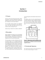
♦ PRECISION INSTRUMENTS FOR TEST AND MEASUREMENT ♦
1413 Precision
Decade Capacitor
User and Service Manual
Copyright © 2003 IET Labs, Inc.
1413 im/May, 2003
IET LABS, INC.
Standards • Decades • Strobes • Sound Level Meters • Bridges
Formerly manufactured by
GenRad
534 Main Street, Westbury, NY 11590
TEL: (516) 334-5959 • (800) 899-8438 • FAX: (516) 334-5988
www.ietlabs.com
Contents
WARRANTY ...........................................................................................iii
WARNING ............................................................................................... v
CAUTION ................................................................................................ v
Section 1
INTRODUCTION .......................................................................... 1
1.1 Purpose .................................................................................. 1
1.2 Description ............................................................................. 1
1.3 Controls and Connectors ....................................................... 1
1.4 Inspection and Unpacking .................................................... 2
Section 2
SPECIFICATIONS ......................................................................... 3
Section 3
OPERATION PROCEDURE ....................................................... 4
3.1 Dimensions ............................................................................ 4
3.2 Mounting ................................................................................ 4
3.3 Connections ........................................................................... 5
3.3.1 Three-Terminal Capacitor ............................................. 5
Section 4
THEORY .......................................................................................... 6
4.1 Circuit Description .................................................................. 6
4.2 Frequency Characteristics ..................................................... 6
Section 5
SERVICE .......................................................................................... 7
5.1 Customer Service .................................................................. 7
5.2 Instrument Return .................................................................. 7
Section 6
MAINTENANCE ............................................................................ 8
6.1 Minimum Performance Standards ......................................... 8
6.1.1 General .......................................................................... 8
6.1.2 Capacitance ................................................................... 8
6.1.3 Terminal Capacitance .................................................... 8
6.1.4 Insulation Resistance ..................................................... 9
6.2 Adjustments ......................................................................... 11
6.3 Knob Removal and Replacement ........................................ 11
Section 7
PARTS LISTS AND DIAGRAMS .............................................. 12
ii
Figures
Figure 1-1. Elementary schematic diagram of the Type 1413 Decade
Capacitor. Connections for all 24 capacitors are similar to those
for the three capacitors shown. .............................................. 1
Figure 1-2. Front panel on the Capacitor.
Six 11-position switches with knobs and dials to set desired value
of capacitance between HIGH and LOW terminals. ............ 2
Figure 1.3 Connection on the rear panel of the 1413. .............................. 2
Figure 3-1. Dimensions of the bench and relay-rack models. .................. 4
Figure 6-1. Top interior view of the Capacitor. ....................................... 10
Figure 7-2. Schematic circuit diagram for the 1413 Precision Decade Capacitor. Switches are shown in zero position. ...................... 12
iii
WARRANTY
We warrant that this product is free from defects in material and workmanship and, when properly used, will
perform in accordance with applicable IET specifications. If within one year after original shipment, it is found
not to meet this standard, it will be repaired or, at the option of IET, replaced at no charge when returned to IET.
Changes in this product not approved by IET or application of voltages or currents greater than those allowed by
the specifications shall void this warranty. IET shall not be liable for any indirect, special, or consequential
damages, even if notice has been given to the possibility of such damages.
THIS WARRANTY IS IN LIEU OF ALL OTHER WARRANTIES, EXPRESSED OR IMPLIED, INCLUDING BUT NOT LIMITED TO, ANY IMPLIED WARRANTY OF MERCHANTIBILITY OR FITNESS FOR
ANY PARTICULAR PURPOSE.
WARNING
OBSERVE ALL SAFETY RULES
WHEN WORKING WITH HIGH VOLTAGES OR LINE VOLTAGES.
Dangerous voltages may be present inside this instrument. Do not open the case
Refer servicing to qulified personnel
HIGH VOLTAGES MAY BE PRESENT AT THE TERMINALS OF THIS INSTRUMENT
WHENEVER HAZARDOUS VOLTAGES (> 45 V) ARE USED, TAKE ALL MEASURES TO
AVOID ACCIDENTAL CONTACT WITH ANY LIVE COMPONENTS.
USE MAXIMUM INSULATION AND MINIMIZE THE USE OF BARE
CONDUCTORS WHEN USING THIS INSTRUMENT.
Use extreme caution when working with bare conductors or bus bars.
WHEN WORKING WITH HIGH VOLTAGES, POST WARNING SIGNS AND
KEEP UNREQUIRED PERSONNEL SAFELY AWAY.
CAUTION
DO NOT APPLY ANY VOLTAGES OR CURRENTS TO THE TERMINALS OF THIS
INSTRUMENT IN EXCESS OF THE MAXIMUM LIMITS INDICATED ON
THE FRONT PANEL OR THE OPERATING GUIDE LABEL.
1413 Series
Section 1
Introduction
1.1 Purpose
The Type 1413 Precision Decade Capacitor is both a
high-quality, wide-range standard and a reliable component for systems. It can be used as a bench model
for versatility, or it can be rack-mounted.
This six-decade capacitor features fine adjustment
over a wide range of capacitance, with excellent accuracy. Any value in the range of 0 to 1.111 11 µF
can be set, with a resolution of 1 pF.
connected together, form the third terminal of the capacitor.
The stability of the 1413 (refer to Specifications) is
such that it should not require readjustment with normal service. However, should it become desirable,
the four lower decades contain trimmer capacitors
that are accessible for this purpose (refer to Section
5.4).
Other units up to 10,000 µF are available; consult IET.
1.2 Description
The six decades have steps of 1, 10, 100, 1000 pF,
and 0.01 and 0.1 F. Air capacitors are used for the
two lower decades, with precision silvered-mica capacitors for the others. Air trimmers are used for trimming the two lowest silvered-mica decades.
The connections to the inner shield and to the case
are shown in Figure 1-1. Low terminal-to-guard and
detector-input capacitances are obtained by dividing
the shielding into two parts. When the two parts are
connected together, the 1413 becomes a well-shielded
three-terminal capacitor with extremely low zero capacitance. The connections are made by means of
BNC connectors on the rear of the cabinet. The inner contacts provide the connections to the capacitors. The outer shells connect to the shields and, when
INTRODUCTION
Figure 1-1. Elementary schematic diagram of the
Type 1413 Decade Capacitor. Connections for all
24 capacitors are similar to those for the three
capacitors shown.
1.3 Controls and Connectors
The controls and connectors on the front and rear of
the 1413 are shown in Figures 1-2 and 1-3.
1
1413 Series
1.4 Inspection and Unpacking
Inspection - If the shipping carton appears damaged,
contact the carrier immediately and request that their
agent be present when the instrument is unpacked. If
the instrument appears to be damaged when unpacked,
have the agent witness its condition, take photos of
the instrument and carton, and retain the carton until
the matter is resolved. Perform an electrical check
immediately to determine if any internal damage has
occurred and file any required claims with the carrier. It may be necessary to return the instrument to
IET
for evaluation, repair estimate and actual repair.
Unpacking - The instrument is wrapped in plastic, and
desiccant may be included if the environmental conditions and destination warrant. Do not unwrap the
instrument until ready to use or install. For bench use,
the bail will raise the front of the instrument if desired. Refer to 2.2 for rack-mounting instructions.
Figure 1-2. Front panel on the Capacitor.
Six 11-position switches with knobs and dials to set desired
value of capacitance between HIGH and LOW terminals.
Access holes for
trimmer Capacitors.
HIGH BNC
connector.
(874 optional)
Cover Plates to protect setting of trimmer Capacitors.
LOW BNC
connector.
(874 optional)
Figure 1-3. Connection on the rear panel of the 1413.
2
INTRODUCTION
1413 Series
Section 2
Specifications
Range: 0 to 1.111 11 F. controlled by six in-linereadout dials.
Accuracy: ±(0.05% + 0.5 pF) at 1 kHz.
Stability: ±(0.01% +0.1 pF) per year.
Temperature coefficient:
<<20 ppm/oC from 10 to 50°C.
Mechanical: Convertible bench/rack cabinet.
Dimensions (w x h x d):
17 x 5.59 x 11.96 in. (432 x 142 x 304 mm);
rack 19 x 5.22 x 10.9 in. (483 x 133 x 505 mm).
Weight: Bench 23 lb (10.5 kg) net, 29 lb (13.5 kg)
shipping; rack 24 lb (11 kg) net, 30 lb (14 kg) shipping.
Zero Capacitance: <0.1 pF.
Voltage Rating: 500 V pk max up to 10 kHz.
Frequency Characteristics: See curves.
Interface: Connections, 2 rear-mounted bnc connectors, adaptable to most other types.
Available: 0480-9703 Rack Adaptor Set to convert
bench models to rack models.
Catalog
Number
1413-9700
1413-9701
0480-9703
SPECIFICATIONS
Description
Bench Model
Rack Model
Rack-Adaptor Set
3
1413 Series
Section 3
Operating Procedure
3.1 Dimensions
The dimensions of both the bench and relay-rack
models of the 1413 are shown in Figure 3-1,
and are also listed in Section 2.
mounting (P/N 1413-9701), it is shipped with RackAdaptor Set P/N 0480-9703, which includes all hardware necessary for mounting the instrument in a standard 19-in. rack or cabinet (refer to Table 3-1). (Order the Rack-Adaptor set alone if a bench model is to
be converted for rack mounting.)
3.2 Mounting
The 1413 may be ordered enclosed in a cabinet for
bench use (P/N 1413-9700). If ordered for rack
Figure 3-1. Dimensions of the bench and relay-rack models.
4
OPERATING PROCEDURE
1413 Series
Fig. 3-2
Ref
C
D
E
Table 3-1
PARTS INCLUDED IN RACK-ADAPTOR SET
P/N 0480-9703
No.
Used
Description
Part No.
2
Rack-Adaptor Assembly (handle)
0480-4903
1
Hardware Set
0480-3080
Includes:
4 Screws, BH 10-32x 5/16"
4 Screws, BH 10-32x9/16",
with nylon cup washers
CAUTION
Remove the cabinet only when converting the instrument from bench to rack mounting or vice versa. Use
extreme care. Do not change the position of the leads
or components, as doing so may alter the calibration.
IET recommends taking accurate spot readings before and after this procedure in order to verify that
the instrument’s electrical characteristics have not
been affected. Cover the unit with a plastic sheet when
working on the cabinet. Clean the inside of the cabinet thoroughly when installation is complete. Replace
the instrument in the cabinet as soon as possible after
the work is completed.
To install the instrument in a rack:
a. Loosen the four captive 10-32 screws in the rear
of the cabinet until the chassis is free; slide the
chassis forward, out of the cabinet.
f. Slide the entire assembly into the relay rack and
install it with the four 9/16-inch screws with
captive nylon cup washers (E). Use two screws
on each side and tighten them by inserting a
screwdriver through the holes in the handles.
To reconvert the instrument for bench use, reverse
the above procedure. Seal the mounting holes if the
working environment warrants such action.
3.3 Connections
CAUTION
The voltage rating of the 1413 is 500 V pk maximum
up to 10 kHz, varying approximately inversely with
frequency above 10 kHz. Do not exceed these values.
b. Match drill the cabinet for proper positioning of
the rack-mount adaptors.
3.3.1 Three-Terminal Capacitor
c. Remove the four feet and the bail from the cabinet if required for clearance.
When the 1413 is used as a three-terminal capacitor,
the outer conductors (shells) of the two bnc connectors must be connected together, to provide complete
shielding.
d. Attach one Rack Adaptor Assembly (G) to each
side of the cabinet using the hardware supplied.
e. Install the instrument in the cabinet and lock it in
place with the four captive screws in the rear
panel that were loosened in step a.
OPERATING PROCEDURE
If binding-post connections are desired, these can be
provided by standard adaptors plugged into the bnc
connectors on the rear of the 1413. Plug the adaptors
into the 1413 with the shield binding posts adjacent to
each other. These shield posts can then be connected
together with a shorting link .
5
1413 Series
Section 4
Theory
4.1 Circuit Description
Each decade consists of four capacitors with values
in the ratio of 1-2-2-5. They are connected in parallel
in different combinations to provide ten equal steps
of capacitance. Individual capacitors that are not used
at a particular setting of the switches are completely
disconnected from the circuit and their high side is
connected to the inner or “guard” shield. The inner
shield and the wiring are arranged to keep the capacitance at the zero setting to a very low value (<
0.1 pF) and to keep the capacitance from HIGH to
case and from HIGH and LOW to the inner shield to
a minimum.
6
An elementary schematic is shown in Figure 1-1 and
the complete schematic circuit diagram is given in
Figure 7-1.
4.2 Frequency Characteristics
Typical variations of capacitance and dissipation factor with frequency are shown in Section 2.
THEORY
1413 Series
Section 5
Service
5.1 Customer Service
5.2 Instrument Return
The IET warranty attests to the quality of materials
and workmanship in our products. For application
assistance or if difficulties occur, our engineers will
assist in any way possible. If you cannot eliminate
the difficulty, please e-mail, FAX, or phone our Service Department, giving full information of the trouble
and of steps taken to remedy it. Be sure to include
the type and serial number of the instrument.
Before returning an instrument to IET for service
please call our Service Department at 800-899-8438
for a Return Material Authorization (RMA). Supply
a Purchase Order Number or Credit Card information to insure expedient processing. Units under warranty will be repaired at no charge. For any questions
on repair costs or shipping instructions, please contact our Service Department at the above number.
To safeguard an instrument during shipment, please
use packaging that is adequate to protect it from damage, (i.e., equivalent to the original packaging) and
mark the box “Delicate Electronic Instrument” and
also with the RMA number. Material should be sent
freight prepaid to:
In the US call:
800-475-1220 or 617-969-0804 for technical support
800-899-8438 or 516-334-5959 for customer service
516-334-5988 for FAX
www.ietlabs.com
IET Labs, Inc.
10 Dedham Street
Newton Highlands, MA 02461
Attention: Service Department
SERVICE
7
1413 Series
Section 6
Maintenance
CAUTION
--The user should not attempt service or repair of
any internal parts or assemblies. Return the instrument to IET of such work is required. See Section
5.2 for shipping instructions.
--Remove the cabinet only when converting the instrument from bench to rack mount or vice versa.
See Section 3.2 for details.
--Store the instrument for short periods in a benign
and dust-free environment (23 ± 10° C and <60%
relative humidity); a laboratory environment is best.
For long-term storage, seal the instrument in plastic-with desiccant if possible--and store at temperatures
between 10° C and 50° C and humidity <80%; Calibrate before use. Since the 1413 is a precision instrument, IET recommends that any storage be in a laboratory environment.
--Clean the external surfaces of the instrument with
a soft, dry cloth that may be moistened with a mild,
general-purpose cleaner; compressed air may also
be used. Keep the 1413 connectors and any mating
connectors clean. Do not open the cabinet, and keep
the rear cover plates in place, in order to keep the
inside of the instrument dust-free.
--Replace the rear cover plates immediately after any
adjustments are completed.
6.1 Minimum Performance Standards
6.1.1 General
6.1.2 Capacitance
The equipment required to check the capacitance
values of the 1413 is listed in Table 6-1.
Connect the UNKNOWN H and L terminals on the
1620 Capacitance Measuring Assembly to the HIGH
and LOW terminals, respectively, on the 1413. Make
the measurements at 1 kHz with the 3-terminal connection. Use appropriate patch cords up to 0.1 µF
and twist them together for measurements above 0.01
µF to reduce the error due to inductance of the cables.
At 0.1 µF and higher, low-resistance connections are
necessary to reduce the dissipation-factor errors
caused by lead resistance. Install bnc-to-binding-post
adaptors on the 1413. Place the instruments so that
the binding posts on the adaptors are close to the bridge
binding posts. Make the connections, with #12 AWG
copper wire, from the bridge H and L terminals to the
1413 HIGH and LOW terminals. Connect a short clip
lead from bridge GND to the shells of both bnc connectors on the 1413.
Maximum dissipation-factor readings are given in the
Specifications.
6.1.3 Terminal Capacitance
Use the 1620 Capacitance Measuring Assembly to
make the various terminal-capacitance measurements.
The connections are given in Table 6-2.
The following tests can be used for incoming inspection, periodic checks, or recalibration of the 1413. The
required equipment is listed in Table 6-1.
8
MAINTENANCE
1413 Series
6.1.4 Insulation Resistance
To measure the insulation resistance, use a GenRad
Type 1863 Megohmmeter or equivalent. Measure the
resistance between the inner conductors of the HIGH
and LOW bnc connectors on the 1413. Connect the
outer shells of both of these connectors to the GUARD
terminal of the Megohmmeter; use alligator clip leads.
Apply 500 Vdc and wait two minutes before measuring the resistance.
Table 6-1
TEST EQUIPMENT
Number
Required
Description
1
Capacitance Measuring Assembly
(includes oscillator, amplifier and bridge)
2
Shielded patch cord/adaptor, GR874-to-BNC
2
Adaptor, bnc-to-binding posts
2
Special shielded cables, bnc
connectors on one end, very
small alligator clips on the other
1
Single banana-plug patch cord,
18 inches or as short as possible
4
Shielded clip leads with small
alligator clips
Recommended
Type*
GR 1620-A
*Or equivalent
MAINTENANCE
9
1413 Series
Table 6-2
Connections for Terminal-Capacitance Measurements
Measurement
HIGH to Case
HIGH to Guard
LOW to Guard
Connection
Bridge L to 1413 HIGH
Bridge H to outer shell of 1413 LOW
Bridge GND to inner conductor of
1413 LOW
Lead Type
Patch cord
Shielded clip lead
Single banana plug
patch cord
Bridge H to shell, and L to inner conductor
of 1413 HIGH
Bridge GND to shell and inner
conductor of 1413 LOW
Shielded clip leads
Bridge L to 1413 LOW
Bridge H to shell of 1413 HIGH
Bridge GND to inner conductor of
1413 HIGH
Patch cord
Shielded clip lead
Single banana plug
patch cord
Patch cord with
alligator clips
Figure 6-1. Top interior view of the Capacitor.
10
MAINTENANCE
1413 Series
6.2 Adjustments
Most of the capacitance in the four highest decades
of the 1413 Decade Capacitor is provided by highquality, precision, sealed, mica capacitors. The capacitance in the two lowest decades (1 pF/step and
10 pF/step) is provided by small adjustable air capacitors (see Figure 6-1). Similar capacitors are provided for trimming the next two decades (100 pF/
step and 1000 pF/step). These capacitors are carefully adjusted in IET’s Calibration Laboratory and
should not need readjustment for several years.
When they are readjusted, a precision three-terminal bridge such as the 1620 Capacitance Measuring
Assembly should be used. Set the bridge for threeterminal measurements and connect the capacitor
to it with BNC-to-874 patch cords.
Remove the two cover plates over the adjustment
holes (Figure 6-2) on the rear of the case. Do not
remove the instrument from its case. Adjust the four
trimmers in the decade (e.g.. those for the 10 pF/
step decade, labelled 10, 20, 40, 50) in order, starting
with the smallest. These numbers refer to the corresponding pF dial settings for that decade. Make the
adjustments with a non-metallic screwdriver through
the hole marked with the corresponding pF value.
MAINTENANCE
Set the switch for that decade to the pF value being
adjusted, with all other switches set to zero. For example, to adjust the 10 pF/step decade, set that dial at
10. and adjust the trimmer marked 10 to give 10 pF
from the HIGH to LOW terminals. Change the dial
setting to 2 and adjust the trimmer marked 20 for 20
pF. Proceed similarly with 40 pF and 50 pF.
In the 1-pF/step decade, the capacitors are set to 1.01,
2.01, 4.01, and 5.01 pF, respectively. All other decades are set to the exact nominal value. When all
values have been set. it is usually desirable to repeat
the adjustment for a slight “touch-up.”
6.3 Knob Removal and Replacement
If it should become necessary to remove a knob from
the front panel to change one that has been damaged,
proceed as follows:
a. Note the setting of the dial on the shaft, so that it
can be replaced property; then loosen the collet
nut in the hub of the dial and slide the dial off of
the shaft.
b. To replace the knob, reverse the above procedure.
11
Rotary switch sections are shown as viewed from
the panel end of the shaft The first digit of the
contact number refers to the section. The section nearest the panel is 1, the next section back
is 2, etc. The next two digits refer to the contact.
Contact 01 is the first position clockwise from a
strut screw (usually the screw above the locating key), and the other contacts are numbered
sequentially (02, 03, 04, etc.), proceeding clockwise around the section. A suffix F or R indicates
that the contact is on the front or rear of the
section, respectively.
Figure 7-2. Schematic circuit diagram for the 1413
Precision Decade Capacitor. Switches are shown
in zero position.
1413 Series
Section 7
PARTS LISTS AND DIAGRAMS
12
PARTS LISTS AND DIAGRAMS
1413 Series
ELECTRICAL PARTS LIST
Ref Des
Description
IET
Part No.
CAPACITORS
Cl
C2
C3
C4
C5
C11
C12
C13
C14
C15
C21
C22
C23
C24
C25
C26
C27
C28
C31
C32
C33
C34
C35
C36
C37
C38
C41
C42
C43
C44
C51
C52
C53
C54
PARTS LISTS AND DIAGRAMS
Air Dielectric, 1.4-5.0 pF
Air Dielectric, 1.4-5.0 pF
Air Dielectric, 1.4-5.0 pF
Air Dielectric, 1.7-8.7 pF
Quartz, Var., 0.6-1.8 pF,
Air Dielectric, 2.7-19.6 pF
Air Dielectric, 2.7-19.6 pF
Air Dielectric, 2.7-19.6 pF
Air Dielectric, 2.7-19.6 pF
Ceramic, 33 pF ±5%, NPO, 500V
96.3 pF ±1 pF
196.0 pF ±1 pF
196.0 pF ±1 pF
496.0 pF ±1.3 pF
Air Dielectric, 1.7-8.7 pF
Air Dielectric, 1.7-8.7 pF
Air Dielectric, 1.7-8.7 pF
Air Dielectric, 1.7-8.7 pF
986.1 pF ±2.1 pF
1989 pF ±5 pF
1989 pF ±5 pF
4989 pF ±5 pF
Air Dielectric, 2.7-19.6 pF
Air Dielectric, 2.7-19.6 pF
Air Dielectric, 2.7-19.6 pF
Air Dielectric, 2.7-19.6 pF
10,000 pF ±2.5 pF
20,000 pF ±5 pF
20,000 pF ±5 pF
.05 µF ±12.5 pF
0.1 µF ±12.5 pF
0.2 µF ±50 pF
0.2 µF ±50 pF
0.5 µF ±125 pF
4380-3500
4380-3500
4380-3500
4380-3600
4910-1180
4380-3700
4380-3700
4380-3700
4380-3700
4410-0335
0505-4030
0505-4031
0505-4031
0505-4032
4380-3600
4380-3600
4380-3600
4380-3600
0505-4033
0505-4034
0505-4034
0505-4035
4380-3700
4380-3700
4380-3700
4380-3700
0505-4036
0505-4037
0505-4037
0505-4038
0505-4039
0505-4040
0505-4040
0505-4041
13
1413 Series
MECHANICAL PARTS LIST
Front View (See Fig 1-2)
Qty
Ref
1
1
1
1
1
2
1
6
6
Description
IET
Part No.
4181-2901
2
Cabinet asm., includes:
Bail*
Gasket (mat’l.)
Foot, left front*
Foot, right front*
Foot, l & r, rear*
*Part of foot/bail kit
Knob/Dial assembly
3
Cap, knob
350019
0051-0006
350020
Rear View (See Fig 1-3)
Qty Ref
14
Description
IET
Part No.
1
1
Connector, bnc, isolated (Std.)
(Other types optional)
31-10/800-2540-03
1
2
Connector, bnc
(Other types optional)
31-221/UG-1094
2
3
Cover Plate
1413-8190
PARTS LISTS AND DIAGRAMS