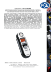
1
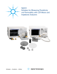
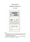
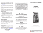
♦ PRECISION INSTRUMENTS FOR TEST AND MEASUREMENT ♦ DE-6000 Portable, Full-Featured LCR Meter User and Service Manual Copyright © 2014 IET Labs, Inc. Visit www.ietlabs.com for manual revision updates DE-6000 im/April 2014 IET LABS, INC. www.ietlabs.com Email: [email protected] TEL: (516) 334-5959 • FAX: (516) 334-5988 ♦ PRECISION INSTRUMENTS FOR TEST AND MEASUREMENT ♦ IET LABS, INC. www.ietlabs.com Email: [email protected] TEL: (516) 334-5959 • FAX: (516) 334-5988 WARRANTY We warrant that this product is free from defects in material and workmanship and, when properly used, will perform in accordance with applicable IET specifications. If within one year after original shipment, it is found not to meet this standard, it will be repaired or, at the option of IET, replaced at no charge when returned to IET. Changes in this product not approved by IET or application of voltages or currents greater than those allowed by the specifications shall void this warranty. IET shall not be liable for any indirect, special, or consequential damages, even if notice has been given to the possibility of such damages. THIS WARRANTY IS IN LIEU OF ALL OTHER WARRANTIES, EXPRESSED OR IMPLIED, INCLUDING BUT NOT LIMITED TO, ANY IMPLIED WARRANTY OF MERCHANTABILITY OR FITNESS FOR ANY PARTICULAR PURPOSE. WARNING OBSERVE ALL SAFETY RULES WHEN WORKING WITH HIGH VOLTAGES OR LINE VOLTAGES. Dangerous voltages may be present inside this instrument. Do not open the case Refer servicing to qualified personnel HIGH VOLTAGES MAY BE PRESENT AT THE TERMINALS OF THIS INSTRUMENT WHENEVER HAZARDOUS VOLTAGES (> 45 V) ARE USED, TAKE ALL MEASURES TO AVOID ACCIDENTAL CONTACT WITH ANY LIVE COMPONENTS. USE MAXIMUM INSULATION AND MINIMIZE THE USE OF BARE CONDUCTORS WHEN USING THIS INSTRUMENT. Use extreme caution when working with bare conductors or bus bars. WHEN WORKING WITH HIGH VOLTAGES, POST WARNING SIGNS AND KEEP UNREQUIRED PERSONNEL SAFELY AWAY. CAUTION DO NOT APPLY ANY VOLTAGES OR CURRENTS TO THE TERMINALS OF THIS INSTRUMENT IN EXCESS OF THE MAXIMUM LIMITS INDICATED ON THE FRONT PANEL OR THE OPERATING GUIDE LABEL. Table of Contents Chapter 1: Introduction ......................................................... 1 1.1. Overview ............................................................................1 1.2. Introduction to measuring principles ..................................2 1.2.1. What is impedance .......................................................... 2 1.2.2. Measuring impedance...................................................... 4 1.3. Equivalent circuit ...............................................................6 1.4. Instrument layout................................................................7 1.5. LCD display layout ..........................................................10 Chapter 2: Operation............................................................ 12 2.1. How to obtain optimum precision ....................................12 2.2. Default settings .................................................................12 2.3. Zeroing the meter .............................................................14 2.4. Attaching DUT’s to the meter ..........................................17 2.5. Primary measurements and functions ...............................19 2.5.1. Measuring inductance, capacitance, and resistance ....... 19 2.5.2. Measuring dissipation, quality, ESR, and phase angle... 22 2.5.3. Sorting components ....................................................... 24 2.5.4. Making relative measurements ...................................... 26 2.6. Additional settings............................................................30 2.6.1. Selecting test frequency ................................................. 30 2.6.2. Making measurements in series and parallel ................. 32 - iii - 2.7. Additional features ...........................................................33 2.7.1. Connecting to a PC ........................................................ 33 2.7.2. Using the backlight ........................................................ 35 2.7.3. Holding a reading on the display ................................... 35 2.8. Replacing Batteries ..........................................................36 Chapter 3: Specifications...................................................... 37 3.1. General specifications ......................................................37 3.2. Accuracy specifications ....................................................39 3.3. Ordering information........................................................42 - iv - Chapter 1: Introduction 1.1. Overview The DE-6000 is a portable, high-performance LCR meter that is full-featured yet cost effective. It measures in true 4-wire Kelvin mode and rivals the capabilities and options of many of its bench counterparts. It measures: Ls/Lp -- Series and parallel inductance Cs/Cp -- Series and parallel capacitance Rs/Rp -- Series and parallel resistance (ac) Rdc/Rp -- Series and parallel resistance (dc) ESR/Rp -- Series and parallel equivalent resistance D -- Dissipation factor Q -- Quality factor Θ -- Phase angle This LCR meter can transfer data to a PC via a standard, fully isolated, optical IR-USB interface. It also features a Sorting mode, allowing users to quickly sort components. DE-6000 has automatic LCR selection. This allows the user to measure the L/C/R components in Auto LCR mode without having to select the type of measurement. -1- To accommodate various test requirements, the DE-6000 offers selectable test frequencies: 100 Hz / 120 Hz / 1 kHz / 10 kHz / 100 kHz. The unit is powered by a standard 9V battery. For additional convenience, it may also use an optional ac adapter (DE-5000-AC). To transfer data to a PC, the unit comes with a built-in IR interface. IET offers an optional Data Transfer Kit (DE-5000-DTK). This kit includes: IR-USB interface adapter, a USB cable, and a CD with software for the PC. 1.2. Introduction to measuring principles 1.2.1. What is impedance Impedance (Z) consists of resistance (real part) and reactance (imaginary part). Series impedance (Zs) can be defined as a combination of series resistance (Rs) and series reactance (Xs). It can be represented mathematically as magnitude |Z|=√(Rs2+Xs2) at a phase angle Θ. -2- Zs = Rs + jXs or |Zs|∠Θ Rs = |Zs| cosΘ Xs = |Zs| sinΘ Xs/Rs = tanΘ Θ = tan-1(Xs/Rs) There are two types of reactance. One is inductive reactance – XL, and the other is capacitive reactance – XC. If Θ > 0, the reactance is inductive. If Θ < 0, the reactance is capacitive. The inductive and capacitive reactances (XL and XC) can be defined as: XL = 2πƒL XC =1÷(2πƒC) Where: L = Inductance C = Capacitance ƒ= signal frequency) -3- 1.2.2. Measuring impedance Impedance can be measured in series or in parallel. In parallel mode, impedance can be represented as reciprocal of admittance (Y). The admittance can be defined as Y = G + jB, where: G = Conductance B = Susceptance Series impedance Parallel admittance Y = 1/Z = 1/Rp + 1/jXp = G+jB Rs = Series resistance Xs = Series reactance Cs = Series capacitance Ls = Series Inductance Rp = Parallel resistance Xp = Parallel reactance Cp = Parallel capacitance Lp = Parallel inductance To understand the ratio of resistance and reactance, it is important to consider two factors: quality factor (Q) and dissipation factor (D). Usually Q is used when measuring inductance and D is used when measuring capacitance. defined as the reciprocal of Q. Q = 1/D = tanΘ Q = Xs/Rs = 2πf Ls/Rs = ½πf CsRs Q = B/G = Rp/|Xp| = Rp/2πf Lp = 2πf CpRp -4- D is Both Rs and Rp are part of the equivalent circuit of capacitors and inductors. When measuring capacitance and inductance, it is best to use the settings as shown in the table below. Capacitance Inductance Value Setting Low Parallel High Series Low Series High Parallel -5- 1.3. Equivalent circuit -6- 1.4. Instrument layout HOLD Sorting Tol 80 120 1 3 6 9 PC Auto Range LCR ESR RP DQO Ls Lp Cs Cp Rs Rp DCR 0 2 °Mk Cal APO kHz Mk 20 40 60 80 POWER LCR AUTO FREQ SORTING PC D /Q /ESR / O SETUP ENTER REL 4 5 7 8 CAL SER /PAL HOLD 12 GUARD 11 10 13 14 Discharge Capacitor Before Test 4-Wire Kelvin Measurement 15 GUARD Front panel Side GUARD provides a shield to reduce noise for device under test (DUT), test leads, and other equipment. -7- 21. TL-21 Alligator –lead test-lead adapter (4-wire joined at alligator clips) 22. TL-22 SMD tweezers, 4-wire (optional) Rear 23. TL-23 Guard Line IR- USB interface (optional) -8- 1. 2. 3. 4. 5. 6. 7. 8. 9. 10. 11. 12. 13. 14. 15. 16. 17. 18. 19. 20. 21. 22. 23. LCD display POWER Turns the instrument on/off. LCR auto mode, Inductance, Capacitance, Resistance and DC LCR AUTO resistance measurement selection FREQ Testing frequency selection Backlight display SORTING Sorting mode control PC ▲ UART output control CAL Open/Short calibration mode D/Q/ESR/Θ D/Q/ ESR/Θ parameters selection Setup menu control SETUP (in sorting mode ) SER/PAL Series and Parallel selection Setup menu control ENTER (in sorting mode ) REL% Relative mode HOLD Data hold Input sockets and Terminals (4-terminal) AC adapter plug Battery cover Tilt-Stand IR Slot IR-USB adapter (optional) TL-21 Alligator-clip test-lead adapter TL-22 SMD tweezers (optional) TL-23 Guard Line -9- 1.5. LCD display layout 1. Sorting 2. Tol 3. kHz 4. 5. PC 6. Range 7. 8. 9. 10. 11. 12. 13. Auto LCR Δ Ls/Lp Cs/Cp Rs/Rp DCR Sorting function is enabled Tolerance indicator in sorting mode : ±0.25%, ±0.5%, ± 1%, ±2%, ±5%, ±10%, ±20%, & +80%-20% Testing frequency indicator: 1kHz,10kHz,100kHz,100Hz & 120Hz PC connection is active Battery capacity indicator Range selection is enabled on setup menu of sorting mode Auto range for L, C or R measurements Checking for L/C/R mode automatically Relative function is enabled Inductance in series or parallel mode is active Capacitance in series or parallel mode is active ac resistance in series or parallel mode is active dc resistance mode is selected - 10 - 14. D/Q/Θ 15. 16. 17. 18. 19. 20. 21. Rp Cal HOLD APO ESR 22. MkΩ ° 23. 24. 25. % 26. 27. 28. 29. MkΩ Dissipation factor, Quality factor or Phase angle is active for L/C measurement mode ac Resistance in parallel mode is active Open/Short calibration mode Data Hold Auto power off mode Series equivalent resistance mode Secondary Display Phase angle Unit for Resistance (Ω, kΩ and MΩ ) – on secondary display Unit for Capacitance ( pF, nF, μF and mF ) – on secondary display Unit for Inductance ( μH, mH and H) – on secondary display The percentage display in relative mode – on secondary display Primary Display Unit for Resistance ( Ω, kΩ and MΩ ) – on primary display Unit for Inductance ( μH, mH and H) – on primary display Unit for Capacitance ( pF, nF, μF and mF ) – on primary display 30. Bar-graph display Special Indication Characters Indicates short calibration Indicates open calibration - 11 - Chapter 2: Operation 2.1. How to obtain optimum precision To access optimum precision for all L, C, and R measurements, especially at the highest and the lowest ranges, zero the instrument before use (pages 16-18). To secure the specified accuracy, connect the device under test (DUT) to the measuring socket, or use either TL-21 (standard accessory) or TL-22 (optional accessory). If you are using test leads other than the ones specified above, use 4-wire leads and avoid using long lead wires to reduce measurement errors. 2.2. Default settings When the power is turned on, the monitor displays all symbols for 2 seconds as shown below. - 12 - When the meter is powered by the battery, it is in an automatic-power-off mode. APO is shown on the display. mode, if the unit is inactive for 5 minutes, it shuts itself off. In this First, the buzzer beeps three times to remind the user, then OFF is displayed on the monitor as shown below while the unit powers down. Note that when the unit is powered via an ac adapter, the automatic-power-off mode is inactive. The default settings for the meter set LCR in auto mode and test frequency at 1 kHz. The battery condition is continuously displayed. the battery capacity is full. means that means that battery power is low and the battery needs to be replaced. The LCR meter uses beeps to indicate whether a particular key has a function in a given mode. single beep. If a functional key is pressed, there is a If a non-functional key is pressed, there is a dual beep. - 13 - 2.3. Zeroing the meter Zeroing the instrument gets better accuracy for impedance measurements. The purpose of this procedure is to reduce the parasitic effect of the test fixture. ZM is the total impedance measured on the device under test (DUT) by a test fixture which has some parasitic impedance. ZM = (Rs + jωLs) + ((Go+jωCo)-1 || ZDUT) ZDUT is the target impedance user wants to measure. It is necessary to use the zeroing process to cancel the effect of Rs+jωLs and Go+jωCo. Ex. Operation for open and short calibration with TL-21 Open Cal. Short Cal. - 14 - Ex. Operation for open and short calibration with .TL-22 Open Cal. Short Cal. To zero the meter, proceed as follows: 1. Make sure the leads are completely disconnected. 2. Press the CAL key for 2 seconds. The monitor should display OPEn as shown below. 3. Pres the CAL key again. The unit should begin a countdown as it performs OPEN calibration. After the countdown is complete, the monitor should say PASS as shown below. If it says fail, the procedure has to be restarted. - 15 - 4. Connect the test leads for form a short circuit. 5. Press the CAL key again. The monitor should display Srt as shown below. 6. Press the CAL key one more time. The unit should begin a countdown as it performs SHORT calibration. After the countdown is complete, the monitor should say PASS as shown below. If it says fail, the procedure has to be restarted. 7. Press the CAL key one more time to exit OPEN/SHORT calibration mode. - 16 - 2.4. Attaching DUT’s to the meter Devices under test (DUT’s) may be connected to the meter as follows: • Insert DIP component leads to the sockets directly. • Attach Alligator-clip test-lead adapter (TL-21) 4-Wire Alligator Test Lead Case (TL-21) Guard line (TL-23) provides a shield for DUT, preventing interference when measuring - 17 - • Attach SMD tweezers (TL-22, optional). Guard line (TL-23) provides a shield for DUT, preventing interference when measuring high-impedance components 4-wire SMD Tweezers (TL-22) - 18 - 2.5. Primary measurements and functions 2.5.1. Measuring inductance, capacitance, and resistance The DE-6000 starts out in Auto LCR mode which can detect the type of impedance and measure it automatically – either inductance (L), capacitance (C), or resistance (R). Dc resistance (DCR) can only be selected manually. The value of impedance is shown in the primary automatically display. selects The and secondary shows the display secondary parameter – either quality factor (Q), dissipation factor (D), or phase angle (Θ). The secondary parameter is based on the L/C/R measurement. When the meter automatically selects impedance automatically, it uses the following procedure: If Q < 0.2, the meter measures resistance. The parameter on sub-display is Θ. If Q 0.2, the meter measures inductance. The parameter on sub-display is Q. If Q -0.2, the meter measures capacitance. The parameter on sub-display is D. If C < 5pF. The parameter on sub-display is Rp. - 19 - Impedance can also be selected manually by pressing the LCR AUTO key. This is what the process would look like: The meter starts out in Auto LCR mode. Press LCR AUTO key. The meter enters Auto L mode. The secondary parameter is Q. Press LCR AUTO key. The meter enters Auto CL mode. The secondary parameter is D. Press LCR AUTO key. - 20 - The meter enters Auto R mode. The secondary parameter is blank. (The meter only displays Θ automatically in Auto LCR mode.) Press LCR AUTO key. The meter enters DCR mode. The secondary parameter is blank. Press LCR AUTO key. The meter returns to Auto LCR mode. - 21 - 2.5.2. Measuring dissipation, quality, ESR, and phase angle The DE-6000 can measure dissipation factor (D), quality factor (Q), equivalent series resistance (ESR), and phase angle (Θ). These readings are shown in the secondary display. To select the appropriate measurement, cycle through the options using the D/Q/ESR/Θ key. Note: that this function is available in Auto L and Auto C modes only. In other modes the D/Q/ESR/Θ key is disabled. Example: In Auto C mode The secondary display shows D. Press D/Q/ESR/Θ key. The secondary display shows Q. Press D/Q/ESR/Θ key. - 22 - The secondary display shows ESR. Press D/Q/ESR/Θ key. The secondary display shows Θ. Press D/Q/ESR/Θ key. The secondary display returns to D. - 23 - 2.5.3. Sorting components The DE-6000 can sort components into PASS/FAIL categories. Components may be sorted based on resistance, capacitance, or inductance. Note: this function is not available in Auto LCR mode. Before using this function, set the meter to either Auto L mode, Auto C mode, or Auto R mode. To enter the Sorting mode, proceed as follows: 1. Zero the meter. Refer to pages 14-16 for details. 2. Press LCR AUTO to cycle through measurement options until the desired impedance type is selected. Note: If you select Auto LCR, the sorting function will not work. 3. Connect one of the items that is going to be measured to the test points. 4. Press SORTING, then press SETUP. Note: If you press the SORTING key while the meter is reading outside limits (OL) or while the reading is less than 200 counts, the Sorting function is disabled. - 24 - 5. To adjust the nominal value, proceed as follows: a. Use ◄ / ► keys to adjust the position of the decimal point as necessary. Press ENTER when finished. b. Use ◄ / ► / ▲ / ▼ keys to adjust the digits as necessary. Press ENTER when finished. 6. To adjust tolerance, use ◄ / ► keys to cycle through tolerance options until the desired tolerance is reached. Press ENTER when finished. Available tolerances are: ±0.25% ±0.5%, ±1%, ±2%, ±5%, ±10%, ±20%, and -20%+80%. The components may now be sorted. The primary display will show either PASS or FAIL as each component is measured. The secondary display will show the value of the measured component, as shown in the sample below. - 25 - To make adjustments to the nominal value or tolerance, press SETUP and repeat steps 5 and 6 above. To exit the Sorting mode, press SORTING. 2.5.4. Making relative measurements The DE-6000 meter can make relative measurements. This option is controlled by the REL% key. When the Relative mode is active, the display shows the Δ symbol. Note: this option is not available in the Auto LCR mode. Nor can it be activated when the parameter being tested is outside of meter limits. The meter uses the following formula to calculate relative measurements: REL% = (DCUR – DREF) / DREF * 100% REL% = Percent difference DCUR = Device currently under test DREF = Device used as a standard - 26 - To access the Relative mode proceed as follows: 1. Zero the meter. See pages 14-16 for details. 2. Select the parameter to be tested. L, C, R, or DCR 3. Attach the chosen standard to the test points. 4. Press the REL% key. The meter should now display the Δ symbol. 5. Remove the standard and attach a DUT to the test points. The primary display should show the value of the DUT and the secondary display should show the % difference from the standard. 6. Repeat Step 5 for each DUT. Note: The range for the % difference is -99.9% to 99.9%. If the DUT falls outside that range, the secondary display will show OL. 7. To exit, press and hold the REL% key for 2 seconds. - 27 - Example: In Capacitance mode Display shows the measurement reading. Ex. 669.3 nF Press REL% key Δ appears on the screen The reading on the display is stored as reference value. 0.0% is shown on the secondary display since the measured value and the reference are the same at this point. Remove the standard and attach a different device The new reading is shown on the primary display. The % difference is shown on the secondary display. Remove the current DUT device under test and insert another. - 28 - The new reading is shown on the primary display. The % difference is shown on the secondary display. Press REL% key again Δ flashes on the screen, and the reference value shows on primary display. - 29 - 2.6. Additional settings 2.6.1. Selecting test frequency The DE-6000 meter can test at the following frequencies: 100 Hz, 120 Hz, 1 kHz, 10 kHz, and 100 kHz. The default frequency setting is 1 kHz. To cycle through the available frequencies, pres the FREQ key. The default test frequency is 1kHz. Press FREQ key. The testing frequency is now 10kHz. Press FREQ key. The test frequency is now 100kHz. Press FREQ key. - 30 - The test frequency is now 100Hz. Press FREQ key. The test frequency is now 120Hz. Press FREQ key. The test frequency returns to 1 kHz. Note: test frequency affects the accuracy of the reading. See accuracy charts on pages 35-36. The LCR impedance scale ranges are based on the test frequency. - 31 - 2.6.2. Making measurements in series and parallel The DE-6000 meter can make measurements in series or parallel. To select the appropriate option, press the SER/PAL key. Note: this function is available in Auto L, Auto C, and Auto R modes only. In other modes the SER/PAL key is disabled. Example: In Auto C mode The default setting for capacitance is in series mode. The display shows Cs. Press SER/PAL key. The meter switches to parallel mode. The display shows Cp. Press SER/PAL key. The meter returns to series mode. The display shows Cs. - 32 - If the user does not select series or parallel modes manually, the meter will do so automatically. The meter automatically selects parallel mode if impedance is more than 100 kΩ, and series mode if impedance is less than 100 kΩ. 2.7. Additional features 2.7.1. Connecting to a PC The IR slot on the rear of the IR-USB adapter USB socket meter makes it possible to connect to a PC for remote operation and data storage. If you have the optional Data Transfer Kit (DE-5000-DTK), you may connect to a PC as follows: Snap on IR-USB adapter and connect to a PC via a USB cable. Display shows the measurement reading. Press PC ▲ key. - 33 - PC communication is active. PC appears on the display. Press PC ▲ key. PC disappears from the display, and the PC communication is inactive. - 34 - 2.7.2. Using the backlight To use the back light, press the key. To turn it off, press key again. Note that the backlight is disabled automatically after the meter is inactive for 60 seconds. 2.7.3. Holding a reading on the display Normally, the reading of any given DUT disappears as soon as the device is disconnected from the test points. To hold the reading, press the HOLD button. Note: while in the Hold mode, only the operate. To exit this mode, press the HOLD button again. - 35 - will 2.8. Replacing Batteries The DE-6000 is powered by a single, standard, 9 V, alkaline battery. When the battery is at full power, the display shows . When the battery power is running out, the display shows . Caution: To maintain the meter within specifications, replace the battery as . soon as the display shows To replace batteries, proceed as follows: 1. Turn the meter off and remove any test leads and external adapters. 2. Remove the tilt-stand. 3. Remove the four screws holding the battery cover and take the cover off. 4. Replace the battery with a standard 9 V alkaline battery. Caution: observe correct polarity. 5. Replace the cover and the screws removed in Step 3. - 36 - Chapter 3: Specifications 3.1. General specifications Parameters measured: Ls / Lp / Cs / Cp / Rs / Rp / DCR with D/Q/Θ/ESR measurement Automatic L-C-R selection Selectable test model: Series or Parallel Display: Backlit 20,000/2,000 count Input connection: 4-Wire spring-loaded sockets and biding post jacks Accepts normal or shrouded banana plugs Automated LCR ranges: L: 20.000 μH -- 2000 H C: 200.00 pF -- 20.00 mF R: 20.000 Ω -- 200.0 MΩ DCR: 200.00 Ω -- 200.0 MΩ Selectable test frequencies: 100 Hz / 120 Hz / 1 kHz / 10 kHz / 100 kHz Measurement rate: 1.2/second nominal - 37 - Response time: Approx. 1 second/DUT Available tolerances for sorting function: ±0.25% ±5% ±0.5% ±10% ±1% ±20% ±2% -20/+80% Temperature coefficient: [0.15 x (specified accuracy)]/°C 0-18°C, 28-50°C Test signal level: 0.5 Vrms Typical Environmental: Operating temperature: 0°C to 50°C; <70% RH Storage temperature: -20°C to 60°C; <80% RH Battery: Uses a single, standard 9 V battery Display includes battery level indicator Mechanical: Dimensions: 18.8 cm H x 9.5 cm W, 5.3 mm D (7.4" x 3.75" x 2") Weight: 350 g (0.75 lb) - 38 - 3.2. Accuracy specifications Accuracy is specified at 23°C ± 5°C, <75% RH. All accuracy is specified as ±[(% of reading) + (value of least significant digit)]. For most precise measurements, the meter has to be zeroed first. Resistance: Range 20.000 Ω 200.00 Ω 2.0000 kΩ 20.000 kΩ 200.00 kΩ 2.0000 MΩ 2.000MΩ 20.000 MΩ 20.00 MΩ 200.0 MΩ Resolution 0.001 Ω 0.01 Ω 0.0001 kΩ 0.001 kΩ 0.01 kΩ 0.0001 MΩ 0.001 MΩ 0.001 MΩ 0.01 MΩ 0.1 MΩ 100/120Hz ─ 1.0%+3 0.3%+2 0.3%+2 0.5%+2 1.0%+3 ─ 2.0%+3 ─ 2.0%+3 1kHz 1.0%+3 0.2%+2 0.2%+2 0.2%+2 0.5%+2 1.0%+3 ─ 2.0%+3 ─ 2.0%+3 10kHz 1.0%+3 0.3%+2 0.3%+2 0.3%+2 0.5%+2 1.0%+3 ─ ─ 2.0%+3 ─ 100kHz 2.0%+3 0.6%+3 0.6%+3 0.6%+3 1.0%+3 ─ 2.0%+3 ─ ─ ─ Resolution 0.01 pF 0.1 pF 0.001 nF 0.01 nF 0.1 nF 0.001 μF 100/120Hz ─ ─ 2.0%+3 0.3%+2 0.3%+2 0.3%+2 1kHz ─ 2.0%+3 0.2%+2 0.2%+2 0.2%+2 0.6%+2 10kHz 1.2%+5 0.3%+2 0.3%+2 0.3%+2 0.6%+2 1.2%+5 100kHz 2.0%+5 0.6%+3 0.6%+3 0.6%+3 2.0%+5 ─ 3.0%+5 (10μF max.) ─ Capacitance: Range 200.00 pF 2000.0 pF 20.000 nF 200.00 nF 2000.0 nF 20.000 μF 20.00 μF 0.01 μF ─ ─ ─ 200.00 μF 0.01 μF 0.6%+2 1.0%+3 200.0 μF 0.1 μF ─ ─ 2000.0 μF 2000 μF 20.00 mF 0.1 μF 1 μF 0.01 mF 1.0%+3 ─ 1.2%+3 ─ 1.2%+3 ─ ─ 3.0%+5 (100μF max.) ─ ─ ─ *If reading <2000, unit on display is pF - 39 - ─ ─ ─ ─ Inductance: Range 20.000 μH 200.00 μH 2000.0 μH 20.000 mH 200.00 mH 2000.0 mH 20.000 H 200.0 H 2.000 kH Resolution 0.001 μH 0.01 μH 0.1 μH 0.001 mH 0.01 mH 0.1 mH 0.001 H 0.1 H 0.001 kH 100/120Hz ─ ─ ─ 1.2%+5 0.3%+2 0.3%+2 0.3%+2 0.6%+3 1.2%+5 1kHz ─ ─ 2.0%+5 1.0%+5 0.6%+3 0.3%+2 0.6%+3 1.2%+5 ─ 10kHz ─ 1.2%+5 0.6%+3 0.3%+2 0.3%+2 0.6%+3 1.2%+5 ─ ─ 100kHz 2.5%+5 0.6%+3 0.6%+3 0.6%+3 1.2%+5 ─ ─ ─ ─ 100kHz 2.5%+5 1.2%+5 0.6%+3 2.5%+5 2.5%+5 (2 MΩ max.) ─ *If reading <2000, unit on display is μH DCR: Range 200.00 Ω 2.0000 kΩ 20.000 kΩ 200.00 kΩ 2.0000 MΩ 20.000 MΩ 200.0 MΩ Resolution 0.01 Ω 0.0001 kΩ 0.001 kΩ 0.01 kΩ 0.0001 MΩ 0.001 MΩ 0.1 MΩ Accuracy 1.0%+3 0.2%+2 0.2%+2 0.5%+2 1.0%+3 2.0%+3 2.0%+3 Accuracy v.s. Resistance (ZDUT): 0.1-1 Ω 1-10 Ω 10-100 kΩ 100 k-1 MΩ DCR 1.2%+5 0.6%+3 0.3%+2 0.6%+3 100/120Hz 1.2%+5 0.6%+3 0.3%+2 0.6%+3 1kHz 1.2%+5 0.6%+3 0.3%+2 0.6%+3 10kHz 1.2%+5 0.6%+3 0.3%+2 0.6%+3 1 M-20 MΩ 1.2%+5 1.2%+5 1.2%+5 2.5%+5 >20 MΩ 2.5%+5 2.5%+5 2.5%+5 ─ - 40 - Adjustment to accuracy (Z) based on dissipation (D) reading: D > 0.1: Z * √(1+D2) In capacitance mode, D ≤ 0.1: ZC = 1÷(2πƒC) In inductance mode, D ≤ 0.1: ZL = 2πƒL Secondary Parameters Accuracy: AZ = impedance (Z) accuracy Definition: Q = 1/D & Rp = ESR * (1+1/D2) D value accuracy: DZ = ± AZ *(1+D) ESR accuracy: RZ= ± ZM * AZ (Ω) ie., ZM = impedance calculated by 1÷(2πƒC) or 2πƒL Phase angle Θ accuracy: ΘZ= ±(180/π)*AZ (deg) - 41 - 3.3. Ordering information DE-6000 Standard Package: LCR meter DE-6000-LCR Carrying case DE-5000-CS Alligator-clip test-lead adapter TL-21 (4-wire joined at the alligator clips) Guard lead TL-23 Standard 9 V battery DE-5000-9V Instruction manual DE-6000-IM Optional Accessories: AC adapter DE-5000-AC SMD tweezers (4-wire) TL-22 Data transfer kit DE-5000-DTK • IR to USB Interface Adapter • USB cable • CD with software for PC - 42 - ♦ PRECISION INSTRUMENTS FOR TEST AND MEASUREMENT ♦ IET LABS, INC. www.ietlabs.com Email: [email protected] TEL: (516) 334-5959 • FAX: (516) 334-5988 IET LABS, INC. www.ietlabs.com Email: [email protected] TEL: (516) 334-5959 • FAX: (516) 334-5988