1
PIONEEFI
SOLID STATE
AM/FM STEREORECEIVER
Model
s)Ges|o
CAUTION
v
Beforeconnectingthe line cord to the wall socket,carefullyreadand
below,to assurethe safetyof your
follow the instructionsdescribed
unit.
. This rsceiveris setfor 24OVoperationwhenshipped.lf this unit
is us€d in a different linevoltagearsa,readand follow "LINE
AND FUSE"on page1. Besurethatthe
VoLTAGESELECTION
your
unit agreeswith tho line voltagsin
lin€ voltagessttingon
your areaand that the fuse installedin your unit is a properone.
AND SERVICEMANUAL
OPERATING
INSTALLATION,
PARTSLIST,CIRCUITDIAGRAMS,TROUBLE'
Including
SHOOTINGAND MOUNTINGTEMPLATE.
(FVW)
J
PIONEERELf,CTRtrNIE EtrRPtrRATItril
IrJIONEEFI
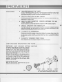
HIGH.PERFORMANCE
FM TUNER
FEATURES
An FET {field-effect transistor) is used in th€ radiofrequency amplifier to attain a high
sensitivhy and selectivity. Funher, four lcs (integrated circuits) are us€d for th€
intermediatefrequency amplifier to eliminate interferenceand noise.
FM MPX CIRCUIT
BUILT.INEXCELLENT
This srwitchingcirdit having exc€llent separationand frequency responseis built in for
reproduction of reality music.
FERRITEANTENNA FOR AIII
BUILT-INHIGHLY-SENSITIVE
RADIORECEPTION
The ferrite antennaprovideshigh-sensitivityreceptionof AM broadcastprograms.
.
w
SPECIALCIRCUITRYFOR VERSATILITY
transistors,
two seGof loudspeakor
terminals
The highoutput givenby strictly selected
and phonoterminals,and the provisionfor usinga microphonemakeModelSX-990
usea well 6 the family use.
suitablefor the professional
A VARIETYOF ACCESSORIES
Accessoriesinclude the program lamps that indicate the program being played, the
tuning metersvertically arrangedfor facilitating selection of an FM broadcastprogram,
the loudspeakerselectorswitct, tape monitor switch, etc., all for enjoyableuse of Model
sx-990.
ELEGANTLY
FRONTPANEL
DESIGNED
Narvly designedknob6are uniquely arrang€don the silver tone panel.
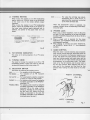
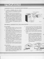
LINE VOLTAGESELECTIONAND FUS
SWITCHING LINE VOLTAGE SETTING AND FUSE
In orderto removethe fuse,tum the fusecaplocated
on the line voltageselectorswitch in the direction
indicatedby an arJow.Then removethe fuse plug
from the unit. Put the fuse plug back so that the
properline voltagemarkingcan be seenthroughthe
cut in the edgeof the plug.
Wheneverthe set positionof the selectors itch is
changed,
checkthe ratingof the fuse.A l-amperefuse
is to be usedfor either 220V or 24OVoperationand
2-ampere
fuse for any of 110V, 117V, or 130V
operation.lf the rating of the fuse is proper,install
the fusein the fusecaD.
v
R E P L A C I N GO F F U S E
When the fuse is blown, removethe fuse cap and
replacethe fus€with a nevvone.
Fis.1
@
cott{
FUSEPLUG
Take off the fuse cap by turning it with a coin,
etc. in the directionindicatedby the arrow mark,
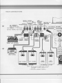
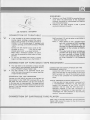
REARCONNECTIONS
TAPE
RECORDING
RECORDPLAYER GND
I
TERMINAL
TAPE REC / P.B.
CONNECTOR
TAPE
CRYSTAL /CERAMIC
MAGNETIC
ALL TERMINALS
ARE INTERNALLY
*'"9*O
AS FOLLoWS:|
wrREo
(DIN TYPE)
LJJL4]EF
"!T]!"
PHONO I PHONO2
ry q! ry
TAPE
TAPE
MONITOR R E C / P . S .
x;l*;;;;;:::i:11$
EE E
fo)
ro)l
LINE VOLTAG
SELECTOR AI
SPEAKEROUTPUT
FTERMINALS'l
(4n-l6a) g
TURNTABLE
CENTER
CHANNEL
220V
2A
t30v
(MM) CARTRIDGE
I tov
NOTE : tf the
( " D l N " t y p e )i s
I
CONNECTOR ,
and MONITOR
TAPE PLAYER
@
LEFT CHANNEL
A-SPEAKER SYSTEM
RIGHT
CHANNEL
@
CHANNEL
B-SPEAKER SYSTEM
NOTE: l. Wh€n only on€ s€t of sP€aker syst€m is connected
to th€ Sx-99O. The spesk€r imPedancemav be 4
to 16 ohms.
2. Do not short the SPEAKER TERMINALS.
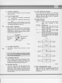
STEREOSYSTEM
FM ANTENNA
The SX-990 is a generafpurpce stereo amplifier.
Connect to it the loudspeoker systems (two or four),
turntablo, tape recorder, etc., which are separately
6vailable.
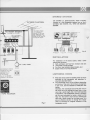
lI the indoor antenna
js not adequate for
reception of FM Programs. seParat€ly establish an antenna in the
outside ol th€ house for
receiving FM sig als
FM ANTENNA
TERMINALS
230 VA
Fig.3
INSTALLATION
For installation of the stereo system, select a place
rneetingthe follo\,ving:
.
Well ventilated. and free from moisture and dust
.
Unexposedto direct slnlight
a Far from heat radiators(spaceheaters.etc')
.
Stablewithout incurring vibrations
LINE CORD
ecordlplaybackconnector
rrovided on your tape
A P E R E C/ P , B .
LISTENINGROOM
.erDinals to the rsceiver
.
.
(TAPE RECOROER)
Fis.2
When the stereosystemis installed,listento music
according to the connection and operation instructionsdesc'riH below.
The reproducedsound isvery diffurent depending
on the size of the room, the furniture anangement
in the room, and the materialsof walls,floor and
ceiling.
Generally,the reproduc€dsound fills the room if
the room has a low ceiling and hard floor, or the
room has a small length and a hard wall opposing
This undesirableacoustlg condition
loudspeakers.
can be much alleviat€dby laying a carpet on the
floor for the former room and by covering the
wall with a thick olrtain for the latter room. lt is
also an effective solution to dlange the arrange
ment of fumitur6 for irregular reflection of ttle
loudspeakersound.
IPIONEETT
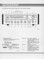
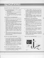
CONTROLSAND SWITCHESON THE FRONT PANEL
PROGRAM
3 rruotcnroRLAMPS
FM _E6 e0 s2 s4 .g!jgj0g_-10:__I0j_!0j_!0!_.MHz
iaö-i6t-xrokrz
l3 14 15 t6
Fig.4
l.
SPEAKERSSWITCH
A combination of the Doweron/off switch and th€
loudspeakersystemselectorswitch.
NNss
Kß:wslf o,NNKK
ss"G@mffKr:
+
sexn,s-orr_lr+e_:;1
SPEAKEFIS
Fi$ 5
POWEROFF:.....The
equipment
isdeenergized.
The power supplied from the
S1I/ITCHED
AC outlet (36) is discontinuedsimultaneously.
A: ...--"..-".'..-..Soundis reproduced
from the loudspeaker system connected to the
(31
SPEAKEROUTPUTA terminals
and321.
stopsounding.
SPKR OFF: .......Loudspeakers
This positionis selectedwhenusinga
stereoheadphone.
B: .......-....-.'...'...The
loudspeaker
systemconnectdto
the SPEAKEROUTPUTB terminals
(33 and34) is put in operation.
systems
connected
to
A + B: .. ......"--.Theloudspeaker
SPEAKEROUTPUTA and B terminalsareput in operation,
2. TUNINGMETERS
When tuning the receiver to an AM broadc6tirE
station, adjust the TUNING knob (4) so the pointer
of the lower one of the meters deflects largely
rightward.
When tuning the receiver to an FM broadcasting
station, adiust the TUNING knob so the pointer of
the lower meter deflects largely rightward and, in
addition, the pointer of the upper meter is at the
center,
Tuning to AM Rädio Station
Tuning to FM Radio Station
tw-t""*
Fis.6
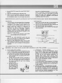
AUX: .....-'......'For usingthe cartridge
tape player,
reproducingthe TV audiooutput, or
operatingotherequipmentconnectd
to the AUX terminals(20).
When the SELECTORsl,vitchis operated.the
programindicatorlampcorresponding
to the selected sourcelighß.
6.
PHONES JACK
Whenusinga stereoheadphone,
insertits plug into
this iack. For the headphone
to be usedwith Model
ModelSE-20,
SX-990,PIONEER's
SE-30or SE-50is
recommended.
When a longer cord is required for the stereo
headphone.use PIONEER'sModelJB-23 extension
cord separatelyavailable.
When desiring to connect two stereo headphonet
use PIONEER'sModel JB-22 "Y" cord separately
available.
7. BASSCONTROL
3. FM STEREOINDICATOR
This lamp is lit during reception of an FM stereo
program.
4. TUNING KNOB
The knob for tuning the receiverto an AM or FM
stätion.Adiust the knob for the best
broadcasting
tuningwhileobs€rving
the tuningmeters(2).
5. SELECTOR SWITCH
Thes,witchfor selecting
the programsource.
AM: .......'.........Forreception
of an AM program.
FM MONO:...,. For rec€ptionof an FM monaural
program,
FM AUTO: ...." For automaticallyselectiv€reception
of stereoor monauralFM Program.
PHONO1............
For playinga diskrecordby usingthe
turnbble connectedto the PHONO1
(17),
terminals
PHONO2/MlC: For playinga disk recordby usingthe
turntableconnectedto the PHONO2
terminals(18) or for usinga micp
phoneby insertingits cord plug into
the MIC iack (16). (Whenthe micro
phone is connectedto the iack, the
turntableconnectedto the PHONO2
terminalscannotbeused.)
When this knob is turned clockwise,bassis boosted;
when tumed counterclockwise.attenuated.Whh the
knob set to the center,the frequency responsecurve
is flat. The center and outer knob6 of this double
knob are friction-coupled with each other. and the
tone of both left and right channelscan be adjusted
simultaneouslyby tuming either knob. The center
knob is for the left channel.and the outer knob is
for the right channel. When adjusting the tone of
onlv one of the channels,turn the knob for that
channel while holding the other knob by the other
hand.
RIGHT CHANNEL
( c H. R )
LEFT CHANNEL
( c H. L )
Fis.7
OI
14. TAPE MONITOR SWITCH
8. TREBLE CONTROL
Use of this knob is similar to that of the BASS
control knob (7).
9, FILTER SWITCHES
low-frequency
LOW: A svtitchfor suppressing
or hum.
noise
HIGH: A su?itch for zuppressing high-frequency
noise.
These s,witchesare of the pushbutton type. When
the button is pressedonce, the switch tums on. and
when pressedonce again,it turns off,
v
10. BALANCE CONTROL
This knob is used for adjusting the stereophonic
balance.When the volume of the right channel
loudspeaker is smaller, turn the knob clockwise
toward RIGHT;when left channelvolumeis smaller,
counterclockwisetoward LEFT
BALANCE
wh€nthe volume*.)"jltf
teft channet
toudspeak6r
it
lk-+:\)
smatt€r
VrZ
LEFT-
whenthe volumeo{
chsnnel
N right
is
loudsPeaker
smaller
Turn on this switch for listening to or monitoring
only the signalreproducd by a tape deck (or tape
recorder). When not using the tape deck (or tape
recorder). keep this switch turned off. Otherwise,
loudsoeakenwill not sound.
15.MODESWITCH
Functionsas follows:
REV....... Stereo, with lefi and right channel
input signals exchanged for each
other.
STEREO..' Normalstereo
L.....'...'-"' Monaural play with only the left
channel input signal fed to both
channelloudsDeakers.
R.............. Monaural play with only the right
channel input signal fed to both
channelloudsPeakers.
L + R ........ Monauralplay with both leftand right
channel input signalsmixed together
and reoroduced from both channel
lou&Deakers.
f----
FTIGHT
R*
--__l
l-..'------T-----_.-/-_--'---']
'r1.","
---H\---f
Fig.8
**T]:"
ll
11. VOLUME CONTROL
I
The volume increaseswhen the knob is turned
clockwise,
t
LEFrv ----t----------I^DUTIIIOUTPUT
L-R'GHro
I
*;--___]
rlr-r
---.t
L.-."'."'-
12, 13 and 14 are pushbuttonswitches.Switches
once;
are depressed
turn on when the pushbuttons
again.
turn off whendepressed
SWITCH
12. LOUDNESS
With this switch turned on when the sound volume
is low, insufficienciesof bass and treble are compensatd for. When the sound volume is high, it is
recommendd to keepthis s,witchturned off.
13.MUTINGSWITCH
Turning on this switch, the noise generatedwhen
tuning the receiver to an FM station can be
eliminated. lf l\4odelSX-990 is used where the FM
field strength is low, keep this str/itch turned off
since the program sound is also suppressedwith the
switchtumed dn.
r
.--;;--_--l
't:1.,,"
-+--------t-F
-LEFro---t------------
!LE;r---.1
"",."?'i.
JACK
16.MIC {MICROPHONE}
Fis.9
When a microphone is connecGd to this iack, the
signal fed from the turntable connected to the
PHONO 2 terminals (18) on the rear panel is
d isconnected,
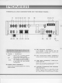
ITJTONEEII
TERMINALSAND CONNECTORS
ON THE REARPANEL:
17 18t9 202122 23
2829 30 3132 3334
252627
35 36 37
3B
F i s .1 0
The upper onesof the terminals17, jA,20,21,22,
28 and 29 are for the left channelrespectively;the
loweronet for the right channel.
1 9 . G N D ( G R O U N DT) E R M I N A L1
lf the turntable or other equipment used with
[/odel SX-990 is provided with a ground wire,
connectthe wire to this terminal.
17. PHONO 1 TERMINALS
MAG: .,.......Connect here a turntable equipped
with a moving magentcartridge.
CER: .,,....,..Connect here a turntable equipped
with a ceramicor crystal cartridge.
NOTE:
Two turntablecannot be connected
to the MAG and CER terminals
simultaneously.
18. PHONO2 MAG TERMINALS
Connect here a turntable equipped with a moving
magnetcartridge.
2 0 .A U X . ( A U X I L I A R Y )I N P U TT E R M I N A L S
Connectherethe output of a cartridgetapeplayer.
2 1 .T A P E M O N T E R M I N A L S( T A P EP L A Y .
B A C KI N P U T S )
Connectthe iine output or monitor output of tape
deck (or tape recorder)to thesetermanals.
22. T APERECTERMINALS(TAPE RECORDING OUTPUTS)
Connect the line input of a tape deck (or tape
recorder).Signalis alwayssuppliedto theseterminals while SX-990 is working; however,the signal
OI
cannot be controlledwith the VOLUME (11),
BALANCE(10),TREBLE(8) or BASS(7) control
on the fmnt Danel.
w
23. TAPE RECiPB CONNECTOR
(DI N TYPE)
lf the tapedeck (or tape recorder)to be usedwith
Modet SX-990is providedwith a record/playback
connectorof the DIN type, the tapedeck (or tape
recorder)canbeconnected
to ModelSX-990for both
recordingand playback(and monitor) by simply
connecting
the DIN cable.
Whenthis cable is used,connections
to terminals
(21t.andl22l areunnecessary.
The detail of connectionis shown on pagelO.
Connection
of tapedeck(or taperecorder),,.
24. AM FERRITEANTENNA
Wherethe field strength is high, adjust the direction
of this ferrite antenna for good reception, without
using an external antenna. lf good reception cannot
be obtained, see page g. "Antenna Cmnection and
Grounding".
25, AM ANTENNA INPUT TERMINAL
Connect a lead wire or outdoor AM antennato this
terminal if the ferrite antenna (24) cannot get
good reception.
26.GND {GROUND)
TERMTNAL
2
Connect
a groundwireto thisterminal.
27. FM ANTENNA INPUT TERMINALS
Connectan FM antennato theseterminals.
NOTE:
For the details of AM antenna, FM
antennaand grounding, see"Antenna
connection and grounding" on pageg,
28. PRE-AMP OUTPUT TERMINALS
The outpr.rtof preamplifier stage,which is the signal
having passed the tone control circuit is always
suppliedto theseterminals.
INPUTTERMINALS
29.MAIN-AMP
Theseare input termirElsof the power amplifier
stageof ModelSX-990.
The PRE-AMP OUTPUT(28) and MAIN-AMP
INPUT (291terminalsare connected
to eachother
with the iumperplugs.With theseplugsremoved,
the preamplifier and power amplifier stage of
Model SX-990can be usedapart. This systemis
conveniertfor compocings multi.amplitiersystsm
andotherpurposes.
30.CENTERCHANNELOUTPUTTERMINAL
The signals of left and right channels are mixed
together and supplied to this terminal at all times.
The terminal may be used for composing a 3-D
rystem or connectinga center-channelamplifier.
31. & 32. SPEAKEROUTPUTA TERM|.
NALS
Model SX-990 is designedto permit connection of
twö setsof stereoloudspeakersystems.
Connect the first set of loudspeakersystem (system
A) to these terminals; the right channelto terminal
(31) and the left channelto terminal(32).
33. & 34, SPEAKEROUTPUTB TERMI.
NALS
Connectthe right channelloudspeaker
of the second
loudspeaker
system(systemB) to terminal(33)and
the left channel loudspeakerof this systemto
terminal(34).
For connectionof loudspnakrsto the SPEAKER
OUTPUTA and B terminals,the plugssuppliedas
accessories
must be us€d.Follow the instructions
under"ConrEctionof loudspeaker
system"on page
9, for the conect useof the plugs.
35. LINE VOLTAGE SELECTOR AND
FUSEHOLDER
This selector is used for setting the SX-990 to suit
the line voltägeto be supplied. lt alsoserves6 a fuse
holder.
For the selectorsetting and fuse replacementproce.
dures,referto the article"LINE VOLTAGE SELEG
TION AND FUSE". (Page1)
AUXILIARYAC OUTLET
36. SWITCHED
A power of 230 VA can be supplied to a tumtable
or other eqüipment from ülis outlet. The power
supply is turned on and off correspondingto thc
turningFon and off operations of the SPEAKERS
sl ritch (1) on the front panol.
37. UNSWITCHEDAUXILIARY AC OUT.
LET
Thepoweroutlet alsohavinga capacityof 230 VA
total. The power from this outlet is supplied
regardlesof the operationof the SPEAKERS
srt/itch
(11.
38. AC POWERCORD
After all the extgrnal equipment is connected to
Model SX-990, connect this cord to a mmmercial
pow€r outlet havinga sufficient capacity.
ITJIONEETT
SYSTEM
OF LOUDSPEAKER
CONNECTION
a
To connect a loudspeaker,take out a speaker
connector plug from the accessoriesbag, and connect it to the leadsof the loudspeakeras illustrated
SPEAKER TERMINALS
tn |:to- | t.
Be sureto connectthem for the correct polarity.
When the plugs have been connected to loudspeakers,connect the plug of the right channel
to the SPEAKEROUTPUT A terminal
loudspeaker
(3?) and that of the left channelloudspeaker
to the
SPEAKER OUTPUTA terminal132).(See Fis. 2.)
When using an additional loudspeakersystem,
connect the speakerconnector plugs to the loudabove,and connectthe plug of
speakers
as described
the right channel loudspeakerto the SPEAKER
OUTPUT B terminal (33) and that of the left
to the SPEAKEROUTPUT B
channelloudsDeaker
terminal{34).
(+)
POSTTIvE
NEGATIVE (_)
\.,
F i s .1 1
AND GROUNDING
ANTENNACONNECTION
FM ANTENNA
.
o
When using l\4odelSX-990 at a placeof low field
strengrthor distant from the station, selectthe most
suitableFl\4antennaasfollows:
T-type indoorantennawhen using
Usethe accessory
Model SX-990 within a wooden building near the
Fl\4 radio station. Connect the free and of the
vertical section of the antenna to the F l\4 antenna
terminals(27) asshownin Fig.l2.
Expandthe horizontalsectionof the antenna,and
determine its direction for good receptionwhile
actually receivinga broadcastprogram. Fix the
horizontalsection on a wall or other olace in the
determineddirection. For the operatingprocedure,
'l
see"Reception of Flvl broadcast"on page 1,
When using Model SX-990at a long distancefrom
the station,or within a building,installan outdoor
FM antenna.and connect it to the Fl\4 antenna
t e r m i n a l (s2 7 )a si n F i g .1 3 .
of 3 to
The Fl\4antennais variousin type, consisting
7 elements.Selectthe optimum antennaby consulting a nearbyradio,TV or hi-fi equipmentsalesstore.
AM ANTENNA
When using Model SX-990 near the broadcasting
station or insidea wooden building,connectionof
Adiust the
an externalAM antennais unnecessary.
directionof the AM ferrite antenna(24) locatedon
the rear panel for the best radio receptionwhile
actually listeningto broadcasts,referringto "Re
ceptionof AM broadcast"on page11.
lf good radio reception cannot be attained with the
AlVl ferrite antenna {24), use the accessoryAM lead
wire antenna.Connectone end oi the antennato the
AM antennaterminal (25), and expand the wire
a l o n ga w a l lo f t h e r o o m . ( S e e F i g . 1 2 . )
lf input is still not enough,installan AM antenna
outdoorsinsteadof usingthe leadwire antenna.(See
Fi s . 1 3 ) .
NOTE: A standard Al\4 outdoor antenna can be
formed by purchasingPVC wire from an
electricappliancestore and installingit 25
feet (7.5 m) above the ground for a
horizontaltengthof 50 feet ( 15 m), with a
feeder line 30 feet (10 ml long. These
antenna dimensions need not be so
precise,and may be as larqeas allowable
by the placeof installation.However,the
height of the horizontal section of the
antennashould not be too low to attain a
good antennaeffect.
OI
GROUNDING
.
.
Whetheror not ModelSX-990is groundd doesnot
much affect the performance of the equipment,
Howwer, grounding is recommendedfor stabilization of the oerformanceConnect to the GND terminal 2 (26) a ground
conductorleadingto the earth.
A M F E R R I T EA N T E N N A
CONNECTION
OF TURNTABLE
\r'/
o
a
lf the turntable to be used is equipped with a
moving magnet cartridge, connect the output
cords of the turntable to the MAG terminals of
P H O N O1 ( 1 7 ) o n t h e r e a r p a n e li;f e q u i p p e dw i t h
a ceramiccartridge,to the CER terminalsof PHONO
1t17t.
Connect the left channel output cords of the
-inal, and the right
turntableto the uF
channeloutputcord',- tne lower terminal,
When using a monaural turntable, its output
cord may be connectedto either upper or lower
terminal.
To use two turntables both having 1 moving
magnetcartridge,connectone to the PHONO1
MAG terminals( 17) and the other to the PHONO2
- MAG terminals(18).
NOTE:1. When desiringto use a turntable equip
ped with a moving coil (MC) cartridqe,
use a matching transformer for MC
cartridge,or a separatehead amplifier for
connection of the turntable to MODEL
sx.990.
2. The outDut cords of some turntables are
provided with plugs which do not meet
the input terminals of Model SX-990,
ln such a case,replacethe plugswith the
pin plugs contained in the accessories
Dag.
CONNECTION
OF TAPEDECK(TAPERECORDER)
.
a
The tape deck to be connected to Model sx-990
preamplifierbuilt in,
shouldhavea record/playback
suchas PIONEER's ModelT-600,T-500.
The tape recorder to be connected should have
output terminals(line output) for externalamplifier,
or tape monitorterminals.
C O N N E C T I O NF O R T A P E R E C O R D I N G
conned the LINE INPUT terminalsof the tapedeck {or
tape recorder)to the TAPE REC terminals(22) on the
rear panel. For this connection, use the cords accessory
to the tape deck (or tape recorder).The upper terminal
is for the left channel,and the lower one is for the right
channel. lf the tape recorder is monaural, connect it to
the upperterminal,
CONNECTIONFOR TAPE PLAYBACK {OR TAPE
R E C O R D I N GM O N I T O R }
Connectthe LINE OUTPUTor tape monitorterminalsof the tapedeck (or tape recorder)to the TAPE
l\4ONterminals(21). Useof the terminalsis similar
to that for the connection for recording described
above.
USE OF RECORD/PLAYBACKCONN ECTOB
lf the tape deck (or tape recorder)is equippedwith
a record/playbackconnector of the DIN type, i
connect the connector to the TAPE REC/P.B.
connector (23) by using the DIN cable that is
separatelyavailable.In this case, connectionsas
describedin "Connectionfor tape recording"and
"Connection for tape playback(or tape recording
monitor)" aboveare unnecessary.
CONNECTION
OF CARTRIDGETAPEPLAYER
When usinga cartridgetapeplayer,suchasPIONEER's
Model H-60, connectits output to the AUX terminals
(20) on the rearpanel.
10
ITJIONEET
RECEPTIONOF BROADCAST
Set the SPEAKERSsiwitch(1) to the "4" position
after ensuringthe following:
1 . T h e B A L A N C Ek n o b ( 1 0 ) i s i n t h e N O R M A L
(center) position.
2. The VOLUME knob (11) is in the MIN position
(turnedfully counterclockwise)
.
3. The TAPE l\4ONITORst,itch (14) is setto OFF.
4. The |\4ODE switch (15) is setto the STEREO
oosition.
.
o
.
RECEPTIONOF FM BROADCAST
lf Model SX-990 is used very far from the
broadcastingstation, or where external noiseis high,
the noise is suppressedand better reception can be
attained by keepingthe SELECTORs\,vitch(5) set
to the FM l\ilONOposition.With the switch in this
position, however,a stereo program is receivedas a
monaural program.
lf good radio receptioncannot be attainedby the
'l
operations instructed in ltems through 4 above,
reconsiderthe antenna, reJerringto "Antenna connedion and grounding",on page9.
'1.
Set the SELECTOB $vitch (5) to the FM AUTO
position.
2. Turn on the MUTING switch(18). {Keepthe switch
turned off, if the field strength is low).
3. Whileobeervingthe pointerdeflectionof the tuning
meters (2), tune the receiver to the desiredstation
by adiustingthe TUNING knob (4).
The best radio reception is attained when the
pointer of the lower tuning meter deflects largely
rightward , and the pointer of the upper tuning
meter indicatesthe center.
When the tuned-in station is broadcastinga stereo
program, the F l\4 stereo indicator (3) lights, and
Model SX-990 operates automatically for stereo
broadcast reception. lf the received program is
monaural,the indicator does not light, and the
equipment operatesfor monaural broadcast recep-
OF AM BROADCAST
RECEPTION
Set the SELECTORswitch (5) to the AIM position.
2. Whileobservingthe pointerdeflectionof the tuning
meter {2), tune the receiverto the desiredstationby
adjustingthe TUNING knob (4).
The best radio reception is attained when the
pointer of the lower tuning meter deflects largely
rightward.
3. When the desired station has been tuned in, adiust
the VOLUME (11), BASS (7) and TREBLE (8)
controlsfor desiredvolumeand tone.
o
lf good reception cannot be attained by the opera'
tions instructed in ltems 1 through 3 above, reconsiderthe antenna,referring to the "Antenna connectionand grounding",on pageg.
tion.
4. When the desiredstation hasbeentuned in, turn the
VOLUI\4Econtrol (11) graduallyclockwisefor the
desiredvolume.Adjust the BASS (7) and TREBLE
(8) controlsas desired.
.
station is very near,a much
Whenthe broadcastinq
distorted sound mav result from the high field
strength. lf this occurs, shorten or remove the
antennaconnectedto the AM antennaterminal(25)
for the best radio reception.
PLAY OF DISK RECORD
USE OF MICROPHONE
1. Set the SELECTOR switch (5) to the PHONO 1
position, when operating the turntable connected
to the PHONO 1 terminals(17) on the rear panel.
Set the switch to the PHONO 2/MlC position when
operating the turntable connectedto the PHONO 2
terminals( 18).
2. lf the turntable to be operated is monaural, set
the l\4ODEswitch (15) to the "L" or "R" position.
3. Adiust the volul\ilE (11), BASS (7) and TREBLE
(8) controlsfor desiredvolumeand tone.
PLAY OF CARTRIDGETAPE 1. Set the SELECTOR$/vitch(5) to the AUX position.
2. The succeeding procedure is identical with its
counterpartof "Play of disk record" above,
11
Y./
'1.
PHONO
2
v
OI
1 . s€t the SELECToR switch (5) to ths PHONO 2/MlC
oosition.
Insertthe microphoneplugto MIC iack (16).
5.
Speäk into the microphone.Adjust the volume and
tone as desired.When the microphone is used near
the loudspeakersystem,do not increasethe volume
too much,or howlingmayoccur.
Whena microphoneis connected
to ModelSX-99O,
the tumtableconnectedto rhe PHONO2 terminals
cannot be used. The equipment operatE for
of the po6ition
monauralreproductionregardless
(15) is setto.
the MODEsrrvitch
RECORDING
ANDPKAYBACK
WITHTAPEDECK(OR
TAPERECORDER)
v
RECORDING
from loudspeakers
Thesamesignalasthat reproduced
is alwayssuppliedto the TAPE REc terminals(22).
Accordingto the programsourcedesiredto b€
recorded,operatethe SELECTOB$'vitch (5) and
MODE $/itch (15), rEferringto "Reception ot
broadcast"and "Play of disk rscord". Th6 signal
does not concern the VOLUME, BASS or
TREBLE controls of Model SX-990. Adiust the
recordingletrelwith the controlsprwided on tite
tapedeck(or taperecorder).
NOTE:lf a monauraltap€ recorderis used,eithsr
only canbe recorded.
channelsignal
PLAYBACK
Turn on the TAPE MONITORnryitch(14), and
adiustthe voLUME (11), BASS(7) andTREBLE
(8) controlsfor dssir€dvolumeandtone.
. Whenthe TAPE MONITORsr,vitdr(14) is in the
"oN" p6ition, the positionto which the SELECTOR $ritch (5) is set is unrelatedto the equipment
operation.
J
TAPE MONITOR
Whenusinga &headtapedeck(or taperscordsrlfor
r@rding, monitorcanbe conducEdasfollows:
Turn on tho TAPE MONITORsvrtitch(14) md the
signalwill be monitorsd.
after-recording
signal
Turn off the switch,andthe b€forarecording
will be npnitor€d.
F i s .1 6
TAPE MONITOR TERMINAL
IN ADDITIONTO THE FOREGOING,
MODELSX-990 CAN ALSO BE USABLEAS FOLLOWS
.
MULTI-AMPLIFIER
SYSTEM
A multiamplifiersystemcanbe composed
by using
filter and one or
a twc or threedivisionband-pass
ModelSX-990.
two stereopow€ramplifirs besidee
al Remo\re
the plugswhich oonnectthe PRE.AMP
output terminals(28)to the MAIN-AMPINPUT
terminals(29).
b) Connectthe PRE-AMPOUTPUTterminalsto
the input terminalsof the dividing bandpGs
filter, and the MAIN-AMPINPUTterminalsto
the output t€rminalsof one of the dividing
band-pasfilter$
cl Connecttho inDutof
',0ttr
the other stereo Dower amplifiers to lhe
output t€rminalsof
the other dividing
band-pass
filters.
F i s .1 7
INTEGRATE STEREOSYSTEM
By connectingone or moraof PIONEER'sModel
15-60,1970 or 1980 unitq which are separately
available,to the PRE-AMPOUTPUTbrminals(28)
an
for both left and right channeb,respectively,
integrate stereo systsm having minimum sound
distortion can be composed.Also, a PA systemto b€
usedin a largeplac6can b€ formed by usingsev€ral
powr systsmswith MoDEL Sx-990.
}D STEREOSYSTEM
A &D stereosystemcanbe produc€dby connesting
(30)
to the CENTERCHANNELOUTPUTterminal
(f
power
filter
with
a
low-pass
amplifier
equipped
a
= 150to 250 Hzl.
SYSTEM
CENTER-CHANNEL
LOUDSPEAKER
to
By connectinga poweramplifi€rand loudspoaker
thE CENTER CHANNELOUTPUTIETMiNAI
{30}
at the csnDr between
and placingthe loudspeaksr
the "holo
the left and right channglloudsp€akcs,
effsqt'' of streo soundc€nbe prAte,rt3d.
t2
ITJIONEEIT
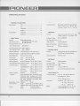
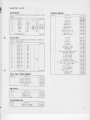
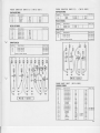
SPECIFICATIONS
t
Transistors,lCs and Diodes
TunerSection
FET
'.'.......''.,.......'....'.1
L o u d n e s sC o n t o u r
lCs....:...................................................-....-5
switchableto ON-OFF,boost12 dB ar
50 Hz, boost 9 dB at 10 kHz, with
VOLUI\4E control set at -40 dB
Transistors...
1t
AudioSection
25
Transistors.............................-...-,.............
FM Section
Diodes,etc..................................................5Circuitry
87.5 to
IHF UsableSenisitivity'l.7 pv.
FrequencyRange
Audio Sestion
Circuitry
Front end using FeT and 4 gang
variablecapacitor,lF amplifier4 lC
S i n g l ee n d e d p u s h p u l l
8O 100 wattstotal (lHF rating)
45I 13Owatts total
MUSTC
t OWerUUtOUt
'
PowerOutput
Continuous
(eachchanneldriven)
lmageReiection
I
'l08 MHz
87 dB (at 93 lvlHz)
SignaltoNoiseRatio 62 dB llH F ratins)
35W/35W80
AntennaInput
300 ohms{balanced)
continuous PowerOutput 28W + 28W8 o
(both channeldrivenl
Multiplex Section
3ow + 3(Mr451
HarmonicDistortion Lessthan0.5%(ar 1 kHz ratedoutput)
Circuitry
Mono Stereo Automatic selection
FrequencyResponse .t3 dB, from l0 Hz to 100k Flz (Ovoralll
PowerBandwidth
15 Hz to 40 kHz (AUXI
Hum & Noise
MAG:
betterthan 80 dB
{at rated output}
AUX:
better than 100 dB
Inputslmpedance
MAGneticPHONO: 3.3 mv.50 kO (1 kHz)
Time-svvitching tVpe de-modulator FM
'l
ChannelSeparation 4 2 d B ( a t k H z )
AM Section
Circuitry
Superheterodyne
525 to 'l 605 kHz
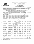
a n dA u d i oS e n s i t i v i tC
y E R a m i c P H O N O :2 4 m v . 1 0 0 k O { 1 k H z )
FrequencyRange
(for raredoutpot)
IHF UsableSensitivity18pV.
lrlcrophone:
5 mv. 100 kO {1 kHz)
TAPE |\4ONITOR:20o mv. 100 kn {1 kHz)
OutputTerminals
andjacks
Auxiliary:
20Omv. 100 kO {1 kHz)
MAIN lNput:
530 mv. 100 kO (1 kHz)
4 to 16 ohms
Speakers:
lape
Stereoheadphones
iack.Simultaneous
Recording iacks, equipped with TAPE
Taperecording/playback
MONITOBsvvitch.
(DlN
Pre Output jacks,
standardsl.
iack
Center Channeljack.
EqualizationCurves PHONO:
RIAA
BASS: boosr1l dB. cut 16.5dB (ätso Hz)
Tone Controls
TREBLE:boost1OdB, cut 9.5 dB lat 10 kHi)
cut 8 dB (ar 50 Hz)
Filters
LOW:
HIGH:
c u t 7 . 5d B { a t 1 0 k H z )
v
lmageRejection
77 dB (ar 1000kHz)
AntennaInput
Built in FerriteLoopstickAntenna
PowerSupply, Etc.
LineRequirements 110,'l'17,'130,220and240volts.
- 60 Hz
{switchable),50
21oVA, 190wafis (lMax)
Dimensions
Overall18" 1/16
459 mm (W)
5 " 1 1 / 1 6 1 4 5m m ( H )
14" 211
Weight
369 mm {D)
25 lb.2 oz 11.4k9
without package
29 lb.2 oz 13.2kg
with psckage
OI
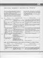
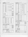
CONDITIONSFREQUENTLYMISTAKEN FOR TROUBLES
Noise: There ar€ a variety of noisesrelatingto the operationof
a hi-fi uni1. Th€seare g€nerallydivided into two types; (1) rhe
unit is faulw (a transistor or part is deteriorated)and {2) an
external lource of noise gives noise to the unit.
When a hi-fi unit producesan unpleasantnoise,it is otten ludged
that the unit is laulty, but statisticalrecords indicate that the
majority ot noises produced io hi-fi acoustic units resllt from
external sourci€sot noie. Due to the inherent high lensitivity
and rhe high lideliry in reproduction, the unit amplifies and
reproducesextranaousnois€s,howe\rers.nall, into definits output noise. lf your receiverproducesa noise, check according
to the tollowing table and tracr oul the sourceof nois6 for
an appropriatocorrectiveaction.
Tho table includes the condilions that mav be mistakenlor
troublesolthe unit.
suspectgd Sourca of Noise
Diagnosis and Remedy
Continuous or intermitt€nt
noi* like jjjill or zzzzzz-
. Ststics or list6nin9.
a Fluoresc€nt lamp, motor, or thermostat
may b€ us€d in hous€ or in th€ vicinity
In many cas€s, it is vory difficult to rsmov€ ths sou.c€
oi noiss. In ord€r to incroar€ th6 radio input la.g€. than
th€ nois€ lav€|, set up a good outdoor antonna and
make a compl6t€ grounding.
to
When a station is tuned
in, hum is mixod in tho
Program.
. Poor fluor€sc€nt lamp, motor, or slsciric
hsater mav b€ us€d in hous€ or neal lh€
Rsvgrslng th6 lin€ plug m6y occäsion.lly allwiat€ rhis
nois€ probl€m. usually lt Is vsry dlfficult to sliminsts
c
Hi$ing sound noise in AM
{modium wavel rscsptlon.
aTh€ fr€quoncy of 6n adjacsnt station is
interferlng wlth that of th6 srätlon bsing
tun€d in (1OkHz bsat interfsrsnce).
. TV set is on in the samo house where
th€ receivor,
lmDossible to rsmovs such intsrter€nco. ll th6 caua6 ol
such nols€ is in th€ TV sst. increase th€ distance
betw€€n the TV s6t and r6coiv6r,
Static noiso in FM roc€ption
{in particular. when 6utomoblles run clos€ to the
hous6l.
. Whit€ nois€s g€n€ratsd Jrom automobils
6ngin6s.
. Fadio fr€qu6ncv .ewing machins o. welding machlne b€lng us€d n€sr your hous€
In an area surrouncl€d by hllls or hlgh buildings, the
FM input signäls are very we€k. Thus ths nois€ limiter
i n t h € c i . c u i t l o s € si t s f u n c t i o n . S € t u p a n o u t d o o r F M
antenna h6ving many r€tlector €lsmsnts.
R€ceptlon of FM n€r6o
pJogtam contains morc
noi.€
FM mono
than
a Nots that ths s€wlcs ar€a cov€red by an
FM sterco broadcast ls sbout 50 ', of
that ot a regular mono bro6dcast.
lncrsaslng FM Input signal may all€viate this problem.
Use 6n erclusiv€ FM outdoor antonna inst€ad of the
lndoor T-än1enna,
Hum
o.
buzz.
Wh€n
swiichsd lo raclio rscsptionr
ths nolss wlll disappear.
. Poor connsctlon of shieldod wl.6 (a).
. J6ck connsctlon is loos€. (b)
. Llne cord o. fluo.€:cont lamp is near thg
shi€ldad wl.s.(c)
. Poo. grounding.{d)
a HAM ü6nsmltting nation or TV transtnitting station i3 nasr your hout€. (€)
corrrct the condition. .tat6d in (6), (b), {c) or {d}.
In cas€ of (6), r6po.t it to an official activity.
Output tone quality is poor
and mixed with noii€,
Trcbl6 13 not cl6ar.
. Stylus is worn out. {a}
. R€co.d ls worn out. (bl
. Dust adherei to stylus. lcl
.lmpropsr mounting ot stylus. (d)
a Stvlus pr€ssur€ ls not ptopsr. (€)
. The TR€BLE sound lav6l is too high.
Ch€ck (a) through (e) and cor.sct ths condition.
6
j
3
IE
3
Low€r the TR EBLE l€vei.
Further, watch the following conditions: Theseare also apt to be mistakenfor troubles of the unit.
Symptom
Pow€a 13 not tuhod on although tho powor 3witch is
s6t to oN.
su3poctod sourcs of Nois€
. Fuss is blo$rn. {a}
. Lln€plus is loo.€.(b)
a Distanco b€hiroon ths Jecord plavsr and
In playing8.gcoJd, incree
ing ths volums will caus6
the soeakers is too short.
aTh6 plece on whlch th€ rscord play€r oa
howling.
soeakers are set rs unstable.
Dlagnosis änd Rsmsdy
Checkla) and (bl and corr€rctthe condition,
Change ihe distance or r€arrang€ tha installation po3ltions ot tha unit änd sp€sk€rs. {lnstalling th6 r€cord
playor on € farm, solid sland may all€viate thls probl€m.)
Do nor enhancs ths BASS .ound lsv€l 6rcos.ivolv.
IrJIONEER
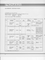
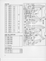
ALIGNMENTINSTRUCTIONS
ALIGNMENT OF FM SECTION
DisconnectOUTPUT terminal of front end from lN terminal of lF unit
Positionof Switch: SELECTOF ....'.' FM MONO
rvuTtNG.........
oFF
Volume Control Sstting: Fully Counterclockwise
Input
STEPS
1
Equipment
Connections
SweepGenerator
lN terminal
of lF unit
Frequency Level
4
5
7
Adjust
Oscilloscooe
10.7MHz
v
Alignment
Tt of lF Unit
T^
40d8
2
3
Dial
Seüing
Output
Equipment
Connections
Remarks
Adjust for maximum
sensitivity and symmetrical characteristics
@
terminal
80dB
Check svmmetry of curve
Removeelectrolytic capacitor Cl2 (ot FM lF tjnit 4.7l.lF) in detector circuit
SweepGenerator
lN terminal
of lF unit
10.7MHz
4odB
Oscilloscope
OUT terminal
Ta of
I F Unit
Adj ust the primary core
oJ T4 so that slope of
straight portion oi "S"
curue will become ihe
steepestand adiust the
secondarycore so that
the center of "S" curve
will concide with the
cenler of the marker.
Oscillosc€pe
(M)
terminal
T2 ot
trontend
Adjust for maximum
sensitivity and symmetrical characteristics
Connect OUTPUT tgrminal o{ fronted to lN terminal of lF unit
SweepGenerator
tr ol Fronlend
40dB
10.7MHz
8@B
8
40dB
Pointof
no inter'
terenceas
nearas
88MHz
Check symmetry oJ culve
Oscilloscape
OUT terminal
T4 of
lF Unit
Oscilloscope
L5 of
frontend
OUT terminal
CTa of
frontend
Adiust similarly
STEP 4.
to
Connect electrolvtic capacitor Cl2 {4,7llF)
lo
11
12
13
14
15
Signal Generator
FM Antenna
terminal
90lvlHz
106MHz
20dB
(400H2
30%)
90MHz
106MHz
Adiust for
deflection
maximum
Adiust for
deJlection
msximum
ReDeatSTEPS 10 and 1 severaltimes
SignalGenerator
FM Antenna
terminal
90MHz
I06MHz
ReDeatSTEPS 13 and 14 severaltimes
90lMHz
10dB
(400H2
30%l
't06MHz
Oscilloscope
OUT termin6l
Lr,Tr,
T2 ot
frontend
CT1, CT2,
CT3 of
lrontend
v.
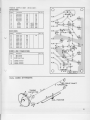
TJIONEER
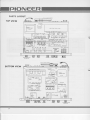
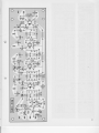
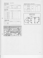
PARTSLAYOUT
TOPVIEW
MAIN AMP SHIELO CÄSE
BOTTOMVIEW
\3
o
o
zsegru
o: öö
L-l
,scao4\.i
n
use3P
^"" di
or
r$:b-u ,ses5
I
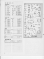
PARTS LIST
I
CAPACITt|RS
lN pF,lO
MlscrLLAI{t
0us
T O L E R A N C EU N L E S SO T H E R W I S EN O T E D
FM FRON'T END
Symbol
Cl
C2
C4
c7
.
Ca
3P
t 0 . 5 P 50v
220
3V
0.0015
50v
22ü
80v c52.O7
r.C
0.01
DCl4t(Vc€.003.c
0.01
DCI.4l{Vc43.003.c
0.01
DCI4XVc43-003-c
o.001
50v
0.00r
50v
Electrolytic
[4ylar
Electrolytic
C€ramic
Ceramic
Ceramic
{Vylar
lVylar
c64.030.c
v
RESISTl|RS
l N O H M l o a / 6 T O L E R A N C E%
, W UNLESS OTHERWISE
NOTED K:KO,M:l\4O
Symbo
R2
R3
R5
R6
R8
R9
Rlo
Rrl
Rr2
Rt3
Rt4
Rt5
R16
Rl7
RrB
t V p XU n i t
A I V T U N E RU n i t
IVUTING
Unii
I N D I C A T OURn i t
H E A DA m p U n i t
C o N T R 0 LA m p U n i i
C o N T R o LU n i t
P U S HS w i t c h U n i t ( A )
P U S HS w i i c h U n i t ( 8 )
I V A I NA m p u n i i
P o W E RS U P P L Y
Unit
wl1.028.c
tY12.025.4
w13.024.D
w14-m8,0
w18026C
|.|/18.012.0
wr5.049.4
w15-079.C
wl5-080
0
w15.081.4
wr5.082.0
wl5 060.4
w16.O22.4
Froni Panel
Diai Puttey
Foot
WooderCase
Dial Glass
DiatPointer
T u n i n gl , l e t e r( l o w e r )
T u n i n sl v e t e r ( U p p € r )
K n o b ,S e l e c t o r
K n o bT u n i n g
K n o bS
, p e a k e r sV,o t ! m ea, a t a n c e[ ,4 o d e
K n o bB
, assT
, r e b l e( L )
K n o bB
, assT
, r e b l e( R )
€P InputTerminal
4P InputTermina
1P InputTerminal
4 P A n t e n n aT e r m i n ä l
P i l o t L ä m p( f o r D i a l G l a s s )
PilotLamp(tof Selecl0r
P0siion FMSle€oindcalor)
P i l o t L a m p( f o r T u n i n g[ 4 e t e r )
Fuse 1A
.
Socket tor AC oIJTLET
Jack for Speaker
Jack for lVicrophone
. J a c kf o r H e a d p h o n e
Pilot Lamp Socket
F u s e H o l d e rl P
C o n n e c t o5r p
tv21.323.0
M42.027.A
tvt6l.0l7.0
M52r19.0
433.084.4
A3l 090.4
491-009.
B
491,008.8
412 1630
A l 2 -1 6 5 . 0
412.120.8
4r2.168.0
412-016-0
K22.013-C
K220n.A
K21.005.C
K11.018.O
E22.017.O
E22.A2r.a
E22.AO2.A
E2t.004.0
K82-007.8
K73.003.4
K72.O20.O
K72-O2t-B
K42.003
0
K91.005.O
K93.003-B
FM
C a r b o ni l l m
C a r b o nt i l m
c a r b o nf l l m
C a r b o ni i l m
C a r b o ni i l m
C a r b o nf i l m
c a r b o nf i l m
C a r b o nf i l m
C a r b o nf i l m
C a r b o nf i l m
C a r b o nl i l m
C a r b o nJ i l m
C a r b o nf i l m
c a r b o ni i l m
C a r b o nf i l m
c a r b o ni i l m
C a r b o nt i l m
C a r b o nf i l m
150K
I50K
100K
100K
1M
IM
68K
68K
410
4lo
150
150
6.8K
6.8K
1M
470
68K
68K
w52.004
0
COILSAI{t)TRAl{SFllRMERS
IF
UNit
Symbol
Power Transformer
i,latchingTranslormer
[ 4 a t c h i n sT r a n s l o r m e r
A M € r r i t e L o o p s t i c kA n i e n n a
H e a i e rC h o k eC o i l
C h o k eC o i l
T52 t58 C
T61 041 E
T61.041.E
r42 024 A
124 026 C
T24.030.C
swrTcHEs
Symbol
Descripiio
Sr
S2
S3
SELEcTOR
Switch
N f o D ES w i t c h
S P E A K E RS
Sw i t c h
L I N E V O L T A GS
Ee l e c t o r
sr3 029.c
s14035C
s11.022.t
s11.018-c
Pt|TEI{TIO
METERS
Symbol
Descfipiion
500KOdual,VoLUI\4E
50oKOdual, BALANCE
I
c85 054 C
c85 048 C
18
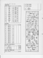
Flil tR0llTt1{0( Wl l -028)
CAPACIT(lRS
I
Symbol
D€scription
cl
ceramic
0.001
Ca
C4
Ceramic
Ceramic
Ceramic
6P
c7
CB
C9
Ceramic
Ceramic
Ceranic
Ceramic
Ceramic
Ceramic
Ceramic
Ceramic
Ceramic
Ceramic
ceramic
Ceramic
Ceramic
Ceranic
Clo
Cll
C12
cl3
Cr4
Cr5
Cr6
Cr7
cr8
C19
C20
CVI
CV2
cv3
cv4
CTt
cI2
CT3
CI4
F M t F U i l t T( W t 2 - 0 2 5 )
CAPACIT{|RS
25V
o.25P
50v
c47.005.,1
c47.005-,!
r0P
10P
r0P
5P
+ 0.5P
t 0.5P
+ 0.5P
t 0.5P
50v
50v
50v
50v
[email protected]
c43.002.c
c47.005.,
1P
0.01
25V
c47-005.I
5P
5P
:| 0.5P 50v
t 0.5P 50v
+ 0 . 5 P 50v
c64,036-E
c47,005,t
c47-005.t
c64,036,E
c64-036-E
c64.036-E
c64.036-E
c64.036-E
c64.036.E
c64.036,r
c45-m4-E
l
lAgans)
Cylinder
trimmer
RESIST(lRS
Symbol
R1
R2
R3
R4
R5
R6
R7
Re
R9
Rro
Rrr
Rr2
R13
D€scription
l00K
1M
220
3.9K
22K
IK
220
a.2K
2.2K
I,5K
22K
22K
3.3K
C a r b o nf i l n
C a r b o nf i l m
C a r b o nf i l m
C a r b o nf i l m
c a r b o nf i l m
C a r b o nl i l m
C a r b o nf i l m
C a r b o nl i l m
C a r b o nl i l n
C a r b o nf i l m
C a r b o nl i l m
C a r b o nf i l m
C a r b o nf i l m
%w
NW
NW
,Äw
\Ä\\
%w
%w
Symbol
Description
cl
C2
Ca
C4
C5
c6
C7
C8
C9
Cro
Clt
Cl2
C13
C14
Cr5
Ceramic
Ceranic
ceramic
[4ylar
Ceramic
Electrolytic
Ceramic
ceramic
C€ramic
C17
cr3
Cl9
C20
Electrolytic
Ceramic
Electrolytic
Electrolytic
Ceramic
C22
Symbol
T1
f2
Ll
L2
FIVlF Transtormer
RF coil
RF coil
L4
oSC Coil
19
Description
Qr
Q2
Q:
25K22.\ FEl
2SC46l(9 Transistor
2SC46l@ Tränsistor
D1
lS85 Variable
Capacitance
Diode
25!/
r6v
50v
C a r b o nf i l n
C a r b o nf i l m
C a r b o nf a l m
C a r b o nf i l m
C a r b o nf i l m
C a r b o nf i l m
C a r b o nf i l m
C a r b o nf i l m
c a r b o nf i l m
C a r b o nl i l m
C a r b o nf i l m
C a r b o nf i l m
C a r b o nf i l r n
R3
R4
R5
R6
R7
R8
R9
R1o
Part No.
47K
470
56K
470
56K
6.8K
2.2K
33K
22K
100
220K
820
3
Ct|IL AIIl1TRAI{SFt|RIiIERS
NW
%w
%w
XW
%w
%w
Symbol
Description
T1
f2
FM lF Transformer
FM lF Transformer
FM lF Transiormer
fa
Pärt No.
Symbol
Descriptjon
T73.020.C
T2I-013-E
r23-O26-L
r24.028.C
r24.0?3.c
r8.032.8
Q1
Q2
Q3
Qr
tA703E lC
4A7O3E lC
tA703E lC
tA703E lC
Dl
D2
o3
D4
D5
D6
lsl88 FM.l Diode
lSl88 FM.1 Diode
1 S 1 8 8F M - l D i o d e
lSlSa FM,1 Diode
lSI88 FM.l oiode
lSl88 FM.l Diode
Part No.
Part No.
r73.O22.C
173.O22.C
r73.O22C
T74.009.C
r24-029.C
0l00ESAtlDlCs
't22.013.E
l)I(ltlEAlIDTRAIISIST(lRS
Symbol
+2OoZ
Description
Rl
R F C h o k eC o i l
Description
I
4.7
r0P
I
RESISTllRS
811
R12
Rl3
CtlILSAIIt) TRAI{SFllRMERS
Symbol
0.01
25V
0.01
25V
0.01
25V
0.01
25v
10P
50v
0 . 1 ! 200/6 50v
0.01
25V
0.01
25V
0.01
25v
0.01
25V
I
50v
3P
]: O.25P 50v
o.0l
25v
100P
50v
0.01
25V
0.01
25V
0.0r
25V
4.7
l6v
300P
50v
(lTHE
R
Symbol
Description
Fr't Dersct
w53.040.c
A,O
\-'
E E
Lr T24-029
'i'r-"
0.ol
o---vrfu^rdL-o
flf ", c ,,u? o
C4o.ot
5
o
olt€
6
Dr tsl88
A,(o
g
b
CzztoP
o-ll-o
rytH
"---"-"ü*i ,"t,-l T
rÖ
ErEt
$ g
c.iNll
ol F-€ ioo
''
!
o---v\AH
cu
oli-o
001
s7
W+f,h''
g'
-^
d
ö
\o
r------r
o
I
o
I
e-ls-€
1/so
o o
!o
L-------J
R44?0
EEEI
R668K
o---{v\A{
l-
16
I
I
|
o
o---------Mts cr
"W":lt'f
?e
tl
ot'" cm..^f*f
If
F
- öl E l o { } €
ool
ö
r-------o-{ }-o
I o ooil
Cn3P
ilä
tt"
P1 lcx
I
ö o-ll-"
ö
l00P
cEE
o-l l-o
Ct6
0.0t
Cr5
?
I
üE"ölä**
11
Fl
?
s -.i?ET
Ä
T N
iI
I
Cll
l;l
I
o
R24?0
- I
;t'
ErD
|
Q
!t-------'r,,
o o olJ
ö
W:1ti
p
I
Ei'
rvs"
._____
I
o
o
o
_
I
?
l-
,ilä
:l!*s*'ü
Ä
r
i--+--"ri,'
l"
*Sps+s
w,ws3.o4o
I I
lO
l,.i;_:-a--ui:of":r-::::e
cre
lryl eA+ e----JW\.---o L
tlf,
13 llzs *ff' H
- Iin,
" +iirc
| ;U-
O
E H E 'E'''*"''C)
20
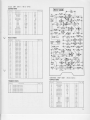
MPXUl{tr (Ufi3-024)
ctPtctI0fts
Srrnbol
Cl
C2
Ca
Ca
Cs
Ce
C7
Ce
Cro
C1r
C12
Crq
50v c1tc07.0
I
50v CEMXI MF5OV
50
0.047 !2eÄ 50v CQtlA473'{
clt0i00
0.01 t5%
a.622
Styrol
Elecirolytic
14ylar
Styrol
Siyrol
Elecirolytic
Styrol
Mylar
lvfylar
Electrolytic
Styol
S(yrol
Electrolyiic
Eleckolytic
0.01
2.2
0.0033 + 5 %
0.c022
a@22
22
0 0015
0 0015
447
4.41
o'sb
Ctt
cl50t00
c15011.0
cQMA222(50
CQMA2K50
CEMX2MF25V
cQsA152(
50
cQsAt52K
5C
CEMXR47llF50v
CEMXR4TMF5OV
D e s cirp i i o n
Rr
Rz
R3
P.(
R5
Rr
R7
Rg
Re
Rro
Rlr
RP
15K
15K
12K
C a r b o nl i l m
C a r b o nl i l m
Carbonlilm
Albot llm
C a r b o ni l ) m
Carboq{ilm
C a r b o ni i l m
C a r b o ni i l m
C a r b o ni i l m
C a r b o nl i l m
C a r b o nl i l m
Carbon
Jim
22n
,Fyls2r2v.t
4.lx
3.3K
10K
10K
15K
15K
r20
1K
RFYTPS4RIx
X
RF/{PS3R3K
K
RFXPSlOK.K
RFlrPS10K
K
RFZPSl5K.K
RFlf S15K.X
RF%PS12A.K
RFllPSIKK
c0rLs
Symbo
Ll
L1
L2
Synrbol
at
tv1PX.1C
POTTTTIO[|TTIR
5ymbol
D e 5 ! rp l i o n
4 . 7 K 0 S e m if i x e d
2I
R!
00022
c 9 20 5 1 , 0
oo
Cr
e:{-{
2'2ß3
ls(
^
0001t
RI
l0(
Rt
J, I
1.7X
t0x
.J
öOO
,
ooooooo
l&,-----l
Iäf
I u ' -' a o o
I
.oooooo
I
Rn120
o___lA&_____o o-{ }-o
I
o
o+
0
=
äf t ,*i'r.
0.0t*7
,*1"
ul"r
oooo
0Eo
o
oo o
oo
No
O
=
e{ Fo
0.0022
MC 1 3 O 4 L
0.0022
o{ to o-lw-_o
tl
D e s c rp t o n
o-1ts
ct
ol Fo
TI
t3
tI
l- l=
--t
IC
"Eo
2212sC!
Descriplion
T75.018.4
T 7 50 1 8 . 4
T 7 5 . 0 1A9
T75.015.0
T75.015.0
ol9
o.qhÄ
cto
".ro o
50
1 9 K H ,c o i l
l9KHz Coil
3 8 K H zC o i l
3 8 K H zF l l t e r C o i l
3 8 K H zF t e r C o i l
i'@
Ctl
€
Pa.t No.
RF/rPS15K.X
RFlrPS
15K.K
RF\/tP5 t2x.K
o{ lo
000r5
coo o
35V cE!ix2R2üF
35V
50v
50v
25V
50v
50v
50v
50v
017/50
äo o
IEStSI0RS
Syrnbol
-"ls
C*.
Part No.
Description
*tu!_=s
t3- 024
001
C+
ol l-o
001
il|JillrG
|JilrI (t|l18-026)
CAPACITORS
16V
4.7
35V
2.2
0 . 0 0 5 6 L 2 0 % 50v
Electrolytic
€lecirolytic
Mylar
RtstsT0ns
Descriplion
Symbol
Rr
\/
R2
R3
R1
R5
R6
R7
Rs
Re
Ro
Rll
Part No
33k
33k
330
10k
1 . 8k
10k
68k
C a r b o nl i l m
C a r b o nf i l m
C a r b o nf i l m
C a r b o nf i l m
C a r b o nf i l m
C a r b o ni i l m
C a r b o nJ i l m
C a r b o nl i l m
C a r b o nl i l m
C a r b o nt i l m
C a r b o nt i l m
Part No.
Symbol
Description
Ct
CAPACITOR
Electorolytic
470
Rr
R2
RESISTORS
C a r b o nl i l m
C a r b o nf i l m
470
470
Part No
Des c r i p t i o n
Syrbol
Cr
Cz
C3
üDrcATllR
U]ilT(Wr0-012)
Qr
2sA569-c Trantistor
D1
SD.IZ Diode
t6v
wr8-ot2
4.1k
2.7k
22k
TRAilSTST0nS
0escription
Synbol
a,
Qz
Q:
Part No
2CS870
2CS870
2CS870
22
A MT U f t EU
Ri l t T( W 1 4 - 0 0 8 )
CAPACIT(lRS
Symbol
c3
C4
C8
C9
clo
Ct!
u12
Cß
c14
Cr5
c16
Cu
c19
c20
c2r
Ca
c2t
Description
Coramic
Ceramic
Ceramic
Ceramic
cetamic
Mylat
Styrol
Ceramic
C6ramic
Ceramic
Ceramic
Ceramic
Electrolytic
Ceramic
Eiectrolytic
C€rämic
C€rämic
Ceramic
Cerämic
Ceramic
Electrolytic
Ceramic
Wlar
Mylar
Part No.
0.04
0.04
0.04
0.04
0.04
0.01
410P
0.04
0.04
0.04
0.04
0.04
l0
0.(B
10
0.04
0.04
2SC46l.l TränsiStOr
2 S c 4 6 0 . 1T r a n s i s t o r
2 S C 4 6 0 . 4T r a n s i s t o r
2SC460:ATränsistor
2 s c 4 5 0 . AT r a n s i s t o r
+ t@cz
25V
+ rEo96 25V
+t@
25V
+ r90% 25v
+ 19096 25V
+20% 50v
50v
+ rq'
25V
+l@
25V
+t@
25V
+ Lqo
+ rqo96
+ 7@96
1 N 6 0D i o d e
lN60 Diode
1N60 Diode
1N60 Diode
o5=Fo
3g'Ö"j*j
v
äv
r0v
Ct
_g o--l t--o
0r4
!J_ e
o---{v1A----o 9
|
25V
16v
+ rEo
23U
+ rgD
25V
50v
47P
50v
0.04 + Lqo96 25V
2m
l6v
0.04 + 190?/6 25V
o.oo4 xbol
50v
o.oo2 x20% 50v
ooä
11160
Fl.lx
t:::tfi+lt;*=li
ön.
ol
lo
|
o----r/\^ ----€ ö
33(
i? $(
O O--------------o--ft\^t---o
p
|
I
ö
ä4-#r-{"ä.trffi
o=rllts
RESIST(|RS
Synbol
KI
R2
lß
R4
R5
R6
t17
KA
t(9
Rto
hll
ND
R14
Ä15
R16
Ru
R18
Rr9
R20
R2l
Ru
l(23
R24
R25
R26
R2i
R28
Description
Part No.
C a r b o nt i l m
Carbonfilm
Carbonfilm
Carbontilm
C a r b o nf i l m
Cärbonfilm
Carbonfilm
Carbonfilm
Carbonfilm
Carbontilm
Carboniilm
4.7K
1K
IK
IK
4.4
22K
Carbonfilrh
Carbontilm
Carbontilm
Carbonlilm
C a r b o nt i l m
Ca.bon lilm
Carbon film
Carbonfilm
Caöon film
Carbonfilm
Cärbonfilm
Cäöon film
Caöon film
Cärbonfilm
Cärbonlilm
Carbonfilm
Carbontilm
4m
IK
lm
4.7K
l@K
470
IK
4.7K
27K
2R
470
470
1K
100
3.3(
6.8K
220K
T1
r2
Description
DI()t|ES
AIIDTRAIISISTt)RS
23
c.4rp
T"
o o-li--€ OOt
turx
o--nv\l-----o
R,! t(
ui**,ti;
*l;"'f
-J
l=ö?.1:fS_X
1K
1K
33K
p.
MWRF Coil
MWOSCCoil
AM lF Transtormer
AMlF Transtormer
AM lF Transformer
p EO o, U
I n
I
o |
I o
e I O O
ffi
o s-------rlv\A---o
I
gq' -täLJ -l"[=
lT
ffil1ct'^
-__"5r-_,
IlF
111.'-,--o cß,,/,.Rö
9
9.__{iE- " I
\t
lfl:: :ifi-!,.*ff.
zwts
Ö | O O O llTtla
L-JFTöl.
-vW;*
---U;f
o. !4
l^ll-to
'ät o-r^/Vl--{
F o(Ob3
8?
o--fv\F--o
c6
o{Fo
iz. tK
27x rr rrco
dts
t?p L
c2l
ot{ }<
a-{
}-{
Ooil rr
*iij.J,+;ith
ooE
C()ILSAI'It)TRAI{SFtlRMERS
Syn$ol
R! l{
Oqor
s----lv\A----o
el Fo o----lv\t-----o
IOOOIpQR!.7r(
I r
I tJ-- e--r^tv\-----o
Part No.
T4r.@8-C
Td].m7.c
T71.025.C
[email protected]
r72.017.C
lo
.olto
l?
rore:r o I
"ffi"e.a.--{ lf{
o-*o ?
|
^FtE'
;öö
3
3
o
o
og=o
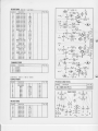
H E A 0A M PU l ' l r (TW 1 5 - 0 4 S )
CAPACITtlRS
Symbol
cl
Cz
c3
C4
C5
C6
c7
Ce
C9
Clo
cLl
CL2
c13
C14
Electrolytic
E e c t r oy t i c
ElectroLytic
Electrolytic
t',,lytar
lviylar
N,lyar
[4y ar
Electrolytic
ELecirolytic
Elecirolytic
E l e c t r o l y ct
E l e c t r o l y lc
cl6
ct7
l0
10
100P
100P
I00
100
001
0.01
0.003
0.003
330P
330P
10
i0
10
10
50
Rl
R2
R3
film
Carbon
C a r b o ni i l m
C a r b o nf i l m
C a r b o nf i l m
R3
RL2
c a r b o ni i l m
C a r b o ni l m
c a r b o nf i l m
RL5
RL6
C a r b o ni l m
RL7
RIB
C a r b o ni i l m
Rt9
c a r b o nt l i n
R22
R24
R25
R26
C a r b o ni l m
C a r b o nl i l m
c a r b o nf l l m
Carbon
iilm
3.3K
3.3K
4taK
41AK
lN1
ltv
330K
330K
470K
470K
470
410
56K
56K
4.1K
4.1K
3.3K
3.3K
2toK
27AK
22K
22K
2.2K
2.2K
l0K
10K
4tK
47K
TRAI'ISIS
T()RS
S/mbo
Qi
a,
Q3
Q4
o------vl A---o
Rlr3.3K
R26to|(
e=-r/v1H
RaaI1K
D e s c rp t i o r
2 S C 4 5 8C
tG
o18Transisto
CorBlransistor
25l]45iJLG
2 S C 4 5 8C
LG
orB
Transislor
2 S C 4 5 8C
LG
orB
Transßtor
2 S C 4 5 8C
LG
orS
Transßtor
2Sl]458L
CC
orS
Transrstor
oo
0No
100t6
L
S*e
o
e----rlr'f
Description
R5
Rll
4?0x
R23.3X
lol15
,:s5
sol25
co
qFo
.3;
o--/St--:-€
I
qts
o-i\^^-----o
c--r^ll-----s
R2tZzX
Cn 10/15
eo o .--iffij.
clr
R7330K
/ro\
o---nw---o
a$)o
gOo
ol l-o g
Re4?oK
f
n r+r r O
eP gör
+,o--vw-----o
3äöPß o (b
c--rAf'/.------€ HPp,
o-----VW-----€
Rr 3.3K
F---vt l----o
Rrs4lX
ä4"*
e--nVH
Rr356K
0.01
Rt! Z?oK
elFo
o---lW:----o
o-{}€
0.003
R232.2K
R2sloK
o o
rNl
R2ozloK
o----vt/H
cro
qF
o_--r^/vH
Rzt,z.2r nU.
R274?K
F--l\M-----o
,o1e
e----v\ff
Rtz 221<
o o rrno
oo
R6 4?X
Cr4i
o---vltf--.--o
O O zjn0
RESISTt|RS
Symbol
10v
l0v
50v
50v
6V
6V
50v
50v
50v
50v
50v
50v
l5v
r5v
15V
l5v
25V
S =*"
5 6ö
RsrM
o----rMl-----o
R!4?ox
o--/V\l-----o
c 0 N T R 0ALM PU N t T( W 1 5 - 0 7 9 )
CAPACIT()RS
Symbol
Descripiion
cl
C2
c3
c4
c5
E l e c t r o l y ct
Electrolytic
Ceramic
C6
C7
C8
c9
Clo
Crl
C12
c13
Cr?
C15
Cr6
Cr7
CiB
E l e c t r oy t c
E l e c t r o L yct
ElectroLytic
E l e c t r oy i i c
E l e c i r o l y tc
E l e c t r o l y tc
lvlylar
Mylar
[4ylar
[,lylar
E l e c t r o l y ct
Electrolyiic
Electrolytic
Electrolyiic
4.47
o.41
r0P
t0P
o.22
022
100
100
I
i
0.0047
0.0047
0.0047
0.0047
33
33
50
50
25v
25V
50v
50v
25V
25V
35V
35V
16V
l6v
50v
50v
50v
50v
6.3V
25V
25V
24
RESIST0RS Note:
LN......Low
Noise
Synbol
RI
R2
tß
R5
R6
R7
R8
K9
Rlo
Rtr
K12
Kl3
R14
R15
K16
nl7
R18
R19
R20
R2r
t<22
K23
R24
R25
R26
ß21
R28
R29
x30
lt3I
R3?
Cr+ H
Description
C a r b o nf i l m ( L N )
Carbonfilm (LN)
Carbontilm (LN)
Carbontilm (LN)
Carbontilm (LN)
C a r b o nf i l m ( L N )
C a r b o nf i l m ( L N )
Carbonfilm (LN)
C a r b o nf i l n ( L N )
Carbonfilm (LN)
C ä r b o nf i l m ( L N )
Carbontilm (LN)
Carbonfilm
C a r b o nl i l m
C a r b o nf i l m
C a r b o nf i l m
Carbonfilm
C a r b o nf i l m
C a r b o nf i l m ( L N )
C a r b o nl i l m ( L N )
C a r b o nf i l m
Carbonfilm
Carbonfllm ( LN)
Carbontilm (LN)
Carbontilm
Carbonfilm
Carbonfilm ( LN)
C a r b o nf i l m ( L N )
C a r b o nf i l m
C a r b o nf i l m
C a r b o nf i l m
C a r b o nf i l m
Qt
Qz
Q3
Qa
I
t**I
oo
Wtär=+'ll
- =l=*{"_**D__*._.
1K
IK
330K
330K
33K
33K
8,2K
8.2K
IK
IK
IK
IK
2.2K
2.2K
6.8K
6.8K
6.8K
6.8K
1K
IK
l.8K
1.8K
330K
330K
41K
47K
8.2K
8.2K
1.5K
L5K
330
330
R,o
l(
I
I
";
S
t*t
H
.if3"
fl68.zx
o
-: =S f t*+
,,,oä,
*'r,
o-1Fo Hv\F.{
c8
o--N:-o
ö
too/ts
filrlt* n
"
Raotf
I
?
.I
"-------lW-"
-l' --jt,fil_c e*c
x p le I lltl
c6
|
$*Dt l*
;FlsJ *;F
-'cls:=r
nf,
rl . l=
J _ffi_
(n
| |
oo
_
s*.
I ___y^fl-ö; g!.1l!
"_"*fe
I _$*
Jeis*i5*-" 'PJ lf ,l
R s 4 ?^xo
o---\t\^F
I
ö
cr 4?00p
Cll
4?ooP
- e-lFo
o o
c,,
Description
R'7
Rr7
'(
f Sl
"l
üJ!
o
Ä
---o
6aK
hlv\
ä"*,r *-;scr- #
oo
Part No.
c
St*"
Rer(
.=ä----+
L
2SC87l.BL
2SC87l.8L
2SC8i0.GR
2SC870.GR
_
oo
R' 8.2K
A----o--+\A---o
o--?S_
cg
,7
| .-Nr "We t"
ö
., Jltrl. {.t; f s
"04lzs
{b
c0r'rTR0L
uNrT(w15-080)
o,*
!
o__-_1A l-_o
l-
V
ö
CAPACITl|RS
Symbol
Cl
c4
c8
c9
Cro
Part No.
Description
Electrolytic
Electrolytic
Mylar
Mylar
Mylar
Mylar
Mylar
Mylar
Wldr
Mylar
3.3
3.3
0.0022
0.w22
0.01
0.01
0.033
0.033
0.1
0.1
25v
25V
50v
50v
50v
50v
50v
50v
50v
50v
P(lTEI{T
I(lMETERS
Symbol
Description
Description
xl
R2
x3
Carbonlilm
Carbonliln
C a r b o nf i l m
C a r b o nf i l m
Carbonfilm
Carbontilm
C a r b d nl i l m
Carbonfilm
x5
R6
x7
fia
25
Part No.
r00Ko,dual(B.loir,"r
)
l00KO,dual(rR%oLnfoJ
VRI
?
lr=F
d-
9le
"T=
??
5{:{
,,
Part No.
l0K
10K
2.2K
2.2K
4.7K
4.7K
470
470
ca7-o24.c
c87,024.C
I w r s- o s ö l
I
9lQ
RESISTl|RS
Symbol
9
6elq
TRAI{SISTtlBS
Symbol
_v\H
e+o
Part No.
'? "?
| O|
o-{F---o c'
o.' *-1F
0,!33
co
o--lF ---6 c.
O
or-lF??
0
c
l: l"
0031
i.frr
.:1"F- o*e *+e
R3'1r{
t5
'l
rüi 3ä-
,.1
ä!?:3
|
|
Frr'v!---o
t*
oo
,
I
I
I
I
R.4t(
34
GND
P U SS
HW T T U
T () ( W r5 - 0 8 2 )
C rH{ r B
CAPACITllRS
PUSH
S W T T CUHl { r TA() ( W t5 - 0 B)l
CAPACITl|RS
Symbo!
Description
Cr
c2
Ceramic
Ceramic
[,lylar
Part No.
82P
82P
0.01
0.01
c4
50v
50v
50v
50v
Synbol
Description
Cr
Mylar
RESIST|lRS
Description
Rl
R2
R3
C a r b o nt i l m
C a r b o nf i l m
C a r b o nl i l m
Carbonfilm
C a r b o nl i l m
C a r b o nl a l m
R5
R6
Description
R1
R2
Part No.
68K
68K
27K
27K
3.3K
3.3K
swtTcHEs
0escription
Symbol
s1
S2
Symbol
Description
S2
S3
P U S HS w i t c h
PIJSHSveitch
P U S HS w i t c h
s31.023.C
s31.023-c
s3r,023.(
Knob for Push Switch
419.079,(
s31.023,(
Knobfor PUSHSwitch
417.079-(
r3
t4
5o6
-7
23
o
oo
oo
OO
41
oo
"f'4
oo
3
-
54213
ooooo
ooooo
ooo
ooo
Part No.
PUSH Switch
P U S HS w i t c h
Part No.
ilsE
t 50(
r50x
C a r b o nf i l m
C a r b o nf i l m
swtTcHEs
10 l2
oo
oo
50v
50v
0.039
0.039
RESISTl|RS
Symbol
Syrnbol
Part No.
9-
9-
a *t36 . r * EI o
öo
7
oo
oo
IT
*+är+=
JI
oo
6
o
lwf5- oBr-l
M A üA
{ M PU l i l T( W r 5 - 0 6 0 )
CAPACIT(lRS
o
oo
o
o
o
o
o
o
oo
o
o
o
o
oo
Symbol
Cr
c2
Ca
c5
wt5-o8l
C7
c8
c9
Clo
Clr
C12
cl3
c14
c15
cl6
cl7
Cr9
C6
Part No-
Description
Electrolytic
Electrolytic
Electrolytic
Electrolytic
Elect.olytic
Electrolytic
Electrolytic
Electrotytac
Ceramic
Ceramic
Electrolytic
Electrolytic
Electrolytic
Electrolytic
Ceramic
Ceramic
Mylar
Mylar
Ceramic
Ceramic
3.3
3.3
lm
IM
3.3
100
1m
100P
lmP
100
1@
1000
1@0
47P
47P
o.a2 + rgJoz
o_42 + rgD'ä
lmP
100P
l0v
10v
50v
50v
25V
23V
50v
50v
50v
50v
3V
3V
35V c52
35V c52
50v
50v
50v
50v
50v
50v
26
RESIST(lRS
Symbol
KI
R2
n3
R4
R5
R6
R,
R8
R9
Rro
Rlt
R12
R13
Rrl
Rl5
Rt6
Ru
Rr8
R20
R2r
R2
R23
R24
R25
R26
R2t
R2s
R29
R30
Description
Carbontilm
Carbonfilm
Caöon lilm
C a r b o nf i l m
Carbonfilm
Carbontilm
C a r b o nl i l m
C a r b o nf i l m
C a r b o nl i l m
C a r b o nf i l m
C a r b o nf i l m
Carbontilm
Carbonfilm
Carbonfilm
C a r b o nf i l m
C a r b o nl i l m
Carbonlilm
C a r b o nf i l m
Carbontilm
C a r b o nf i l m
Carbonfilm
Cärbonfilm
Cärbonfilm
C a r b o nl i l m
Carbonfilm
Carbofltilm
C a r b o nf i l m
C a r b o nf i l m
Cärbonfilm
C a r b o nf i l m
tu1
R?
R33
R3a
R35
K35
R37
R38
R39
R40
Carbonfllm
C a r b o nf i l m
C a r b o nf i l m
C a r b o nf i l m
C a r b o nl i l m
C a r b o nf i l m
Part No.
2.2K
2.2K
2.2M
2.2M
1@K
1mK
r8K
18K
l5K
15K
150
t50
820
820
39K
39K
3.3K
3.3K
4.7K
4.7K
150
r50
22
22
150
150
22
22
150
150
0.5
0.5
0.5
0.5
15K
I5K
8.2K
8.2K
10
t0
XX
\{/
gös
;
xw
xw
tY
ö
yw
xw
xw
%w
n
ll
2W
2W
2W
2W
2W
xw
%w
0t00Es
All0rnAl{slsT0Rs
Symbol
Qr
Qz
Q3
Q4
Qs
aE
Qr
Qa
Qg
Qro
Ql1
Ql2
Dr
O2
Description
Part No.
2SC732 Transistor
2SC497.O
Transistor
2SC497-O
Transistor
2SC497-0
Transistor
2SC497.0
Transistor
25 497.0Transistor
25 497-0Transistor
2SC793.Y
Transistor
2SC793-Y
Transistor
2SC793-Y
Transistor
2SC793-Y
Transistor
SIV-3(Varistor)
(Varistor)
STV.3(
P|lTEIITIl|MT
TERS
Symbol
Description
VR2
30fO, semifixed
3oKO, Semifixed
50O
VR.
27
50O
Semifixed
Semifixed
Part No.
c92-024-B
c92-024.8
c92.043-O
c92.043.C
FUSf
n
l+----o'\r---------+l
ll
P(lWERSUPPLY
U}IIT( w 1 6 - 0 2) 2
CAPACIT{)RS
Symbol
Cl
C2
c4
Description
Electrolytic
Electrolytic
Electrolytic
Electrolytic
Electrolytic
Electrolytic
C7
Cto
C
ceramic
Ceramic
Ceramic
Ceramic
Part No.
Rl
t12
R3
5tov
35V
2&
25V
2m
25V
28
15V
2m
25V
0.@1
50v
0.01 + rEo% 500v
0.01 + r9o% 500v
0.01 + lEooz 500v
0.01 + 1E0% 500v
oo
oo
oo
K5
R6
R7
KA
R9
Rro
oo
Part No.
680
22R
33K
l8K
3.3K
39
5.6
1K
33
Description
lS338QZener0iod6
QI
Q2
Q3
2SC€5 Transistor
2SC905lransistor
2SC485Transistor
, Wr
o*o
'
q
Ro
Part No.
oo
2201t5
Sf s u-ro *.SH
.c6
22o/2s
I
loDs
Ö ^ e-ltH
d )9.- tsrra
Hu\Y/s
",o986
cz
HlAl e "o
\Zo
dN-€
S
I|oo/3s
n,
äs
-----v\M-----------o
16802w
I
H44r
'5^
SB.3PDiode
D2
D3
=T-'--#
*t* ;fi*
It
22U25
cl*N-.
_9
t
|
-1*
S*,s
|
qo
-l
t)I()t)ES
AI{t|TRAl{SIST()RS
Slmbol
d{-
?
=Io9?
iö
2W
D2
s8-3P
Pfi
ööö
1@
Description
C a r b o nf i l m
C a r b o nf i l m
Carbonfilm
Carbontilm
Cärbonfilm
C a r b o nf i l m
C a r b o nf i l m
C a r b o nf i l m
Carbonfilm
Carbonfilm
C0 0.0|
HF--o
lm
RrsrsT0Rs
Symbol
o
R2o
e____r^lv1-----o
oo
22K
cs
g---JF---o
?
oj'
9*t
.
"
tttl
L-äJ-|<J
Cl
#S"
tnlfl
ü
orsB-3P
lffila
cC
DIAL CORD STRINGING
IVE SHAFT
TUNING
CAPACITOR
DIAL POINTER
28
IrJIONEER
9
PIONEEFT
ELECTFTONIC
CclFIPOFIATIGIN
Ohta.ku,Tokyo,Japan
l5-5, 4-Chome,ohmori-nishi,
.
PIONEERELECTRONICS
U.S.A.CORPORATION I
N.Y.11735,
U.S.A. |
1,t0lmitLst., Fami!gOa!9,1.1.,
(69K05F04D)
(EUROPE}AG.
PIONEERELECTRONIC
Zurich,Switzerland
59, ForchStrasse,8032
PFINTED IN JAPAN
<R12-048-C)