1
Download v. www.rainers-elektronikpage.de ; gescannt von Rainer Fredel
Service – Unterlagen
Röhrennetzteil
FLUKE 407 D
Diese Unterlagen wurden mir von Herrn Wolfgang Gisdespki und Herrn Ingo Schmitz zur Verfügung gestellt.
Vielen Dank!
Dipl. – Ing. H. R. Fredel
Download v. www.rainers-elektronikpage.de ; gescannt von Rainer Fredel
Download v. www.rainers-elektronikpage.de ; gescannt von Rainer Fredel
Download v. www.rainers-elektronikpage.de ; gescannt von Rainer Fredel
JOHN
FLUKE
P. O. Box7428
M F G. C O . I N G.
Seattle33, Washington
February 1, 1964
MODEL
4O7D
I W E R S U P P LY
Serial no.
and above.
Download v. www.rainers-elektronikpage.de ; gescannt von Rainer Fredel
@
copyRtGHT,JoHNFLUKEMFG.co., lNc.,1970
Download v. www.rainers-elektronikpage.de ; gescannt von Rainer Fredel
407D
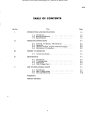
TABLEOF CONTENTS
Title
Section
I
INTRODUCTION AND SPECIFICATIONS
1-1. Introduction
t-2, Receiving Inspection
1-3. Specifications. . .
u
OPERATING INSTRUCTIONS
2-t.
2-2.
2-3.
2-4.
m
Controls, Terminals, and Indicators.
Operation
Use as a General Purpose Laboratory Supply.
Calibration of Voltmeters.
1-1
1-1
1-l
1-1
2-L
2-t
2-2
2-2
2-2
3-1
THEORY OF OPERATION
3-1. Circuit Description
rv
Page
3-1
4-t
MAINTENANCE
4-L. Introduction
4-2, TroubleshooHng.
4-3. Calibration
4-4. Tube Voltage Chart
LIST OF REPLACEABLE PARTS
5-1. lntroduction
5-2. How to Obtain Parts
5-3. Use Code Effectivity
WARRANTY
CIRCUIT DIAGRAM
ll
4-1
4-l
4-3
4-3
5-1
5-1
5-1
5-14
Download v. www.rainers-elektronikpage.de ; gescannt von Rainer Fredel
Download v. www.rainers-elektronikpage.de ; gescannt von Rainer Fredel
407D
I I S T O F I T L U S T R , AT I O N S
Figure
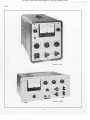
Frontispiece
.
Title
Page
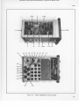
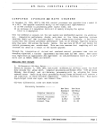
Model 40?D Power Supply
tv
2-L
Controls, Terminals,
2-L
4-L
Troubleshooting (sheet 1 of 2)
4-L
4-L
Troubleshooting (sheet 2 ot 2)
4-2
4-2
Tube Voltage Chart
4-3
5-1
Final Assembly (Cabinet Model).
5-3
5-2
Final Assembly (Rack Model)
5-4
5-3
Rectifier Printed Circuit Board Assembly
5-6
5-4
Front Panel Assembly (sheet 1 of 2)
5-8
5-4
Front Panel Assembty (sheet 2 of.2)
5-9
5-5
Amplifier Printed Circuit Board Assembly
5-12
5-6
Capacitor Board Assembly
5-13
and Indicators .
llr
Download v. www.rainers-elektronikpage.de ; gescannt von Rainer Fredel
40?D
o
tll (tI
fl,r t,ti
j[Ö','
il[
,,ill
MODEL 4O7D
.S\sls*\.
\ss{!*rsg\
ü,
.
I
o
! o
MODEL 4O?DR
Download v. www.rainers-elektronikpage.de ; gescannt von Rainer Fredel
407D
S E C T T O NI
I N T R O D U C T I O NA N D S P E C I F I C AT I O N S
1-1. INTRODUCTION
The Model 407D is an extremely stable, highly regulated source of DC voltage in the 0 to 555 volt, 0 to 300
milliampere range. The power transformer is a specially designed, conservatively rated unit, provided with
a dual primary for operation from either 115 or 230
volts. Precision wirewound resistors using Evanohm
alloy are used in all voltage sampling resistors and
at other critical points in the circuit. This perrnits
the use of calibrated output voltage controls and insures
This stability plus the
excellent long term stability.
high degree of isolation of the output from variations
of either line voltage or load current enhance the use
of the power supply. Two auxiliary outputs are also
provided: a dual-range, negative-bias output with
e x c e l l e n t r e s o l u t i o n , a n d d u a l 6 . 3 VA C , 5 a m p e r e
output which can be operated in series or parallel.
These features make the Model 407D an ideal Iaboratory
or general purpose power supply.
I-2.
INPUT POWER: Approximately
full load, 100 watts standby.
425 watts at
INPUT VOLTAGE: 115 or 230 VAC +L!Vo, 5Q/60
cycles, single phase.
L I N E R E G U L AT I O N : 0 . 0 0 5 7 oo r 1 0 m v, w h i c h ever is greater, for +1070changein line voltage.
LOAD REGULATION: 0.lLVo or 20mv, whichever
is greater, for full load change.
METER: 4-L/2 inch, 0-600 volts, 0-300 milliamperes.
MAIN OUTPUT CURRENI: 0 to 300 milliamperes.
IvIAIN OUTPUT VOLTAGE:
0 to 555 volts.
OUTPUT IMPEDANCE: Less than 0.5 ohm at
300 milliamperes load. (DC to 100KC).
RECEIVING INSPECTION
This instrument has been thoroughly checked and tested
before being shipped from the factory. Immediately
aJter receiving the instrument, carefully inspect for
damage which may have occurred in transit. If any
damage is noted, follow the instructions outlined on
the warranty page in the back of this manual.
OUTPUT POLARITY:
ground, or floating.
OUTPUT CONNECTORS: Binding posts on 3/4
inch centers. Also terminal strip at rear on
rack model.
RIPPLE:
1-3. SPECIFICATIONS
PIus or minus relative to
500 microvolts RMS maximum.
STABILITY: O.Itflo per hour and 0.05% per day.
a. ELECTRICAL
AUXILIARY OUTPUTS:
(DC) 0 to minus 250 VDC. Maximum auxiliary
output is 5 milliamperes at -250 volts. Line
regulation of 0.00570at maximum output. Maximum ripple is 500 microvolts. Output impedance
0 to 50r 000 ohms, dependingon setting of BIAp
control. At 250 volts, load regulation is 0.017o
for 5 ma load change.
(r'C) Two independent 6.3 VAC, 5 ampere outp u ts . M a y b e s e r i e s o r pa r a l l e l c o n n e c t e d .
Each insulated for 1500 volts RMS.
CALIBRATION ACCURACY: r.0.\Vo from 50 to 500
volts when selected by the 0-500 volt control.
VOLTAGE CONTROLS:
Ten 50 volt increments
0 to 55 volt vernier
0 to 0.55 volt vernier
VOLTAGE RESOLUTION: t2. 0 millivolts.
b . MECHANICAL
SIZE:
Cabinet model; 9-3/4" W x 13" H x 14" D
Rack model; 19" W x 8-3/4" H x 16" D
WEIGHT:
Cabinet model; 39 lbs.
Rack model: 48 lbs.
1-1
Download v. www.rainers-elektronikpage.de ; gescannt von Rainer Fredel
Download v. www.rainers-elektronikpage.de ; gescannt von Rainer Fredel
407D
SECTION II
O P E R AT I N GI N S T R U C T I O N S
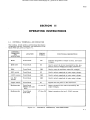
2-L.
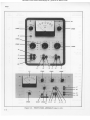
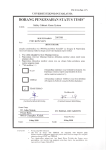
CONTROLS, TERMINALS, AND INDICATORS
The location, circuit symbol, and functional description
of external controls, terminals, and indicators on the
Model 407D are given in Figure 2-1.
CONTROLS
TERMINALS
AND
INDICATORS
LOCATION
CIRCUIT
SYMBOL
FUNCTIONAL DESCRIPTION
Meter
Front Panel
M1
Indicates magnitude of output current, and output
voltages.
MTR CKT
Front Panel
S3
Used to select the circuit monitered by Ml, alscr
used to remove voltage from output connectors.
BIAS
Front Panel
R68
Used to vary the auxiliary output DC voltages.
500V switch
Front Panel
S2
Used to select magnitude of main output voltage.
0-55V vernier
Front Panel
R62
Used to select magnitude of main. output voltage.
0-0.55v
vernier
Front Panel
R63
Used to select magnitude of main output voltage.
Toggle switch
Front Panel
s1
Applies AC line power to the instrument.
Binding posts
Front Panel
(Middle and right
side)
Jl thru J6
Output connectors for main and auxiliary DC
output voltages.
Binding posts
Front Panel
(Left side)
J7 thru J10
Output connectors for two 6.3 yAC sources.
Figure 2-1. CONTROLS, TERMINALS, AND INDICATORS
2-7
Download v. www.rainers-elektronikpage.de ; gescannt von Rainer Fredel
40?D
2-2.
OPERATION
a. Connect the instrument to a single phase 50 or
60 cycle source of proper line voltage. The power
transformer Tl in the Model 40?D has a dual primary.
For operation from 115 volt porüer line, the two primaries are connected in parallel; for operation from
230 volt portrer line the two primaries are connected
in series. A label is attached to the outside of the
baclr,panel which states the voltage for which the transformer has been connected. To change the connection
of the primaries, remove the instrument from its case
and refer to the schematic diagram in the back of this
manual. When operating from 230 volts, change the 5
ampere slo-blo fuse to a 2 ampere slow blow fuse.
b. Select desired output voltage on the three calibrated
voltage controls.
c. Set MTR CKT switch to IIV OFF position and turn
PWR switch ON. The pitot light shonld illuminate. After
approximately 30 seconds, turn the MIR CKT switch to
HV position and the desired voltage will appear at the
0 to 555 volt output posts. The 30 second delay before
turning on the high voltage is higtrly desirable to permit
the tubes to warm to operating temperature before
applying high voltage to the tube plates. This permits
better control of output voltage during turn-on, and
prolongs the life of the tubes.
d. The first calibrated output voltage control on the
front panel of the instrument is accurate to better than
x0.\Vo of its reading, whereas the panel meter is accurate to $% of.full scale. Consequently, the voltage
controls are approximately 6 times as accurate as the
meter, and should be relied upon in preference to the
meter to indicate the magnitude of the output voltage.
Should a large discrepancy between meter reading
and dial position appear, refer to Section IV, paragraph
4-2, Troubleshooting for correction procedure.
e. When turning the power supply on or off, always
turn the MTR CKT switch to the IIV OFF position before
turning the PWR suritch off. This is a precautionary
measure to prevent the possibility of damage to a sensitive load from overshoot in the output voltage.
2-3.
USE AS A GENERAL PURPOSE LABORATORY
S U P P LY
Four different voltages are available at four sets of
binding posts on the Modet 407D. All four may be t'sed
simultaneously at maximum output current with no derating required under any conditioyrs.
a. Main Output Voltage. This is 0 to 555 volts, 0
to 300 milliamperes, available at the right hand binding posts. This voltage is adjusted via the three calibrated controls. Regulation is 0.01% or 20 miltivolts
for full load change, or 0.005% or 10 mv for r10% line
voltage change. Output voltage may be monltored oq
the panel meter by setting the MTR CKT switch to the
HV position. Output current may be monitored on thö
300 ma meter scale by turning the MTR CKT switch to
2-2
IHV. Output voltage may be removed from the binding
posts by turning the MIR CKT switch to IIV OFF. This
opens the circuit between the regulator and the positive
binding post. An anti-arcing circuit biases the output
tubes to cut-off before the output circuit is interrupted,
thus preventing switch arcing.
b. Auxiliary Output. 0 to minus 250 volts at 5 ma
ma:rimum, available at center three binding posts. This
control is not calibrated, since the output voltage is
derived from a 50r000 ohm potentiometer and is therefore sensitive to load current. Line regulation is
0. 00570or 10 millivolts for *10% line change. With
control turned to maximum (250 volts), the output is
regulated to 0.lLVo for a load change of 5 ma. This
bias voltage may be monitored on the panel meter by
setting the MTR CKT switch to BIAS. There is a 10to-1 voltage divider across this minus 250 volt output,
which provides a 0-to-25 volt source. Since this is
derived from a voltage diirider, , it is also sensitive to
to load current. To determine the output voltage at
this tap, divide meter reading by 10. The main output,
when used with the 250 volt auxiliary output, provides
a positive, negative, or floating output of 250 to 80b
volts at 0 to 5 milliamperes, with no change in line,
Ioad, or ripple specifications. The plus side of the
250 VDC output is connected to the minus side of the
main output.
c. Two 6.3 VAC sources at 5 amperes, unregulated,
are available at the two pairs of binding posts on the
Ieft side of the panel. These windings are insulated
for 1500 volts RMS between chassis and between each
other. They are balanced and may be series or parallel
c o n n e c t e dt o p r o v i d e 1 2 . 6 v o l ts a t 5 a m p e r e s o r 6 . 3
volts at l0 amperes.
2-4.
CALIBRATION OF VOLTMETERS
a. The Model 40?D may be used for the direct calibration of DC voltmeters to an accuracy of better than
0.3% at 10 cardin4l points from 50 through.500 volts.
An additional 55 volts is available from one of the
verniels. The Model 407D may be used in cqmbination with the John Fluke ModeI 8018 Differential
Voltmeter to calibrate DC instruments to an accuracv
of 0:05% over the range of 0. I volt to 500 volts.
b. Select the desired voltage on the calibrated voltage
controls and connect the instrüment to be calibrated
to the 555 volt binding posts. Of course, a Model 8018,
or equivalent, must also be connected to monitor the
voltage.
.c. The accuracy of the Model 40?D is dependent
almost entirely upon the accuracy of the precision
resistors used in the output voltage sampling network
(assuming the proper sampling network current, proper
reference voltage and adequate amplifier gain). Consequenily, since 0.2570 resistors are used in the sampling
network, the calibration accuracy should'be weII within
the specified0.SEo. Internal calibration controls are
provided for occasional adjustment to compensate for
the effects of aging. Refer to paragraph 4-3.
Download v. www.rainers-elektronikpage.de ; gescannt von Rainer Fredel
407D
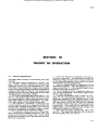
SECTIONIII
THEOR,Y
OF OPER,ATION
3-1.
CIRCIIIT DESCRIPTION
The Model 40?D consists of the following nine main
elements:
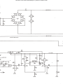
e. The high voltage transformer, rectifier, and
filter consist of silicon rectifiers CR1 through CR8,
capacitors C2 thru C11, and transformer T1. Taps
of the high voltage transformer winding which furnish
power to the full wave bridge rectifier are switched by
a section of the 0-500 volt control. This requires less
voltage drop and less power dissipation by the series
regulating tubes at low output voltages.
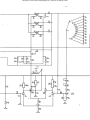
b. The series regulating tubes are tetrodes VL, V2,
and V3. The grids of these tubes are driven by the
error signal amplifier, which causes the tubes to regulate output voltage to prevent fluctuations. The regulated output appears at the cathodes of the tubes.
c. The precision, wirewound, constant-current
voltage sampling network is composed of S2B, R14
through R23, and R62 through R66. This network
determines the magnitude of the outpnt voltage, a sample
of which is compared to the reference voltage.
d. The reference voltage sources are V12 and R52.
Vl2 is operated at a constant current ol 2.2 ma, and
produces the reference voltage of 85.5 volts, which
should drift less than 0.45 mv per hour aIter the first
300 hours of operation.
e. The error detector is composed of Vl3 and associated components. Any difference between the
reference voltage and the output voltage is detected
by this differential amplifier, and a signal is produced
which tends to conect the difference.
f. The error signal amplifier is composed of V14 and
associated components. This tube amplifies the error
signal produced by "e."1 the amplified signal is then
applied to the grids of element "b. ".
g. The AC feedback loop is composed of capacitors
Cl3, C31 and resistor R72. This reduces ripple voltage
and AC output impedance.
h. The 250 volt auxiliary supply consists of CRll,
CR12, V8, V9, and associated components. Vg is the
differential amplifier for the auxiliary supply. The
heater current for V9 and V13 ls obtained from a filtered,
half-wave rectifier (CR13 and C36) which is regulated
by a transistor network (Q1, Q2, CR14 and associated
components). This improves the regulation of the
supply against large fluctuations in line voltage, and
stabilizes the operation of V9 and V13.
i. The screen grid supply includes CRg, CR10, R28,
and C15. This supply provides 340 volts for bias of
the screen grids of VL, V2, and V3.
3-l
Download v. www.rainers-elektronikpage.de ; gescannt von Rainer Fredel
Download v. www.rainers-elektronikpage.de ; gescannt von Rainer Fredel
40?D
sEcTtoN lv
'IIAI NTENANCE
4-1.
4-2.
INTRODUCTION
Very little maintenance, consisting primarily of occasional cleaning, tube replacement, and calibration,
ig necegsary for this power supply. A discussion of
troubleshooting and a tube voltage chart are presented
in paragraph 4-2. Calibration procedure and the equipment necessary are presented in paragraph 4-3..
SYMPTOM
TROUBLESHOOTING
The chart on the following pages lists various failures
and their possible causes and remedies. Tubes fail
more often than any other component, and should be
checked first.
If tubes are known to be good, voltage
and resistance measurements should be made.
POSSIBLE CAUSE
REMEDY
Qpen heater on tube or tubes.
Check all tubes to verify operation of heaters.
No high-voltage from supply.
Measure high voltage using a well insulated
probö.
Open R11, RU, Rl3, R65
or R66.
Measure and replace if necessary.
Shorted C31
Check and replace if necessary.
250V auxiliary supply out-oftolerance.
Turn BIAS control fully cloclnlise and measure
250V output. If not within *1$ replace R39
andforRll.
Also check C22, C31, R45, and
R46;
Otrt-of -calibration.
See paragraph 4-3.
lncorrect output over
part of range.
Out -of -tolerance resistor
in sampling network.
Turn ogtput to 500 volts and decrease one
position at a.time. The defective resistor is
in the läst pcisition in which the error was noted.
Small percentage error
over entire range.
Reference voltage drift.
Recalibrate per paragraph 4-3.
Output rises and follows
Iine voltage variations.
Defective Vl, V2, V3, V13,
or V14.
Replace if defective.
No output.
Incorrect output voltage
over entire range.
Figure 4-1.. TROUBLESHOOTING (sheet l of 2)
4-t
Download v. www.rainers-elektronikpage.de ; gescannt von Rainer Fredel
407D
SYMPTOM
L
'
REMEDY
POSSIBLE CAUSE
Oscillation.
O p e nC 1 3 , C 2 2 , C S L , o r
Check and replace if necessary.
Poor load regulation.
Weak V14.
Check and replace if necessary.
Poor line regulation.
Defective differential
amplifier(s)
Check differential amplifier circuits, beginning
with tubes, and replace defective component.
Excessive ripple.
D e f e e t i v eC 1 0 , C 11 , C 3 3 ,
or V14.
Check and replace if necessary.
Defective componentin
250V auxiliary supply.
Replace if defective.
Main output erratic
over entire range.
Defective R64 or R66.
Replace if defective.
Main output erratic
over part of range.
Same as incorrect output
over part of range.
See page 4-l
Main and auxiliary
output eratic.
Defective R39 or.R41
Measure and replace if necessary.
Poor stability.
Defective Vlz, Vl4.
Replace if defective.
Bias supply drift.
Check V5, C31, and C22. Replace if necessary.
No screen supply
voltage.
Open R28.
Before replacing R28, check C15. This resistor'
is designed to open in case of capacitor short to
protect the transformer winding and rectifiers.
No 250 VDC output
voltage.
Open R34.
Before replacing R34, check C20. This resistor,
also, is designed to open in case of c.apacitor
short to protect transformer witlding and
rectifie rs.
Fuse blows repeatedly..
Shorted C10 or Cll.
Check R3 and R4. If these resistors fail, it
will cause C10 and Cl1 to fail also. Replace
compoircnts as necessary.
l
I
c33.
Figure 4-1. ,.trROUBLESHoo:tfING (sheet 2 of.2)
4-2
Download v. www.rainers-elektronikpage.de ; gescannt von Rainer Fredel
407D
4-3. CALIBRATION
a". In order to calibrate the Model 407D, a voltmeter
having a minimum accuracy of 0. 1% should be used.
Any Fluke 800 series differential voltmeter is suitable.
b. Allow the instrument to operate for one-halI hour
minimum bef ore calibration.
c. Turn BIAS control fully clockwise and slide the
instrument out of its case to gain access to the calibration adjustments.
d. Connect the differential voltmeter to the BIAS
output terminals.
e. Adjust R40 so that voltmeter indicates -250 volts.
f.
Set the output voltage to zero volts.
g. Conrnct the differential voltmeter to the 0-555 volt
output terminals.
h. Set the MTR CKT switch to HV.
i.
Set S-2 to 500 volts.
Pin 1
Pin 2
Pin 3
vl, 80?
6.3V AC
at 500
850
443
v2, 807
6 . 3 VA C
at 500
850
v3, 807
6.3V AC
at 500
850
Symbol& Type
Pin 4
j.
Adjust R65 for 500 (*1.0) volts as indicated by the
diff erential voltm eter.
k. Set 52 to 0 volts.
l.
R€adjust R40 for 0 (*0.050) volts as irdicated by the
d,ff erential. voltmeter.
m. Repeat steps j thm l until both conditions can be
met.
4-4.
TUBE VOLTAGE CHART
This chart is to be used under the following conditions:
?. Line voltage is Lt5/280 vo!!s_, 50 - 60 cycles.'
b. No load is connected to the 40?D.
c. 0-500 switch is set to b00.
d. AII measurements are made with a VTVM from
negative 0-500 output post to specified terminal.
e. All voltages are DC unless otherwise noted.
Pin 5
Pin 6
Pin 7
Fin 8
Pin 9
Plate Cap
505 6 . 3 V A C
at 500
No
Pin
No
Pin
No
Pin
No
Pin
845
443
505 6 . 3 V A C
at 500
No
Pin
No
Pin
No
Pin
No
Pin
845
443
505
6 . 3 VA C
at -500
No
Pin
No
Pin
No
Pin
No
Pin
845
188
-13
No
Pin
No
Pin
No Cap
i
|
i
v8, 6AQ5
-13
0
v9, 12AX?
-96
-146
-159
12V DC
at -150
-96
- 161
- 157
See
Pin
4&5
No Cap i
vlo, 6Au8
-98
-96
0
6 . 3 VA C
at -150
-98
-96
-68
-L2
No Cap I
v12, 5651
- 163
-250
IC
-250
No
Pin
No
Pin
No Can
No Cap I
I
No Cap
v13, 124X7
-94
-162
v14, 6AU8
-96
-94
6.3 VAC
IC
188
-250
- 163
- 157
12V DC
at -150
-94
- 161
- 15?
See
Pin
4&5
0
6 . 3 VA C
at -150
-96
-94
-68
-61
Figure 4-2. TUBE VOLTAGE CHART
4-3
1
Download v. www.rainers-elektronikpage.de ; gescannt von Rainer Fredel
Download v. www.rainers-elektronikpage.de ; gescannt von Rainer Fredel
407D
sEcTtoNv
LIST OF REPTACEABTE
PAR,TS
5-1.
INTRODUCTION
The following list describes atl normally replaceable
parte in the Model 407D and 40?DR DC Power Supply.
Parts are identified on the list and on corresponding
illustrations by reference deeignations from the schematic diagram. Those parts which have no reförence
deeignation are ldentified by Fluke stock nunbers. The
40?DR is assembled dlfferently from the 40?D, and a
separate parts list is provided to show the difference.
5-2. HOWTOOBTAINPARTS
a. Most parts are standard components and can be
obtained loeatty. All parts manufactured, altered, or
REFERENCE
DESIGNATION
designed by Fluke are designated by an asterisk preceding the Fluke stock number. AII stmctural parts and
special parts shorld be purchased from your local Fluke
representative or from the.factory.
b. When orderlng parts,
always include:
(1) Reference designation, description and Fluke
stock number.
(2) Instrument model and serial number.
c. Most stmctural parts are not Iisted in the following
chart. To order theee, give complete description,
function, and location of part.
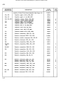
DESCRIPTION
Flnal Assenibly
(Cabkretmodel407D) (SeeFigure 5-1)
(Rack"model407DR) (SeeFigure 5-2)
FLUKE
sTocK No.
USE
CODE
*r 99158
*142968
*142968
Rectifter Prlnted Circutt Board Assembly
(SeeFigure 5-3
*121665
Front Panel Assembly (407D)
(SeeFlgure 5-4)
(407DR)
*140640
*142950
Amplifler Prlnted Clrcult Board Assembly
(SeeIigure 5-5)
't121673
Capacltor Board Assembty (SeeFieure 5-6)
*L2t723
c 1 0 ,c l l
Capacltor, Electrolyttc, 125 uf, -lO/+50%, 45OV
Capacltor, Electrolytic, S.d, -10/+50%, 500V
105098
1 0 5 11 4
cL2
Capacltor, ceramlc, 680pf, 10%, 500V
r05544
c13
Capacttor,' Oil, 4 uI, 20%, 900V
104893
c15
Capacltor, Electrolytic, 125 uf, -L0/50%, 450V
105098
105114
c20
Capacltor, Electrolyttc, 20 uf, -LÜ/+ffi%, 300Y
105106
c33
Capacltor, Electrolytlc, 16 uf, -L0/+50%, 450Y
105049
K
L
5-l
Download v. www.rainers-elektronikpage.de ; gescannt von Rainer Fredel
407D
REFERENCE
DESIGNATION
DESCRIPTION
USE
CODE
105171
c36
Capacitor, Electrolytic,
c38
Capacitor, Electrolytic, 1250 uf., +50/-LO%, 4V'
(Use with Honeywell Meters only)
166330
DS1
Lamp, Type 47
102855
F1
Fuse, Slo-BIo, 5A (407D only)
109215
Fuse Holder (407D only)
10388?
D
Fuse Holder (a07D only)
100107
A
R3, R4
Resistor, wirewound, 50K, 5%, 10W
112?63
R5, R6, R7
Resistor, composition, 220Q, lVk, L/XW
108191
R8, R9, R10
Resistor, composition, 1.5K, tffio, L/zW
108159
R11, R12, R13
Resistor, compositlon, 33Q, L0%, lW
1o9660
R35
Reslstor, composition, lM, 10%, lW
x)9793
R6?
Resistor, composition, 4.7Q, 5%, IW
109785
T1
Transformer,
Transformer,
V l , Y2, V3
Electron Tube Type 80?
Case Assemb\y
Foot, nylon
Foot, rubber
Handle
Line cord
5-2
2000 uf, -1.0/+100%, 25V
FLT]KE
STOCK NO.
Power (407D)
Power (40?DR)
*121?31
*142035
1166?4
*120386
*102921
1012ö3
10185?
r02822
Download v. www.rainers-elektronikpage.de ; gescannt von Rainer Fredel
40?D
121723
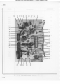
R5 Rl2 C12 R9 R6 Rl3 Rlo
c33
R67
cl0
R4
R3
cll
cl5
c36
Figure 5-1.
FINAL ASSEMBLY (Cabinet Model)
5-3
Download v. www.rainers-elektronikpage.de ; gescannt von Rainer Fredel
407D
cr0
cil
c20
cls
c33
c36
Rl3
Rl0
R4
R3
R35
-T-
rrf
DSI
Figure 5-2.
5-4
Fl
121723
FINAL ASSEMBLY (Rack Model)
Download v. www.rainers-elektronikpage.de ; gescannt von Rainer Fredel
407D
REFERENCE
DESIGNATION
DESCzuPTION
Rectifier Printed Circuit Board Assembly (See Figure 5-3)
FLUKE
STOCK NO.
* 121665
C2 thru C9, C17
Capacitor, ceramic, 1000 pf, 2070, 3000V
105635
c16
Capacitor, paper, 3300 pf, 20Vo, 600V
106559
CRl Thru CR13
Diode, silicon, 1N4822, 600 PIV, 1.0 Amp
11 2 3 8 3
cR14
Diode, Zener, 13V at 12 ma
1r 0 ? 2 6
Q1
Transistor,
germanium, 2Nl3?2
116129
Q2
Transistor,
germanium, RCA type 35487
116?07
R2
Resistor, wirewound, 4O, 57or 5W
tt2276
R28, R34
Resistor, composition, 10O, llEo, L/zW
108092
R29
R30
Resistor, composition, 220K, 1070. lW
F!,esistor, composition, 56K, LOflo,2W
Resistor, composition, 82K, lOEo, L/zW
109652
109991
108498
R31
Resistor, composition, 47K, llEo, L/zW
108480
R32
Resistor, composition, A'IOK, llflo, t/zW
108290
R36
Resistor, composition, 22K, 1070,lW
109470
R3?
Resistor, composition, 2.2K, l!7o, L/zW
108605
R71
Resistor, composition, 39K, lUflo, 2W
109983
v4, v5
Lamp, Neon, Type NE2E
Lamp, Neon, Type NE83
100347
1 7 01 6 7
Lamp, Neon, Type NE2E
100347
v6, v7
Heat sink
USE
CODE
z
AA
o
P
l
I
I
I
i
* 1 2 18 6 3
5-5
Download v. www.rainers-elektronikpage.de ; gescannt von Rainer Fredel
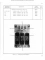
407D
c8
c9
c3
cR2
c2
p.
cRl
cR3
CRI
c1
c7
c5
c6
cR6
cR5
cRl0
R28
cn9
R29
R30
v5
V,f
t7
R3l
R32
c16
cR12
Q2
Ol
CRl3
CRl,t
Flgure 5-8. RECTIFIER PRINTED CIRCIIIT BOARDASST,IBLY
5-0
Download v. www.rainers-elektronikpage.de ; gescannt von Rainer Fredel
407D
FLUKE
REFERENCE
DESIGNATION
sTocK No.
Front Panel Assembly (See Figure 5-4)
(Model 407D)
(Model 407DR)
USE
CODE
*140640
*142950
c18
Capacitor, päDerr 0.047 nf, 20%, 1000V
Capacitor, paper mylar, 0.1 uf, 20%, 1000V
Capacitor, plastic, 0.25 uf, +Lffi, L200Y
10538?
105866
183616
c34
Capacitor, paper, 0.22üL, 20%, 400V
105304
c35
Capacitor, paper, 0.022 uf, 2(&, 600V
105411
c37
Capacitor, ceramic, 0.005 uf, 20%, 1000V
105650
F1
Fuse, 5A, SIo-BIo (a0?DR only)
109215
Fuse Holder (40?DR only)
103887
D
Fuse Holder (40?DR onfy)
10010?
A
J1, J4
Binding Post, Red
L429',16
J2, J3, J5
thru J10
Binding Post, Black
142984
Y
AB
G
Knob, 1 inch, w,/pointer
Knob, 13/16 inch, w,/bar
101287
*170050
s
Knob, 1'-1/2 inch; w,/pointer
Knob, 1 inch, wr/bar
1 0 1 3 11
*170035
s
M1
Meter, DC, 1 mllliampere
* 1111 7 9
B,24
Resistor, wirewound, 0.4?Q, L0%, L/zW
R25
Resistor, wire
R26, R?8
Resistor,
carborl film,
R62, R68
Reslstor,
vartable, wirewound, 50K, 10%, 3W
111690
R63
Resistor,
varlable, wirewound, 500Q, 10%, Z\il
111773
R69
Reslstor, carbon film,
R70
Resistor, carbon fllm, 90K, L%, LW
10?300
s1
Switch, toggle, SPST, 250V, 10 Amp
114850
s3
Snitch, rotary,
R
112888
* 115 5 3 5
600K, t%, 2W
10K, L%, L/zW
2 pole, 5 position
107417
107128
*tt4l28
*121889
Switch Assembly
s2
Swltch, rotary,
R14 thru
Resistor, wirewound, 45K, 0. 25%, t/2
Panel, front
R
3 pole, 11 positlon
*114?36
*112078
* 121558
5-7
Download v. www.rainers-elektronikpage.de ; gescannt von Rainer Fredel
407D
.-t0
)
:lt
-t0
MI
I
0.
0'tttt
i5
Jl
J2
t70035
J3
170035
r*
ID
ls
t".s
at!
g
lll
'F
oä-
,t,.
I
I
| 70050
H
J9
J8
G.,
r00r07 t70050
J3 J5
J6
J4 J2
Figure 5-4. FRONT PANEL ASSEMBLY (sheet I of 2)
5-8
r
J7
JI
Jr0
Download v. www.rainers-elektronikpage.de ; gescannt von Rainer Fredel
40?D
R68
c37
R73
s3
R26
R25
sl
Rt4
\\
Rl5
R62
R23
?22
R2r
R20
RI9
R63
ct8
c34
C3s R70 R69
Rt6 Rr7 Rl8
52
Rr9 R23 Rt7
R 2 rR 2 0 \ R 2 2 \ R l 8
5 2 R 1 6R 1 5R l 4
Figure 5-4. FRONT PANEL ASSEMBLY (sheet 2 of.2)
Download v. www.rainers-elektronikpage.de ; gescannt von Rainer Fredel
40?D
REFERENCE
DESIGNATION
DESCRIPTION
Amplifier Printed Circuit Board Assembly (SeeFigure 5-5)
FLT'KE
sTocK No.
USE
CODE
* 121673
czL, C32
Capacitor, paper, 0.22 uf, 20%, 400V
105304
c22, c27
Capacitor, paper, 0.1 uf, 20%, 400V
105312
c23, C25rC28
Capacitor, cerarnic, 300pf, 10%, 500V
Capacltor, ceramic, 680pf, 10%b00V
Capacitor, paper, 2200 pf, 20%1600V
Capacitor, paper 0.1 uf, 20%400V
Capacitor, plastic, 0.47 uf, 20%600V
105734
105544
105379
r05312
105494
c29
Capacitor, film, 0. 1 uf, 20%,200V
106435
c30
Capacitor, mica, 47 pf, 5S, 500V
105809
c
Capacitor, mica, 100pf, 1$, 500V
143370
B
c31
Capacitor, plastlc,0. 04uf, 201s,1600V
106344
R38
Resistor, composition, 130K, 5%, t/zV
108852
E3e
Resistor, wirewound, 265K, O.5%, 3/8W
R40
Resistor, variable, wirewound, lOK, 10%,2W
R41
Resistor, wirewound, 137K, t%, L/zW
R42
Resistor, composltion,330K, LO%,l/zW
t08274
R43, R50,
R54
Resistor, composition,680K, L0%,L/zW
108340
c
R43, R50
Resistor, composition,300K, 5%, l./zW
150193
B
R44
Resistor, composition, 1?K, t0%, l/zW
108530
c
Resistor, composiüonr.'8.2K, LO%,l/zW
10901?
B
R45
Resistor, composition, 8?K, L0%, L/2W
108498
R46
Resistor, corhposttion,47K, 5%, lW
150219
R4?
Reeistor, iarbon film, 28?K, L%, L/zW
Resistor, metal film, 133K, l%, L/zW
Resistor, carbonfllm, 135K, L%, L/zW
107?63
216168
10?201
R48
Resistor, composition, 100Q, LQ%,I/zW
108100
R49
Resigtbr, compesition; 330K, t0%, l/zW
L08274
c
Registor, composition,330K, 5%, L/zW
150201
B
R51, R53
Resistor, co.mposition,68K, L0%, \/2W
108332
R52
Resistor, wirewound, 76K, 0.5%, L/zW
* 111948
c24
c26
5-10
c
B
w
x
*LL2847
111 6 1 7 "
r112854
c
Y
B
Download v. www.rainers-elektronikpage.de ; gescannt von Rainer Fredel
407D
REFERENCE
DESIGI.IATION
DESCRIPTION
FLI]KE
STOCK NO.
USE
CODE
R54
Resistor, composition,270K, \Vo, L/zW-
150185
R55
Resistor, composition, 150K, lO%, t/zW
108167
R56
Resistor, composiüon,56K, LIV1,L/zW
L08472
c
Resistor, composition, 47K,,5%, L/zW
108?38
B
Resistor, composition, 150K, l0%, lW
109801
Resistor, composition,150K, 5%, LW
153122
B
Resistor,
Resistor,
Resistor,
Resistor,
Resistor,
150219
109629
107?63
zr6i68
10?201
T
U
Y
B
Resistor, composition,680K, LO%,l/zW.
108340
c
Resistor, composition,300K, 5%, L/zW
150193
B
Reslstor, composition,82K, LO%,l/zW
108498
c
Resistor, composition,39K, lO%, L/zW
108555
V
Resistor, composition,18K, L0%, L/zW
108183
U
R57
R58'
R59
R60
R61
cornposition, 47K, 5%, LW
composition, 68K, L|VoLW
depositedcarbon, 287K, l%| l/zW
metal film, L33K, t%, l/zW
depositedcarbon, L35If, L%, L/zW
R64
Resistor, wirewound,146.5K, 0,25%, lW
R65
Reslstor, variablel wirewound, 5K, L0%,2W
R66
P"72
Resistor, wirewound,?3.5K. 0.25%, l/zW
Resistor, composition, 330K*LM, t/g1t{
Tube, Beam Power, T1rye6AQ5
v8
V9,
v13
v10; vr4
v 11
vt2
B
c
*LL2243
111 5 8 3
*112094
L08274
116400
Tube, Dual Trlode;liTlpe 12AX7
11 5 9 5 6
Tube, Triode-Pentode,Type 6AU8
116426
H
Tube, Triode-Pentode, Type 6AW8
116434
J
Lamp, NeonGIow, Type NE2E
Lamp, NeonGlow, Type NE83
10034?
1?016?
P
Tube, Voltage Reference,TJrye5651-2
o
* 11 7 11 9
5 - 11
Download v. www.rainers-elektronikpage.de ; gescannt von Rainer Fredel
407D
R45
Vl I R49 R48 R38 V8
C30
R57 R56
c24
R46
vt4
Rrß
vl0
R55
c26
c25
V9
R50
R60
c29
c23
R54
c28
R,t4
R6l
R5l.
c3l
c27
c32
R53
vr3
R47
R59
R52
R72
R66
R64
R65
v12
R42 R4l
Figure 5-5. AMPLIFIER PRINTED CIRCUIT BOARD ASSEMBLY
5-t2
Download v. www.rainers-elektronikpage.de ; gescannt von Rainer Fredel
. 0 7I )
REFERENCE
DESIGNATION
DESCRIPTION
C a pa c i t o r B o a r d A s s e m b l y ( S e eF i g u r e 5 - 6 )
FLUKE
STOCK NO.
*L2r723
c1, c14, c19
C a pa c i t o r, p l a s t i c , 0 . 0 4 7 u f , 2 0 q , , 1 6 0 0 V
106344
R1
R e s i s t o r, c o m p o s i t i o n , 1 0 0 4 . 1 0 q 0 ,L / 2 W
r08100
P.27
R e s i s t o r, c o m p o s i t i o n , 3 3 0 4 . I } , J , , ,L / 2 W
108589
R33
R e s i s t o r, c o m p o s i t i o n , 1 2 0 f , ) ,L \ q o , I / z W
r08696
USI:l
CC)I)Ti
tr
R27
cl4
Figure 5-6.
C A PA C I TO R B O A R D A S S E M B LY
5-13
Download v. www.rainers-elektronikpage.de ; gescannt von Rainer Fredel
40?D
5-3.
USE CODE EFFECTTVITY
The customer can determine the effectivi.ty of all replaceable parts by use of the following use code effectivity list. All parts with no code are used on all instruments with serial numbers 123 and on.
USE
CODE
No
Code
EFFECTIVITY
Model 407D serial number 123 and on
Model 407DR serial number 123 and on
A
Model 407D serial number 651 and on
Model 407DR serial number 319 and on
B
Model 407D serial number 616 thru 624,
626, 628, 630, 631, 633 thru 63?, 640, 641,
643, 644, 648, 650 and on
Model 40?DR serial number 319 and on
C
Model 407D serial number 123 thru 615,
625, 627, 629, 632, 639, 639, 642, 645, 646,
647, 649
Model 407DR serial number t23 thru 318
R
Model 407D serial number 123 thru 1005
Model 407DR serial number 123 thru 559
Model 40?D serial number 1006 and on
Model 407DR serial number 560 and on
T
Model 407D serial number 123 tlru 975
Model 40?DR serial number 123 thru 559
U
Model 40?D serial number 9?6 and on
Model 40?DR serial number 560 and on
v
Model 40?D serial number 616 thru 624,
626, 628, 630, 631, 633 thru 63?, 640,
641, 643, 644, 648, 650 thru 9?5.
Model 40?DR serial number 319 thru 559
w
Model 407D serial number 123 thru l03b
Model 40?DR serial number 123 thru b84
x
Model 40?D serial number 1036 and on
Model 407DR serial number 58b and on
Model 40?D serial number 12?9 and on
Model 407DR serial number 892 and on
D
Model 407D serial number 123 tltru 650
Model 407DR serial number 123 thru 318
z
Model407D seriat number 396 thru 1348
Model 40?DR serial number 286 thru 1011
E
Model 407D serial number 396 and on
Model 40?DR serial number 286 and on
AA
Model 40?D serial number 1349 and on
Model 40?DR serial number 1012 and on
F
Model 40?D serial number 123 thru 395
Model 40?DR serial number 123 thnr 285
AB
Model 407D serial number 1379 and on
Model40TDR serial number 1032 and on
G
Model 40?D serial number 186 and on
Model 407DR serial number 191 and on
H
Model 407D serial number 123 thru 7?0
Model 407DR serial number 123 thru 373
J
Modet 407D serial number ?71 and on
Model 40?DR serial number 374 and on
K
Model 40?D serial number 396 thru 936
Model 407DR serial number 286 thru 534
L
Model 40?D serial number 123 thru 395, 93?
and on
Model 407DR serial number 123 thru 285, 535
and on
M
Model 407D serial number 123 thru 830
Model 407DR serial number 123 thru 463
N
Model 407D serial number 831 and on
Model 407DR serial number 464 and on
o
Model 40?D serial number 123 thru 9?5
Modet 40?DR serial number 123 thru 533
P
Model 407D serial number 9?6 and on
Model 407DR serial number 534 and on
5-14
Download v. www.rainers-elektronikpage.de ; gescannt von Rainer Fredel
I-,i s t <rf ß-arct<lr..y A ut lrtrr.i ztrcl S ( r r v i c e
ARIZONA
MARYLAND
( l e n t e r. s
oHto
PHOENIX
KENSINGTON
CLEVELAND
ArizonaStandardsIaboratorv
4430N. l9th Ave.
Tel. (602)264-935r
ElectronicMarketingAssociates
I l50l Huff Court
Tel. (301) 946-0300
TWX. 710-825-9645
HoneywellMetrologyService
l 0 0 l E . 5 5 t hs t .
Te l . ( 2 16 ) 8 8 t - 0 3 0 0
FAIRBORN
CALIFORNIA
MASSACHUSETTS
LOSANGELES
ARLINGTON
InstrumentSpecialists,
Inc.
P. O. Box 39908
2870Los FelizPlace
Tel.(213)66s-5181
TWX:910-321-3914
Instrument Representatives,
Inc.
I 046 Massachusetts
Ave.
Tel. (617) 646-1034
ALBUQUERQUE
COLORADO
BallBrothersResearch
Corp.
Standardization
laboratorv
Tel. (303) 444-53Oo
TWX:910-940-3241
TEXAS
GARLAND
N E WM E X I C O
BOULDER
HoneywellMetrologyServicc
600 EastDayton Dr.
Te l . ( 5 I 3 ) 8 7 8 - 2 ss I
EG & G Standardsand Calibration
laboratory
P. O. Box 4339, StationA
933 BradburyDrive S. E.
Tel. (505) 8424084
Tucker ElectronicsCompany
326 Kirby Street
Tet. Qta) 212-3404
HOUSTON
LinearStandardsl.aboratory
8207 Millet
Tel. (713) 923-2796
N E WY O R K
FLORIDA
PLEASANTVILLE
ORLANDO
SBM Associates
28 Hobby Street
BCSAssociates,
Inc.
P. O. Box6578
940N. FernCreekAve.
Tel.(305)42s-2764
TWX.810-850-0185
Tel.(9la) 769.18rr
TWX.710-s72-2193
HAWAI I
HONOLULU
IndustrialElectronics
P. O. Box135
646QueenStreet
Tel. (808)s06-09s
TWX.63238
ROCHESTER
SBMAssociates
800 LindenAve.
Tel.(716)381-8330
TWX.510-2s3-6145
UTAH
SALTLAKECITY
Stabro [aboratory
23 KensingtonAve.
Te l . ( 8 0 1 )4 6 7 - 8 o t l
CANADA
TORONTO
Allen Crawford AssociatesLtd.
65 Martin RossAve.
Downsview,Ontario
Tel. (al6) 636-4910
TWX. 610-492-2119
Download v. www.rainers-elektronikpage.de ; gescannt von Rainer Fredel
INTERNATIONAL
THE NETHERLANDS
I.'NITED KINGDOM
FlukeNetherlandN. V.
P. O. Box 5053
Tilburg,The Netherlands
FlukeInternationalCorp
P. O. Box 102
Watford-Herts,
England
For informationregardingservicecentersin other foreignlocations,contactthe nearestSales
in your area.
and ServiceRepresentative
Download v. www.rainers-elektronikpage.de ; gescannt von Rainer Fredel
W A R R A N TY
The JOHN FLUKE MFG. CO. , INC. warrants each instrument manufactured by them
to be free from defects in material and workmanship. Their obligation under this
Warranty is limited to servicing or adjusting an instrument returned to the factory
for that purpose, and to making good at the factory any part or parts thereof ; except
tubes, fuses, choppers and batteries, which shall, within one year after making delivery to the original purchaser, be returnedby the original purchaser with transportation charges prepaid, andwhich upon their examination shall disclose to their sat'isfaction to have been thus defective. If the fault ha^sbeen caused by misuse or abnormal
conditions of operation, repairs will be billed at a nominal cost. Irx this case, an
estimate will be submitted before work is started, if requested.
If any fault develops, the following steps should be taken.
1. Notify the John Fluke Mfg. Co. , Inc. , giving full details of the difficulty,
and include the Model number, type number, and serial number. On
receipt of this information, service data or shipping instructions will
be forwarded to you.
2. On receipt of the shipping instructions, forward the instrument prepaid,
and repairs wiII be made at the factory. If requested, an estimate of the
charges will be made before the work begins, provided the instrument
is not covered by the Warranty.
SHIPPING
AII shipments of John Fluke Mfg. Co. , Inc. instruments should be made via Railway
Express prepaid. The instrument should be shipped in the original packing carton;
or if it is not available, use any suitable container that is rigid. If a substitute container is used, the instrumert should be wrapped in paper and surrounded with at least
four inches of excelsior or similar shock-absorbing material.
CLAIM FOR DAMAGE IN SHIPMENT
The instrumext should be thoroughly inspected immediately upon receipt. AII material
in the container should be checked against the enclosed packing list. The manufacturer will not be responsible for shortages against the packing sheet unless notified
immediately. If the instrument fails to operate properly, or is damaged in any way,
A full report of the damage should be oba claim should be filed with the carrier.
tained by the claim agent, and this report should be forwarded to John Fluke Mfg.
Co., Inc. Upon receipt of this report you will be advised of the disposition of the
equipment for repair or replacement. Include the model number, type number, and
serial number when referring to this instrument for any reason.
The John Fluke Mfg. Co. , Inc. wiII be happy to answer all application questions which
wiII enhance your use of this irstrument. Please address your requests to:
JOHN FLUKE MFG. CO. , INC. , P. O. BOX 7428, SEATTLE 33, WASHINGTON
Download v. www.rainers-elektronikpage.de ; gescannt von Rainer Fredel
Download v. www.rainers-elektronikpage.de ; gescannt von Rainer Fredel
FI
REMO1€
For 40?D ser 396 to 615 plus 625, 627, 629, 632
6 3 8 , 6 4 2 , 6 4 5 , 6 4 6 , 6 4 7& 6 4 9
4 0 7 D Rs e r 2 8 6 t o 3 1 8
C23, C25, & C28
C30
R43. R50, R54 & R60
R44
R4?, & R59
R56
ROf
were 300pf
was 4?pf
were 680K
was 15K
were 287K
was 56K
was 82K
were NE2E
was 0.1u1
j
[vMA€-rs
was 39K
USEO
Rr-R73
cr-ctrl
e
was 4?K
R6l
cRl-cRl4
v1-vr4
r,
F1
T1
Qr-Q2
D61
M1
* ctg
T o47
535vac 3...
FOR4O7DSER.NO. 1279AND ON
A N D 4 O 7 DS
RE R N
. O.892AND ON
r'ALU€15 ]33K
5 € R .N O S . N O T I N D I C AT E8DY '
VALUTWAS I35K
4 0 7 Ds e r 3 9 6t h r u 1 0 3 5
40?DRser 286 thru 584
40?D ser 616 thru 624, 626, 628, 629
thru 631, 633 thru 63?, 6 3 9t h r u 6 4 1 , 6 4 3 ,
644, 648 & 650 thru 9?5
407DRser 319 thru 559
ALt FLAGNOTTSWITH
AR€
SAMTNUMBER
CONNTCTED
FOR 4O7DR. ALL OUTPUTS
O N F R O N T PA N E L A R EA L S O
A r ' A I L A B LT AT R E A RT € R M I N A L
S T R I P. P R O V I S I O N F O R R E MOTE CONIROT OF AC IS AL5O
A ! A I TA B L E O N R E A R PA N E L O F
40lDR
40?D ser 396 thru 9?5
4 0 ? D Rs e ! 2 8 6 t h r u 5 3 3
R58
cRrz
C H A S S IGSR O U N D
>
4 0 7 Ds e r 1 2 3t h r u 9 ? 5
4 0 ? D Rs e r 1 2 3t h r u 5 5 9
cRil
R28
rO
A L LD C V O TA C E A
S R EM E A S U R E D
FNOMN€GATIVI0-555VOLT
OUTPUTPOSTWITHO-5OOV
slvlTcH oN 500,I l5vAc LINE
/ O LTA C EA N D N O L O A D
were 1.25ui
C26
CR|O
O T H E R W IISNED I C AT E D :
U N LT S S
R E S I S TA N CAERS€I N O H M S .
C A PA C I TA N CA
€R
S EI N M I C R O .
FARAD5
40?Dser 396 thru 936
4 0 ? D Rs e r 2 8 6t h r u 5 3 4
v4&v5
cRg
2.]OVOI,TOP€RATION:
FROMAC TO AD
PLACE
JUMPER
O N T I . C H GF I T O Z A , S L O W - B t O
were6AU8
Cf 0 & Cll
AC
PLACE
FROMA8 TO AD
JUMPER
A N D F R O MA C T O A E O N T I
40?D ser 123thru 7?0
40?DRser 286 thru 534
V10& V14
cl
.o41
POWER
(t
F O R4 0 7 Ds f R . N O . l 2 l 9 A N D O N
AND 4O7DR
SER.NO. 892AND ON
VALUTlS 0. I uf
A L LO T H T R
S E RN
. O S . T H EVAT U I
WAS0.047u{
FOk
.lo/ i,
I3+8
1 HRU
4f.ibI{
f ltlt',
sLl.i
töt\
SLk
AND
r t R
No
t{l)
@ c.}e u5E (rrrF HoAt€Yw€LL
m E r E i 5 O r v Ly
@ ror {o? o sEe xo.t?1q
ArD o^,,4orDR SgQtuo.
to3) Atrr/ 0rt, clg eHG'D
fO 0.25
u{
FRoMo'tuf
osl
POWERON
INDICATOR
R34
lo
,ll3
Download v. www.rainers-elektronikpage.de ; gescannt von Rainer Fredel
Download v. www.rainers-elektronikpage.de ; gescannt von Rainer Fredel
l]Rt2
53
ltt* @
Rt2
4?OK
R64
r46500
R65
5I(
R65
73500
-250VDO
0 VOLT
ADJUST
Download v. www.rainers-elektronikpage.de ; gescannt von Rainer Fredel
r
Rt4
45K
Rt5
45K
Rt6
45K
Rr7
45X
Rt8
45K
Rt9
45K
R20
45X
R2l
45K
R22
45K
R23
a5K
-25VDC
atAs
OUTPUT
R64
r46500
R65
5I(
-250VOC
BrAS
OU'PUT
0 VOL1
ADJUST
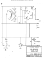
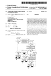
FUNCTIONAL
S C H E M AT I C
R66
?3300
HIGHRESOLUTION
DC POWERSUPPLY
MODEL4O7D
4O7D
4o7 DP
Ftrrel
:
SER. No.33c;€ON
SER. NO. aAG;eON
JoHN FLTTKEMFc. cO.,,tNC.
P.O. 8or 7428
Srorrh, tflcshington98133