1
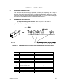
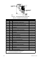
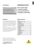
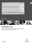
OPERATOR’S MANUAL HSM SERIES 1000 AND 1500 WATT SWITCHING POWER SUPPLY VOLTAGE/CURRENT-STABILIZED DC SOURCE MODEL KEPCO INC. An ISO 9001 Company. HSM SERIES POWER SUPPLY IMPORTANT NOTES: 1) This manual is valid for the following Model and associated serial numbers: MODEL SERIAL NO. REV. NO. 2) A Change Page may be included at the end of the manual. All applicable changes and revision number changes are documented with reference to the equipment serial numbers. Before using this Instruction Manual, check your equipment serial number to identify your model. If in doubt, contact your nearest Kepco Representative, or the Kepco Documentation Office in New York, (718) 461-7000, requesting the correct revision for your particular model and serial number. 3) The contents of this manual are protected by copyright. Reproduction of any part can be made only with the specific written permission of Kepco, Inc. Data subject to change without notice. ©2015, KEPCO, INC P/N 243-0850c KEPCO® THE POWER SUPPLIER™ KEPCO, INC. 131-38 SANFORD AVENUE FLUSHING, NY. 11355 U.S.A. TEL (718) 461-7000 FAX (718) 767-1102 email: [email protected] World Wide Web: http://www.kepcopower.com TABLE OF CONTENTS SECTION PAGE SECTION 1 - INTRODUCTION 1.1 1.2 1.3 1.4 1.4.1 1.4.2 1.4.3 1.4.4 1.4.5 1.4.6 1.4.7 1.4.8 1.4.9 1.4.10 1.5 1.5.1 1.6 Scope of Manual ..................................................................................................................................... 1-1 General Description................................................................................................................................. 1-1 Specifications .......................................................................................................................................... 1-1 Miscellaneous Features .......................................................................................................................... 1-5 Control/programming ......................................................................................................................... 1-5 Status Flags:...................................................................................................................................... 1-5 Setpoint Monitors:.............................................................................................................................. 1-5 Remote Error Sensing: ...................................................................................................................... 1-5 Load Sharing: .................................................................................................................................... 1-5 Load Monitor:..................................................................................................................................... 1-5 Auxiliary Supply: ................................................................................................................................ 1-5 Overcurrent/undervoltage Protection:................................................................................................ 1-5 Current Walk-in:................................................................................................................................. 1-5 Remote Reset:................................................................................................................................... 1-5 Options .................................................................................................................................................... 1-6 Battery Charger (B Suffix):................................................................................................................. 1-6 Accessories ............................................................................................................................................. 1-6 SECTION 2 - INSTALLATION 2.1 2.2 2.3 2.4 2.5 2.6 2.7 2.7.1 2.7.2 2.7.3 2.7.4 2.7.5 2.7.5.1 2.7.5.2 2.7.5.3 2.7.5.4 2.7.6 2.7.7 Unpacking and Inspection ....................................................................................................................... 2-1 Terminations and Controls ...................................................................................................................... 2-1 Source Power Requirements .................................................................................................................. 2-3 Cooling .................................................................................................................................................... 2-3 Preliminary Operational Check................................................................................................................ 2-3 Installation ............................................................................................................................................... 2-4 Wiring Instructions................................................................................................................................... 2-4 Safety Grounding............................................................................................................................... 2-4 Source Power Connections ............................................................................................................... 2-4 D-C Output Grounding....................................................................................................................... 2-5 Power Supply/Load Interface............................................................................................................. 2-5 Load Connection - General................................................................................................................ 2-6 Load Connection - Method I (Local Error Sensing)...................................................................... 2-7 Load Connection - Method II (Remote Error Sensing)................................................................. 2-8 Load Connection - Method III (Series Connection)...................................................................... 2-9 Load Connection - Method IV (Parallel/Redundant Operation) ................................................... 2-10 Load Sharing ..................................................................................................................................... 2-11 Signal Connections............................................................................................................................ 2-12 SECTION 3 - OPERATING INSTRUCTIONS 3.1 3.2 3.3 3.4 3.5 3.6 3.7 3.8 3.9 3.10 3.11 3.12 Operating Configuration .......................................................................................................................... 3-1 Remote Error Sense................................................................................................................................ 3-1 Output Voltage Programming.................................................................................................................. 3-1 Output Voltage Range............................................................................................................................. 3-2 Current Limit Programming ..................................................................................................................... 3-2 Current Limit Programming Range.......................................................................................................... 3-3 Setpoint Monitors .................................................................................................................................... 3-3 Overvoltage Protection Adjustment ......................................................................................................... 3-4 Current Limit Characteristic ..................................................................................................................... 3-5 Current Walk-in Circuit ............................................................................................................................ 3-6 5VAUX Floating Supply ........................................................................................................................... 3-6 Remote Inhibit/Remote Reset Controls................................................................................................... 3-7 HSM OPR 082115 i TABLE OF CONTENTS SECTION 3.13 3.14 3.14.1 3.14.2 3.14.3 3.14.4 PAGE Module Current Monitor .......................................................................................................................... Status Flags............................................................................................................................................ Source Power Status Flags .............................................................................................................. OUTPUT Status Flags ...................................................................................................................... OVERTEMP Status Flags................................................................................................................. FANFAIL Status Flags ...................................................................................................................... 3-7 3-8 3-8 3-9 3-10 3-10 LIST OF FIGURES FIGURE 1-1 1-2 1-3 2-1 2-2 2-3 2-4 2-5 2-6 3-1 3-2 3-3 3-4 3-5 3-6 PAGE HSM Series Power Supply ........................................................................................................................... iv Temperature Derating ................................................................................................................................ 1-3 Outline Drawing.......................................................................................................................................... 1-4 HSM Series Output Controls and Configuration Switch Functions ............................................................ 2-1 HSM Series Rear Panel Connections ........................................................................................................ 2-2 Load Connection - Method I (Local Error Sensing) .................................................................................... 2-7 Load Connection - Method II (Remote Error Sensing) ............................................................................... 2-8 Load Connection - Method III (Series Connection) .................................................................................... 2-9 Load Connection - Method IV (Parallel/Redundant Operation wit Hot Swap ............................................. 2-10 External Resistance Programming of Output Voltage................................................................................ 3-2 External Voltage Programming of Output Voltage ..................................................................................... 3-2 External Voltage Programming of Current Limit......................................................................................... 3-3 Current Walk-In Characteristic ................................................................................................................... 3-6 Remote Inhibit Control Operation............................................................................................................... 3-7 Timing Diagram for POWER and DCFAIL Status ...................................................................................... 3-9 LIST OF TABLES TABLE 1-1 1-2 1-3 2-1 2-2 3-1 3-2 ii PAGE Model Parameters ...................................................................................................................................... 1-1 General SpecificationS ............................................................................................................................... 1-2 Accessories ................................................................................................................................................ 1-6 Configuration Controls ................................................................................................................................ 2-1 I/O Connector Pin Assignments ................................................................................................................. 2-2 Status Flags ............................................................................................................................................... 3-8 Fault Detector Operation ............................................................................................................................ 3-10 HSM OPR 082115 FIGURE 1-1. HSM SERIES POWER SUPPLY (iii Blank)/iv HSMSERIES OPR 082115 SECTION I - INTRODUCTION 1.1 SCOPE OF MANUAL This manual contains instructions for the installation and operation of the HSM series of voltage and current stabilized d-c power supplies manufactured by Kepco, Inc., Flushing, New York, U.S.A. 1.2 GENERAL DESCRIPTION The HSM power supply is basically a voltage and current stabilized d-c source with a relatively sharp crossover between voltage and current mode operation. This permits HSMs to be used both as conventional regulated voltage sources and in applications such as battery chargers, where automatic crossover between constant voltage and constant current operation is required. HSM power supplies are supplied in a single mechanical size and are nominally rated at either 1000 or 1500 watts of output power. HSM 1000 watt power supplies are designed to operate over the universal a-c power mains voltage range of 90-277V (47-63Hz), with operation from 125-420V d-c also available. HSM 1500 watt products provide full power over the a-c mains range of 180-277V a-c, with output power derating linearly to 1000 watts as a-c mains voltage drops from 180 to 90V a-c. Active power factor correction circuitry limits source current harmonics to negligible levels, significantly improving source power utilization. Cooling is provided via an internal d-c fan. The HSM permits adjustment of both output voltage (VO) and current limit (IMAX), either by internal (pot) or external (resistance or voltage) methods; programming method is selected via DIP switches accessed through the top of the unit. Independent circuitry provides protection against overvoltage, overcurrent and overtemperature failures; fault detection circuitry monitors performance of the output and critical internal functions, providing both visual and electrical indicators. A switch-selectable “current walk-in” circuit and optional float/equalize functions enhance the performance of HSM power supplies for such applications as battery chargers The HSM power supply is designed for fixed installation applications where the load connections are hard-wired to the power supply. Forced current sharing and unique internal fault detection circuitry permits straight paralleling in redundant power applications with or without output blocking diodes. Kepco RA 58 (or similar) rack adapters are available for EIA standard rack mounting. For applications requiring plug-in or hot-swap power supply modules refer to Kepco HSP Series power supplies. 1.3 SPECIFICATIONS Table 1-1 below indicates specifications for parameters that vary for different HSM models; Table 1-2 lists general specifications that apply to all HSM models. TABLE 1-1. MODEL PARAMETERS OUTPUT VOLTAGE (Volts) 1500 Watts 1000 Watts MODEL OVP SETTING (Volts) OUTPUT CURRENT (Amps) RIPPLE (mV p-p) NOISE (mV p-p) EFFICIENCY (Percent) (See Note 1.) Nominal (Factory Set) Adjustment Range Factory Setpoint 50 ° C 60 ° C 71 ° C Source max Switching max (Spike) 20MHz 100% Load 115V a-c HSM 3.3-230 HSM 5-200 3.3 5 0.7-3.6 1.0-5.5 4.29 6.5 230 200 173 150 105 95 20 20 30 30 100 100 71 72 HSM 12-84 12 2.4-13.2 15.6 84 63 40 20 40 120 73 HSM 15-66 15 3.0-16.5 19.5 66 49.5 31.4 20 40 150 76 HSM 24-42 24 4.8-26.4 31.2 42 31.5 20 20 60 240 77 HSM 28-36 28 5.6-30.8 36.4 36 27 17 20 60 280 78 HSM 48-21 48 9.6-59.2 62.4 21 16 10 20 60 480 80 HSM 24-60 24 4.8-26.4 31.2 60 45 28.6 20 60 120 77 HSM 28-53 28 5.6-30.8 36.4 53 39.8 25.2 20 60 140 78 HSM 48-30 48 9.6-59.2 62.4 30 22.5 14.3 20 60 240 80 1. “R” Model efficiency is typically 2-3% lower. HSMSERIES OPR 082115 1-1 TABLE 1-2. GENERAL SPECIFICATIONS CHARACTERISTIC REQUIREMENT CHARACTERISTIC REQUIREMENT SOURCE INPUT Source Voltage AC: Single-Phase, 1500W 1000W Nominal: 100-250V rms 200-250V rms Range: 90-277Vrms 180-277V rms DC: 125-420V d-c (polarity insensitive) † Brownout Voltage 1000W:75 V a-c typ. 1500W:150 V a-c typ. Source Frequency 47-440 Hz (Frequencies in excess of 63Hz will cause leakage current to exceed limits specified below) 120V a-c 11A rms max 240V a-c 1000W: 5.5A rms max 1500W: 8.0A rms max Current Power Factor Inrush Current Efficiency Withstand Voltage (See Note 2) OUTPUT/LOAD Nominal Voltage See Table 1-1. Rated Current See Table 1-1. Minimum Output Current Output Voltage Range Regulation Error Start-up Time 3000V rms Input to Output 1500V rms Input to Case 500V d-c Output to Case Safety Agency Approvals <1.0mA @ 230V a-c, 47-63Hz UL Recognized (SELV) UL 1950 / UL1459 Para. 35A.1 CSA Certified (SELV) CSA 22.2 No. 234-M90 (Level 5) Radiated RF (Ampl. Mod.) (ENV50140) 10V/m, 80-1000MHz Immunity (See Note 3) Electrostatic Discharge (EN 61000-4-2) Contact: 4KV, Air: 8KV Conducted RF (ENV50141) 10Vrms, 0.15-80MHz Electrical Fast Transient (EN 61000-4-4) 2KV, Tr/Th = 8/20µs Input Surge (EN 61000-4-5) Comm. Mode: 2KV; Diff. Mode: 2KV Conducted RF (CISPR 22) Class A Limits, 0.15-30MHz Emissions Current Harmonics (EN 61000-3-2) 0-2KHz, any source/load condition) 0.1% from 5% to 100% of rated load Temperature Effect 0.02%/°C, 0°C<TA<50°C Time Effect (Drift) 0.1%/24 hr period after 30 min. warmup 0.3% See Table 1-1. 1 sec maximum at rated output current Output Hold-up Time 5 msec following power loss indication >27 msec total time prior to loss of output regulation Turn-on/Turn-off Overshoot Load Transient Response (25% load transient, 2A/µsec rise/fall time) Output Polarity Within load transient response envelope 3% of nominal output voltage Maximum excursion 100msec return to within 1% of Recovery time set voltage All outputs are floating and can be referenced as required by the user at up to ±500V d-c. Radiated RF (Pulse Mod.) (ENV50204) (Pulse) 10V/m, 900MHz Magnetic Field (EN 61000-4-8) 30A/m, 50Hz Load Effect 21.5 msec transparent power loss (no indication) <0.50mA @ 115V a-c, 47-63Hz Leakage Current 0.1% over full source voltage range Combined Effect Ripple and Noise See Table 1-1. See Table 1-1. Source Effect 0.99 typical; 0.96 minimum for all source conditions and loads from 25% to 100% of rated load. 75A max 2% of rated load (lower output conditions may result in increased output ripple and increased transient response recovery time). PROTECTION Input Fusing Internal fuse, hot line only (not operator serviceable - refer to Service Manual). Low A-C Protection HSM Power supplies will self-protect, no fixed limit. Overvoltage Protection Latched shutdown if output voltage exceeds user-selected limit (see Operating Instructions, PAR. 3.8) (see Note 4). Overcurrent Protection Constant current limiting (optional undervoltage-activated latched shutdown (see Operating Instructions, PAR. 3.9) (see Note 4). Overtemperature Protection Thermostat shutdown with hysteretic recovery and automatic restart. NOTES:1. Safety Agency approvals for a-c input only 2. 25o C, 65% RH 3. Per EN 50082-2, Acceptance Criteria A 4. Latched shutdown requires that source power be cycled for restart (optional restart by cycling REMOTE ON/OFF control signal); see Operating Instructions, PAR. 3.12. 1-2 HSMSERIES OPR 082115 TABLE 1-2. GENERAL SPECIFICATIONS (CONTINUED) CHARACTERISTIC REQUIREMENT CHARACTERISTIC SIGNAL AND CONTROL 3.3V & 5V Models Remote Error Sensing All other Models Remote On/Off Control REQUIREMENT ENVIRONMENT 0.25V per wire 0.8V per wire Operating Temperature Range Isolated TTL-compatible signal; either logic high or logic low will disable output. Storage 0 to 50° C: rated load; 50° C to 71° C: derate by 2.5%/° C, see Figure 1-2.) -40 to +85° C Load Sharing Within 5% of load when connected via load sharing wire (see PAR. 2.7.6). Cooling Internal d-c fan (inlet, exhaust as indicated in Figure 1-3). Load Monitor 0-5V analog signal proportional to output load current; 5V at 100% of rated load. Humidity 0-95% RH (non-condensing), Operating and Storage. POWER Status Flags (Form C dry relay contacts) (See PAR. 3.14.) (See Notes 5 and 7.) OUTPUT OVERTEMP FAN FAIL Auxiliary Voltage (Isolated) Voltage Set Programming Mode selected by internal switches (See Note 6.) (See PAR. 3.3.) Current Limit Programming Indicates low source voltage; signal asserted a minimum of 5 msec prior to loss of output voltage. Indicates HSM Power Supply in normal operating mode. Indicates HSM Power Supply in overtemperature shutdown. Indicates failure of internal cooling fan. 4.75-5.25V d-c output, 0 - 100mA, parallelable, output isolated (500 V d-c), Input isolated (SELV) (See Operating Instructions, PAR. 3.11). Internal Multiturn pot External 1 Resistance: 0-50K External 2 0-10V, 500µA max Internal Multiturn pot External 0-10V, 500µA max Shock Non-operating, 20g, 11msec 50%, half sine, 3 axes, 3 shocks each axis 5-10Hz 10mm, double amplitude 10-55Hz 2g Vibration Altitude Sea level to 10,000 feet PHYSICAL Dimensions See Figure 1-3. Weight 16 lbs. (7.3Kg) Source Connections 3-pin power entry module (compatible with IEC 320/C19 molded line cord plug. Load Connection Two bus bars (+ and -)1.0 x 0.125 inch, copper w/bright nickel finish Signal Connection 37-pin D-subminiature connector (male) NOTES 5: Status flags are isolated and operate independently. 6: The POWER/DCFAIL fault detector window tracks programmed output voltage, however, the overvoltage protection trip point remains unaffected. 7. Form C contacts: rated from 30V d-c/1A to 60V d-c/0.3A. FIGURE 1-1. FIGURE 1-2. HSMSERIES OPR 082115 TEMPERATURE DERATING 1-3 FIGURE 1-3. 1-4 OUTLINE DRAWING HSMSERIES OPR 082115 1.4 MISCELLANEOUS FEATURES 1.4.1 CONTROL/PROGRAMMING a)VOLTAGE CHANNEL: Output voltage is controlled continuously throughout the specified adjustment range via a 10-turn potentiometer accessed through the top cover. External control can be exercised either by resistance or by control voltage (see PAR.s 3.3 and 3.4). b) CURRENT CHANNEL: Output current is controlled continuously throughout the specified adjustment range via a 10-turn potentiometer accessed through the top cover. External control can be exercised by control voltage (see PAR.s 3.5 and 3.6). c) OVERVOLTAGE LEVEL: The output voltage level at which the overvoltage protection latch is activated may be adjusted locally via a 10-turn potentiometer accessed through the top cover (see PAR. 3.8). d) REMOTE INHIBIT: Operation of the output regulator can be inhibited remotely via either one of two TTL-level control lines, RC1 and RC2. Both of these signals are isolated from both the input and output, allowing single-point control of several power supplies operating at different potentials. Both positive and negative logic are supported (see PAR. 3.12). 1.4.2 STATUS FLAGS: Four sets of Form C dry relay contacts (3 wires each) are provided at the I/O connector which duplicate the front panel status indicator functions (see PAR. 3.14). 1.4.3 SETPOINT MONITORS: Analog voltage signals which display programmed output voltage and current limit values. These signals are available at the I/O connector (VSET and ISET). Signals are referenced to negative error sense (see PAR. 3.7). 1.4.4 REMOTE ERROR SENSING: Separate voltage sensing connections permit 4-wire connection to load. Will compensate for static load effects due to power lead d-c resistance (DCR) up to specified maximum voltage drop per load lead at maximum specified output voltage (see PAR. 3.2). 1.4.5 LOAD SHARING: Bidirectional control port provides forced load sharing between two or more power supplies wired in parallel (see PAR. 2.7.6). 1.4.6 LOAD MONITOR: Analog voltage signal which indicates actual load current delivered by the power supply (see PAR. 3.13). 1.4.7 AUXILIARY SUPPLY: Logic-level secondary output provides up to 0.5 watts of power at 5V d-c. This output is isolated from the output and is unaffected by the status of the main output. Provides power for external Remote Inhibit controls (see PAR. 3.11). 1.4.8 OVERCURRENT/UNDERVOLTAGE PROTECTION: Switch-selectable option provides the user load protection against long-term output overloads or undervoltage conditions (see PAR. 3.9). 1.4.9 CURRENT WALK-IN: Switch-selectable option provides control of output current rise rate based on Bellcore TR-TSY-000947 requirements for battery chargers (see PAR. 3.10). 1.4.10 REMOTE RESET: Switch-selectable option provides capability to reset the latch used by the overvoltage protection circuitry to disable the output regulator, using the Remote Inhibit control lines (see PAR. 3.12). HSMSERIES OPR 082115 1-5 1.5 OPTIONS HSM options are described below: 1.5.1 BATTERY CHARGER (B SUFFIX): The battery charger option incorporates an expanded window for the output voltage fault detector compatible with normal battery operating voltages. 1.6 ACCESSORIES Accessories for HSM Power Supplies are listed in Table 1-3. TABLE 1-3. ACCESSORIES ACCESSORY PART NUMBER USE RA 58 Accommodates up to three Power Supplies in a 19-inch rack. Used for hard-wired applications only. RA 61 Same as RA 58 except accommodates up to four Power Supplies in a 24-inch rack for hardwired applications. RACK ADAPTERS RACK ADAPTER OPTIONS -23E Incorporates wider mounting ears to accommodate a 23-inch rack; available for all 19-inch rack adapters above. -24E Incorporates wider mounting ears to accommodate a 24-inch rack; available for all 19-inch rack adapters above. 124-0600 Used with HSM 24V, 28V and 48V models when wired for series operation. User must provide wiring and heat sink. One diode required for each power supply. See PAR.2.7.5.3. May also be used as optional external blocking diode for redundant applications. See PAR. 2.7.5.4. 124-0601 Used with HSM 3.3V, 5V, 12V and 15V models when wired for series operation. User must provide wiring and heat sink. One diode required for each power supply. See PAR. 2.7.5.3. May also be used as optional external blocking diode for redundant applications. See PAR. 2.7.5.4. 142-0422* I/O connector mating plug. 142-0381* Source power inlet connector mating plug (IEC 320-C19). SERIES CLAMPING DIODES CONNECTORS 118-0776 North American linecord set (NEMA 5-20P to IEC 320-C19). 108-0294 I/O connector backshell. 108-0203 I/O connector jackposts (set of two). FIXED INSTALLATION KIT 219-0240 Standard - Kit consists of North American linecord set, I/O connector mating plug, I/O connector backshell, I/O connector jackposts, and screws for fixed mounting. 219-0249 Customer-wired - Same as Standard Kit (Part No. 219-240), except linecord is replaced with user-wired AC power inlet mating plug. SCREW 101-0159 Used for fixed mounting of HSM Power Supply (#6-20, 0.625 in. long). CABLE ASSEMBLIES 118-0974 Mates with I/O connector. Provides connection between pins 19 (–error sense) and 37 (+error sense) to two wires terminated in ring lugs for ±error sense connections. 118-1133 Simplifies I/O connections for two units in parallel. Provides connections between two I/O connectors: pins 14 (current share), 19 (–error sense) and 37 (+error sense). Two wires terminated in ring lugs are provided or ±error sense connections. 118-1095 Simplifies I/O connections for three units in parallel. Provides connections between three I/O connectors: pins 14 (current share), 19 (–error sense) and 37 (+error sense). Two wires terminated in ring lugs are provided for ±error sense connections. * Item (quantity 1) supplied with unit. 1-6 HSMSERIES OPR 082115 SECTION 2 - INSTALLATION 2.1 UNPACKING AND INSPECTION This instrument has been thoroughly inspected and tested prior to packing and is ready for operation. After careful unpacking, inspect for shipping damage before attempting to operate. Perform the preliminary operational check as outlined in PAR. 2.5. If any indication of damage is found, file an immediate claim with the responsible transport service. 2.2 TERMINATIONS AND CONTROLS a) Output and Configuration Controls: Refer to Figure 2-1 and Table 2-1. b) Rear Panel: Refer to Figure 2-2 and Table 2-2. FIGURE 2-1. HSM SERIES OUTPUT CONTROLS AND CONFIGURATION SWITCH FUNCTIONS TABLE 2-1. CONFIGURATION CONTROLS SW POSITION FUNCTION REF. PAR. S1-1 REMOTE LOCKOUT RESET 3.12 S1-2 CURRENT WALK-IN 3.10 S1-3 UNDERVOLTAGE LOCKOUT 3.9 S2-1 RANGE SELECT (VOLTAGE LOOP) 3.4 S2-2 RANGE SELECT (FAULT DETECTOR) 3.4 S2-3 EXT. VOLT. PROG. (VOLTAGE LOOP) 3.3 S2-4 EXT. RES. PROG. (VOLTAGE LOOP) 3.3 S2-5 INT. PROG. (VOLTAGE LOOP) 3.3 S3-1 RANGE SELECT (CURRENT LOOP) 3.6 S3-2 EXT. VOLT. PROG. (CURRENT LOOP) 3.5 S3-3 INT. PROG. (CURRENT LOOP) 3.5 HSMSERIES OPR 082115 2-1 FIGURE 2-2. HSM SERIES REAR PANEL CONNECTIONS TABLE 2-2. I/O CONNECTOR PIN ASSIGNMENTS PIN NO. NAME 1 X NO CONNECTION DESCRIPTION OF FUNCTION REF. PAR. 2 X NO CONNECTION 3 FFS-1 FAN STATUS - NORMALLY CLOSED CONTACT 3.14 4 ACS-C SOURCE POWER STATUS - COMMON CONTACT 3.14 5 ACS-2 SOURCE POWER STATUS - NORMALLY CLOSED CONTACT 3.14 6 X NO CONNECTION (SEE NOTE 1) 7 RC2 REMOTE INHIBIT - NORMALLY LOW INPUT (SEE NOTE 2) 3.12 8 RC1 REMOTE INHIBIT - NORMALLY HIGH INPUT (SEE NOTE 2) 3.12 9 X NO CONNECTION (SEE NOTE 1) 10 X NO CONNECTION 11 OTS-C OVERTEMP STATUS - COMMON CONTACT 3.14 12 PSS-C OUTPUT STATUS - COMMON CONTACT 3.14 13 PSS-2 OUTPUT STATUS - NORMALLY CLOSED CONTACT 3.14 14 ISHARE LOAD SHARE SIGNAL BUS (0-5.5V) (SEE NOTE 3) 2.7.6 15 IPROG ANALOG PROGRAMMING INPUT - CURRENT (0-10V) (SEE NOTE(3) 16 X 3.5 NO CONNECTION RESISTIVE PROGRAMMING INPUT (0-10K) 17 VRP-1 18 VPROG 19 -S NEGATIVE ERROR SENSE INPUT NO CONNECTION ANALOG PROGRAMMING INPUT - VOLTAGE (0-10V) (SEE NOTE 3) 3.3 3.3 2.7.5 20 X 21 FFS-2 FAN STATUS - NORMALLY OPEN CONTACT 3.14 22 FFS-C FAN STATUS - COMMON CONTACT 3.14 23 ACS-1 SOURCE POWER STATUS - NORMALLY OPEN CONTACT 3.14 24 X NO CONNECTION (SEE NOTE 1) AUXILIARY SUPPLY RETURN (SEE NOTE 2) 3.11 AUXILIARY SUPPLY OUTPUT 3.11 25 AUXRTN 26 5VAUX 27 X NO CONNECTION (SEE NOTE 1) 28 X NO CONNECTION 29 OTS-2 OVERTEMP STATUS - NORMALLY OPEN CONTACT 3.14 30 OTS-1 OVERTEMP STATUS - NORMALLY CLOSED CONTACT 3.14 31 PSS-1 OUTPUT STATUS - NORMALLY OPEN CONTACT 3.14 32 IMON ANALOG OUTPUT CURRENT MONITOR (0-5.5V) (SEE NOTE 3) 3.13 33 ISET CURRENT LIMIT SETPOINT MONITOR (0-10V) (SEE NOTE 3) 3.7 34 X NO CONNECTION 35 VRP2 RESISTIVE PROGRAMMING INPUT - VOLTAGE (0-10K) 36 VSET OUTPUT VOLTAGE SETPOINT MONITOR (0-10V) (SEE NOTE 3) 37 +S POSITIVE ERROR SENSE INPUT 3.3 3.7 2.7.5 NOTES (1) THESE PINS ARE LEFT BLANK TO PROVIDE VOLTAGE ISOLATION BETWEEN OUTPUT AND 5V AUX SUPPLY WHICH POWERS THE REMOTE INHIBIT CONTROL CIRCUITRY. (2) THESE SIGNALS ARE REFERENCED TO AUXRTN (PIN 25). (3) THESE SIGNALS ARE REFERENCED TO -S (PIN 19). 2-2 HSMSERIES OPR 082115 2.3 SOURCE POWER REQUIREMENTS This power supply will operate with the installed fuse from single phase a-c mains power over the specified voltage and frequency ranges without adjustment or modification. Operation from d-c power is also available; please contact factory for limitations imposed when using d-c source power. 2.4 COOLING The power devices used within the HSM power supply are maintained within their operating temperature range by means of internal heat sink assemblies cooled by an internal cooling fan. The cooling method utilizes pressurization rather than evacuation, resulting in greater cooling efficiency and reduced contaminant collection within the enclosure. ALL INLET AND EXHAUST OPENINGS AROUND THE POWER SUPPLY CASE MUST BE KEPT CLEAR OF OBSTRUCTION TO ENSURE PROPER AIR ENTRY AND EXHAUST. Periodic cleaning of the power supply interior is recommended. If the power supply is rack mounted, or installed within a confined space, care must be taken that the ambient temperature, which is the temperature of the air immediately surrounding the power supply, does not rise above the specified limits for the operating load conditions (see PAR. 1.3 and Figure 1-2). 2.5 PRELIMINARY OPERATIONAL CHECK A simple operational check after unpacking and before equipment installation is advisable to ascertain whether the power supply has suffered damage resulting from shipping. Refer to Figures 2-1 and 2-2 for location of operating controls and electrical connections. 1. THE POWER SUPPLY WILL NOT OPERATE UNLESS THE REMOTE SENSE LINES ARE PROPERLY CONNECTED TO THE OUTPUT TERMINALS! Connect the remote sense terminals to the output bus bars using the mating I/O Connector (Kepco P/N 142-0422) or other means as shown in PAR. 2.7.5.1 and Figure 2-3. 2. Connect the power supply to source power as defined in PAR. 1.3. Connection can be made using either the North American linecord set (Kepco P/N 118-0776) or using a custom linecord terminated at one end with an IEC 320/C19 plug (Kepco P/N 142-0381). Follow all requirements of local electric code regarding wire size, termination, etc. 3. Connect a static load, R, across output terminals. The load value is determined by the nominal output voltage of the HSM power supply and must be capable of handling 2% of the power supply output rating (minimum power capability of 20 watts). R is calculated as approximately equal to output voltage2/20 (R = E2/P). For example, for the HSM 48-21, R = 482/20 = 115.2; use load of 120 ohms, 20 watts. 4. Apply source power; using a DVM, measure the voltage across the output bus bars; this voltage is factory set to the value shown in PAR. 1.3. If necessary, adjust the output voltage using the trim pot labeled “VO” accessed through the top cover. 5. Using the DVM, measure the voltage across I/O connector pins 38 and 19; this voltage should read 1/10 of the output voltage measured in step 4 above, ±1%. 6. Using the DVM, measure the voltage across I/O connector pins 33 and 19; this voltage is factory adjusted to 10.0V, and corresponds to 100% of maximum current (see PAR. 3.7). If necessary, readjust to 10.0V using the trim pot labeled “IMAX” accessed through the top cover; if desired, readjust for lower current limit (see PAR. 3.7). HSMSERIES OPR 082115 2-3 7. Disconnect sense lines with power supply still operating, either by removing the mating I/O connector or by manually opening the sense line connected to Pin 37; verify that the power supply output turns off (NOTE: At no load the output voltage will drop slowly.) 8. Remove source power for 30 seconds or until fan stops turning; Reconnect the sense lines, reapply source power; verify that the output voltage returns to the value measured in step 5 above, 9. Remove source power connection. 2.6 INSTALLATION (Refer to Figure 1-3, Outline Drawing) The HSM power supply is designed to be operated in fixed installation applications. Attach the HSM power supply to the mounting surface using the four holes in the bottom of the chassis surrounded by plastic grommets. For all installations, provide adequate clearance around air inlet and exhaust locations and ensure that the temperature immediately surrounding the unit and especially near the air inlets does not exceed the maximum specified ambient temperature for the operating conditions. 2.7 WIRING INSTRUCTIONS Interconnections between an a-c power source and a stabilized power supply, and between the power supply and its load are as critical as the interface between other types of electronic equipment. If optimum performance is expected, certain rules for the interconnection of source, power supply and load must be observed by the user. These rules are described in detail in the following paragraphs. 2.7.1 SAFETY GROUNDING Local, national and international safety rules dictate the grounding of the metal cover and case of any instrument connected to the a-c power source, when such grounding is an intrinsic part of the safety aspect of the instrument. The instructions below suggest wiring methods which comply with these safety requirements; however, in the event that the specific installation for the power system is different from the recommended wiring, it is the customer's responsibility to ensure that all applicable electric codes for safety grounding requirements are met. 2.7.2 SOURCE POWER CONNECTIONS The rear panel of the HSM power supply is equipped with an IEC 320 style recessed power inlet connector which provides interface to a 3-wire safety line cord via a polarized mating plug. Kepco offers as accessories (see Table 1-3) both a user-wired mating connector and a prewired linecord set, the latter configured for North American applications. Terminal assignment follows internationally accepted conventions (see Figure 2-3). It is the user's responsibility to ensure that all applicable local codes for source power wiring are met. 2-4 HSMSERIES OPR 082115 WARNING! IT IS IMPERATIVE THAT THE USER PROVIDE ALL THREE SOURCE WIRE CONNECTIONS, AS THIS CONNECTION IS THE SAFETY GROUND PROVISION! The user- wired mating connector requires size #14 AWG (minimum) conductors for all three connections. 2.7.3 D-C OUTPUT GROUNDING Connections between the power supply and the load and sensing connections may, despite all precautions such as shielding, twisting of wire pairs, etc., be influenced by radiated noise, or “pick-up”. To minimize the effects of this radiated noise the user should consider grounding one side of the power supply/load circuit. The success of d-c grounding requires careful analysis of each specific application, however, and this recommendation can only serve as a general guideline. One of the most important considerations in establishing a successful grounding scheme is to avoid GROUND LOOPS. Ground loops are created when two or more points are grounded at different physical locations along the output circuit. Due to the interconnection impedance between the separated grounding points, a difference voltage and resultant current flow is superimposed on the load. The effect of this ground loop can be anything from an undesirable increase in output noise to disruption of power supply and/or load operation. The only way to avoid ground loops is to ensure that the entire output/load circuit is fully isolated from ground, and only then establish a single point along the output/load circuit as the single-wire ground point. The exact location of the “best” d-c ground point is entirely dependent upon the specific application, and its selection requires a combination of analysis, good judgement and some amount of empirical testing. If there is a choice in selecting either the positive or negative output of the power supply for the d-c ground point, both sides should be tried, and preference given to the ground point producing the least noise. For single, isolated loads the d-c ground point is often best located directly at one of the output terminals of the power supply; when remote error sensing is employed, d-c ground may be established at the point of sense lead attachment. In the specific case of an internally-grounded load, the d-c ground point is automatically established at the load. The output terminals of HSM power supplies are d-c isolated (“floating”) from the chassis in order to permit the user maximum flexibility in selecting the best single point ground location. Output ripple specifications as measured at the output are equally valid for either side grounded. Care must be taken in measuring the ripple and noise at the power supply: measuring devices which are a-c line operated can often introduce additional ripple and noise into the circuit. There is, unfortunately, no “best” method for interconnecting the load and power supply. Individual applications, location and nature of the load require careful analysis in each case. Grounding a single point in the output circuit can be of great importance. It is hoped that the preceding paragraphs will be of some assistance in most cases. For help in special applications or difficult problems, consult directly with Kepco's Application Engineering Department. 2.7.4 POWER SUPPLY/LOAD INTERFACE The general function of a voltage- or current-stabilized power supply is to deliver the rated output quantities to the connected load. The load may have any conceivable characteristic: it may HSMSERIES OPR 082115 2-5 be fixed or variable, it may have predominantly resistive, capacitive or inductive parameters; it may be located very close to the power supply output terminals or it may be a considerable distance away. The perfect interface between a power supply and its load would mean that the specified performance at the output terminals would be transferred without impairment to any load, regardless of electrical characteristics or proximity to each other. The stabilized d-c power supply is definitely not an ideal voltage or current source, and practical interfaces definitely fall short of the ideal. All voltage-stabilized power supplies have a finite source impedance which increases with frequency, and all current-stabilized power supplies have a finite shunt impedance which decreases with frequency. The method of interface between the power supply output and the load must, therefore, take into account not only size with regard to minimum voltage drop, but configuration with regard to minimizing the impedance introduced by practical interconnection techniques (wire, bus bars, etc.). The series inductance of the load wire must be as small as possible as compared to the source inductance of the power supply: error sensing cannot compensate for reactive effects due to this. These dynamic conditions are especially important if the load is constantly modulated or step-programmed, or has primarily reactive characteristics, or where the dynamic output response of the power supply is critical to load performance. 2.7.5 LOAD CONNECTION - GENERAL Load connections to the HSM power supply are achieved via the bus bars protruding from the rear panel. The bus bars are each provided with two holes, one 0.34" diameter clearance hole (for 5/16“ UNC threaded fastener) and one #10-32 threaded hole (see Figure 1-3). The threaded hole is provided for attachment of error sensing leads from the signal connector when local sense mode is desired. Load cable or bus bar attachment should use the clearance hole, using a 5/16" UNC nut, bolt and lockwasher. The use of the proper fastener size and inclusion of a lockwasher are critical to maintaining intimate contact between the load conductor and output bus bar; Kepco recommends the use of fasteners made of conductive material (brass, phosphor bronze, etc.) to enhance conductivity; for high current loads (>100A) Kepco recommends the use of Bellvillestyle constant tension washers in place of conventional lockwashers. NOTE REGARDLESS OF OUTPUT CONFIGURATION, OUTPUT SENSE LINES MUST BE CONNECTED FOR OPERATION. OBSERVE POLARITIES: THE NEGATIVE SENSING WIRE MUST BE CONNECTED TO THE NEGATIVE LOAD WIRE, AND THE POSITIVE SENSING WIRE TO THE POSITIVE LOAD WIRE. 2-6 HSMSERIES OPR 082115 2.7.5.1 LOAD CONNECTION - METHOD I (LOCAL ERROR SENSING) The most basic power supply/load interface is a 2-wire connection between the power supply output terminals and the load. This connection method employs local error sensing which consists of connecting the error sense leads directly to the power supply's output terminals. Its main virtue is simplicity: since voltage regulation is maintained at the power supply output, the regulation loop is essentially unaffected by the impedances presented by the load interconnection scheme. The main disadvantage is that it cannot compensate for losses introduced by the interconnection scheme and, therefore, regulation degrades directly as a function of distance and load current. The main applications for this method are for powering primarily resistive and relatively constant loads located close to the power supply, or for loads requiring stabilized current exclusively. The load leads should be tightly twisted to reduce pick-up. See Figure 2-3. FIGURE 2-3. HSMSERIES OPR 082115 LOAD CONNECTION - METHOD I (LOCAL ERROR SENSING) 2-7 2.7.5.2 LOAD CONNECTION - METHOD II (REMOTE ERROR SENSING) If the load is located at a distance from the power supply terminals, or if reactive and/or modulated loads are present, remote error sensing should be used to minimize their effect on the voltage stabilization. A twisted shielded pair of wires from the sensing terminals directly to the load will compensate for voltage drops in the load interconnection scheme (see Specifications for available headroom based on model); the termination point of the error sensing leads should be at or as close as practical to the load. For these conditions it is also recommended that some amount of local decoupling capacitance be placed at the error sense termination point to minimize the risk of unwanted pick-up affecting the remote error sense function. See Figure 2-4. FIGURE 2-4. 2-8 LOAD CONNECTION - METHOD II (REMOTE ERROR SENSING) HSMSERIES OPR 082115 2.7.5.3 LOAD CONNECTION - METHOD III (SERIES CONNECTION) Units may be connected in series to obtain higher output voltages. Each power supply in the series should be protected by a clamping diode connected in its non-conducting direction in parallel with the output; this diode protects the power supply outputs against secondary effects in the event of a load short. (Note that this is NOT the same as the blocking diode used for parallel/ redundant operation.) Selection of the clamping diode is entirely dependent upon output voltage/current parameters. The clamping diode must be rated for the maximum voltage and current of the series connection. Several clamping diodes in parallel may be required to meet the total current rating. The user must also respect the ±500V d-c maximum isolation from output to chassis when determining the maximum series voltage. Figure 2-5 shows a series connection of two HSM power supplies. FIGURE 2-5. HSMSERIES OPR 082115 LOAD CONNECTION - METHOD III (SERIES CONNECTION) 2-9 2.7.5.4 LOAD CONNECTION - METHOD IV (PARALLEL/REDUNDANT OPERATION) Identical HSM power supply models may be connected in parallel in order to provided increased output current to a common load (see Figure 2-6). This permits the user to obtain significantly higher load ratings than for a single HSM power supply. The number of power supplies required is determined by dividing the required load current by the current rating of the applicable HSM model, and rounding up to the next whole number when necessary. HSM power supplies incorporate fault detection circuitry which precludes the need for output blocking diodes, and utilize active current sharing circuitry to distribute the load current equally among the paralleled units. Redundant operation is achieved by paralleling one or more power supplies than the minimum number required to support the load; in this way, system operation is not compromised by the failure of a single power supply. Any number of HSM power supplies (N+M) can be wired for redundant operation as long as (N) power supplies can support the load, M representing the total number of failed power supplies. When operating HSM power supplies in any parallel configuration, load sharing must be implemented among the paralleled modules; this is required for proper operation of the fault detector (see PAR. 2.7.6). FIGURE 2-6. 2-10 LOAD CONNECTION - METHOD IV (PARALLEL/REDUNDANT OPERATION WIT HOT SWAP HSMSERIES OPR 082115 2.7.6 LOAD SHARING When operating two or more power supplies in parallel, either for capacity or redundancy, it is desirable to distribute the load equally among all of the power supplies in order to improve performance, reduce stress and increase reliability. HSM power supplies incorporate active circuitry which forces multiple power supplies wired in parallel to share load current, both in voltage- and current-mode regulation. The HSM employs a single wire connection between paralleled power supplies, forming a master-slave relationship as follows: the highest voltage unit becomes the master, and all of the remaining units are slaved to it via the load share signal (ISHARE), which boosts the slave outputs in order to increase load share. A maximum boost limit of 5% prevents the slave units from following a defective master into an overvoltage condition, or from creating a load hazard if either the slave itself or the load sharing system is defective. When implementing load sharing, the user must ensure that all power supplies are attempting to regulate to the same voltage at the same location, and must minimize the possibility of load share signal corruption; the power supplies should, as nearly as possible, emulate a single large power supply. To this end, the following rules apply: a) If possible, remote error sensing should be employed, with all error sensing connections terminated at the same physical point, and as close to the power supplies as possible; if local error sensing is required, power lead voltage drops must be minimized. Provide local noise decoupling capacitors across all sense wire termination points. b) The power supplies should be located as near to each other as possible, with power terminations bussed together using adequately sized interconnections; the power supply/load interconnections should be distributed evenly along the power supply output interconnection busses. This is especially important in high-current systems employing several power supply modules in parallel, where voltage drops in the interface connections can be significant in comparison to the load share signal voltage and introduce both d-c and a-c errors. c) All power supply output voltages should be adjusted as closely as possible, and in any case within a 2% error band. Additionally, the current limit setpoints should be identical and high enough to support the load requirements; for (N+M) systems, this means setting the current limits high enough to tolerate loss of M power supplies and still support the load. d) Minimize the load share signal wire interconnection lengths to reduce risk of noise influence. HSMSERIES OPR 082115 2-11 2.7.7 SIGNAL CONNECTIONS The I/O Signal Connector, located on the rear panel of the HSM power supply (see Figure 2-2), provides access for all programming inputs and status signal outputs. These signals provide the user access to portions of the regulation control circuitry of the HSM and, as such, must be protected from radiated and conducted noise as well as from physical contact with non-valid driving sources. The following subsections address specific programming signal applications; in general, however, when accessing this connector from distant locations or high-noise environments, it is recommended that a shielded cable be used, with the shield terminated to the system's single point ground. a) Remote Error Sense Twist positive and negative error sensing lines (pins 37, 19) together, especially when a significant distance separates the power supply and load. b) External Voltage Programming (Voltage or Current) Twist the programming signal line(s) (pins 18, 15, or both 18 and 15) with negative error sensing line (pin 19); use shielded cable if possible. c) External Resistance Programming (Voltage) Twist both programming lines (pins 17, 35) together; use shielded cable if possible. d) Remote Inhibit Controls (RC1, RC2) Twist either (or both) programming lines (pins 7, 8) together with AUXRTN (pin 25); if 5VAUX is used to power the external inhibit control circuitry, include 5VAUX line (pin 26) in twist. 2-12 HSMSERIES OPR 082115 SECTION 3 - OPERATING INSTRUCTIONS 3.1 OPERATING CONFIGURATION The following subsections review the various features and indicate how to select and operate each function. The default settings for each function indicate the as-shipped status for standard HSM series power supplies. Prior to applying source power, the operating configuration of the HSM power supply must be selected. This setup is performed via the multiposition configuration switches S1, S2 and S3 which are accessed via slots in the top cover (see Figure 2-1), while the external control signals (programming input and status output) are accessed via the I/O Connector on the rear panel of the HSM power supply (see Figure 2-2). HSM series power supplies incorporate several advanced features which expand their applicability beyond that of simple voltage stabilizers. These functions include both internal and external programming of voltage and current regulation points, remote error sensing, active load sharing circuitry, output overvoltage and undervoltage protection, output current “walk-in,” in-circuit voltage and current setpoint monitors, and dual-mode floating inhibit controls, as well as Form-C relay contact outputs indicating source, output and fan status, and overtemperature shutdown. 3.2 REMOTE ERROR SENSE All HSM power supplies are equipped with remote error sensing to compensate for the voltage drop inherent in any power supply/load interconnection scheme. The amount of compensation varies based on output voltage: 3.3V and 5V models compensate up to 0.25V drop in each power lead (0.5V total), while 12V through 48V models provide for up to 0.8V drop in each lead (1.6V total). The remote error sense leads must be connected to the output power terminations, either locally at the power supply output terminals or remotely at the load terminations, using the correct polarity, for the HSM to operate properly. (See Figures 2-3 through 2-6.) 3.3 OUTPUT VOLTAGE PROGRAMMING HSM power supplies provide three different methods for programming the output voltage regulation point: internal, external resistance and external voltage. When using either internal or external resistance programming, the minimum programmable voltage is 50-60% of nominal, while external voltage programming permits adjustment down to zero. Performance specifications are only guaranteed over the range shown in Table 1-1. The programming method is selected via S2 switch positions 3, 4 and 5 as follows: NOTE: One programming mode must be selected, or the HSM output voltage programs to zero; never select more than one programming mode at a time. a) Internal Programming: This is the factory-set (default) mode (see Figure 2-1); when enabled via S2-5, the output voltage is adjusted via the internal potentiometer labeled “VO” (see Figure 2-1). b) External Resistance Programming: When enabled via S2-4, this mode provides for output voltage adjustment via an external resistance or potentiometer (0-50Kohm) connected between pins 17 and 35 (VRP1, VRP2) of the I/O connector (see Figure 3-1). This technique is useful for applications where the voltage output of the power supply must be locked to a preset value without means of adjustment (security), or where the voltage output of the power supply must be remotely adjusted after installation (convenience). HSMSERIES OPR 082115 3-1 c) External Voltage Programming: When enabled via S2-3, this mode provides for output voltage adjustment via an external voltage source (0-10V) connected between pins 18 and 19 (VPROG, -S) of the I/O connector (see Figure 3-2). This technique is useful when implementing digital control of the power supply output voltage via a D/A converter; Kepco's SN/SNR 488 programmers are ideally suited to these requirements. FIGURE 3-1. FIGURE 3-2. 3.4 EXTERNAL RESISTANCE PROGRAMMING OF OUTPUT VOLTAGE EXTERNAL VOLTAGE PROGRAMMING OF OUTPUT VOLTAGE OUTPUT VOLTAGE RANGE The user may select the maximum programmable voltage, either high or low range, via S2 switch positions 1 and 2 (see Figure 2-1). This permits the user to trade adjustment range for programming resolution; this is especially useful when used in conjunction with external voltage programming (see PAR. 3.3) for precise output adjustment (±0.2%), or for limiting the maximum programmable voltage. Operation of range selector is as follows: a) High Range: This is the factory-set (default) mode; the maximum programmable output voltage is 110% of nominal VO for 3.3V through 28V models, 125% of nominal VO for 48V model. b) Low Range: When enabled via S2-1,2 the maximum programmable output voltage is equal to the nominal output voltage VO for all models; since the programming resistance and voltage ranges do not change, the resolution for a given programming input increment increases by 10% for 3.3V through 28V models, and by 25% for 48V model. NOTE: When setting the programming range, both S2-1 and S2-2 must be set to the same position; otherwise, the fault detector voltage window will be offset from the programming value and will not operate properly. 3.5 CURRENT LIMIT PROGRAMMING HSM power supplies provide two different methods for programming the output current limit point: internal and external voltage. When using internal programming, the minimum programmable current limit is 50-60% of nominal, while external voltage programming permits adjust- 3-2 HSMSERIES OPR 082115 ment down to near zero. The programming method is selected via S3 switch positions 2 and 3 as follows: NOTE: One programming mode must be selected, or the HSM current limit programs to zero; never select more than one programming mode at a time. a) Internal Programming: This is the factory-set (default) mode (see Figure 2-1); when enabled via S3-3, the current limit is adjusted via the internal potentiometer labeled “IMAX” (see Figure 2-1). b) External Voltage Programming: When enabled via S3-2, this mode provides for current limit adjustment via an external voltage source (0-10V) connected between pins 15 and 19 (IPROG, -S) of the I/O connector (see Figure 3-3). This technique is useful when implementing digital control of the power supply current limit via a D/A converter; Kepco's SN/SNR 488 programmers are ideally suited to these requirements. FIGURE 3-3. 3.6 EXTERNAL VOLTAGE PROGRAMMING OF CURRENT LIMIT CURRENT LIMIT PROGRAMMING RANGE The user may select the maximum programmable current limit, either high or low range, via S3 switch position 1 (see Figure 2-1). This permits the user to trade adjustment range for programming resolution; this is especially useful when used in conjunction with external voltage programming (see PAR. 3.5) for precise limit adjustment, or for limiting the maximum programmable current limit. Operation of the range selector is as follows: a) High Range: This is the factory-set (default) mode; the maximum programmable current limit is 110% of rated IO for all models. b) Low Range: When enabled via S3-1, the maximum programmable current limit is equal to the rated output current IO for all models; since the programming voltage range does not change, the resolution for a given programming input increment increases by 10%. 3.7 SETPOINT MONITORS HSM power supplies provide measurement ports which permit the user to verify the programmed output voltage and current limit points while the power supply is in an active circuit, and even when operated in a parallel/redundant configuration. These setpoint monitors access the voltage and current loop reference sources to determine the programmed values, and convert these reference levels to proportional voltages readable by the user. As the quantities measured are control circuit setpoints and not actual output measurements, the external operating conditions do not influence these measurements and they remain valid even when the power supply output is disabled; only valid source power is required. The setpoints are available at the I/O connector; the test points are labeled VSET and ISET, and are available at pins 36 and 33, respectively, with circuit return accessed at pin 19 (-S) (see Figure 2-2). 898 HSMSERIES OPR 082115 3-3 Measurement quantities are defined as follows: VO, VSET: This voltage represents 1/10 of the programmed output voltage. As an example, VSET (or VO) = 4.63V corresponds to a programmed output voltage of 46.3V ±1%. This relationship is constant, regardless of the programming range selected (see PAR. 3.4). IMAX, ISET: This voltage represents the percentage of available power supply current as a percentage of rated current, with 10V corresponding to 100%; available current is defined as the maximum current limit available based on the programming range (see PAR. 3.6). Unlike VSET, ISET is always based on a 0-10V scale, regardless of the range selected. For example, ISET (or IMAX) = 6.2V corresponds to 62% of the maximum programmable current; for the low programming range, this corresponds to 62% of the rated module current, but for the high programming range the number is 62% of 110%, or 68.2% of rated module current. If the module is HSM 5-200, for example, the programmed current limit is either 124A or 136.4A, depending on the range selection. Current setpoint monitor accuracy is ±5%. 3.8 OVERVOLTAGE PROTECTION ADJUSTMENT HSM power supplies incorporate output overvoltage protection (OVP) circuitry which latches the output regulator off in the event that the output voltage rises above a predetermined level. Reset requires that the user remove source power for a minimum of 30 seconds (optional remote reset is described in PAR. 3.12). The trip level is preset at the factory for 130% of the nominal output voltage (see Table 1-1), however, this level can be adjusted from 100% to 140% of the nominal output (except Model HSM 48-21, which can be adjusted from 100% to 160% of the nominal output) via the OVP ADJUST control accessed through the top cover (see Figure 2-1). To set the trip level to a new value, perform the following steps: NOTE: For 48V Models only, do not set OVP trip level above 63V. 1. Disconnect any external load circuitry which may be damaged by excessive voltage; a minimum load of 5W is recommended (see PAR. 2.5, step 3). 2. With source power removed, connect load as shown in Figure 2-4 for local sensing, except remove connection between I/O connector pin 37 (+S) and the output bus bar and substitute a 20K ohm potentiometer between pin 37 and the output bus bar; adjust the pot for minimum resistance. 3. Rotate OVP ADJUST control on HSM fully clockwise. 4. Apply source power; while monitoring voltage at output terminals (bus bars), increase external pot resistance until the output voltage is set for the desired overvoltage protection value. 5. Slowly rotate the OVP ADJUST pot counterclockwise until the output is latched off (voltage drops rapidly toward zero); the overvoltage trip level is now adjusted to the desired overvoltage protection value (step 4, above). 6. Remove source power for 30 seconds, or until the internal fan stops turning; reduce the external pot resistance slightly, and reapply source power. 7. While monitoring the output voltage, slowly increase the pot resistance until the output shuts down, and verify trip set point; if necessary, repeat steps 3 through 6 above. 3-4 HSMSERIES OPR 082115 The signal generated by the OVP detector is gated with a signal from the fault detector circuit to produce a selective overvoltage shutdown function which prevents shutdown of operational power supplies in a parallel-redundant power system configuration. The OVP latches of any working power supplies are disabled, allowing only the faulty modules to be latched off; system operation can then return to normal, assuming sufficient load capacity in the remaining modules to support the load. This function is critical in fault-tolerant power systems, otherwise a single overvoltage failure could ripple through all of the operating supplies and result in a complete power system loss. NOTE: The overvoltage protection circuit senses the voltage directly at the output terminals of the power supply, not at the error sensing point. When selecting an overvoltage set point, the user must take into account the expected power lead voltage drop and, if applicable, the transient response overshoot in order to avoid false shutdowns. The HSM design is such that the power supply cannot generate an output voltage high enough to cause internal damage, regardless of OVP setting. 3.9 CURRENT LIMIT CHARACTERISTIC HSM power supplies provide two different current limiting modes for different applications; selection of the desired mode is accomplished via switch S1-3, accessed through the top cover of the HSM (see Figure 2-1). The following describes the operational differences and selection method of each: a) Continuous Limiting: This is the factory-set (default) mode of operation. When the output current of the power supply reaches the programmed current limit, the output regulator switches to current mode operation and maintains the output current by modulating the output voltage; this operating mode is maintained indefinitely, and recovery to voltage regulation mode is automatic upon reduction of the output current below the current limit point. This mode is ideal for high-power battery chargers and applications where operation in current regulation mode is normal, or where immediate recovery from an overload condition of any duration is critical. NOTE: HSM power supplies are designed to maintain continuous delivery of 110% of rated current indefinitely. When operating parallel/redundant power supply configurations in continuous limiting mode, the user must size the power supply/load interconnection conductors to withstand the total maximum load current available from all of the paralleled power supply modules. b) Undervoltage Lockout: This mode is enabled when S1-3 is set to ON (Figure 2-1). The crossover from voltage- to current-mode operation is the same as for Continuous Limiting; however, after approximately 15 seconds, the output load regulation circuit is locked off via the overvoltage protection latch, requiring the user to recycle source power to restart the power supply (see PAR. 3.8). This mode permits automatic recovery from short-term overloads, but eliminates the danger of overheating and damage to the load and load wiring due to continuous exposure to high current; this is especially useful in redundant power systems, where the continuous overload current of all of the paralleled power supply modules can be in excess of twice the normal load current. As the circuit is triggered by the occurrence of an output undervoltage condition, this circuit can also protect circuits which may be unduly stressed in the presence of an extended undervoltage condition; an example of this are batteries, which can be damaged by discharge voltages below a specified minimum. NOTE: When undervoltage lockout mode is enabled, it is necessary to also enable the Remote Reset function (see PAR. 3.12) in order for the Remote Inhibit function to operate properly. HSMSERIES OPR 082115 3-5 3.10 CURRENT WALK-IN CIRCUIT HSM power supplies incorporate a specialized output regulator start-up circuit for applications involving use of the HSM as a battery charger. This circuit, enabled via switch S1-2, overrides the normal duty-cycle-based soft-start circuit, which could still result in very fast output current rise rates into a discharged battery, and substitutes a controlled-current rise circuit with a time constant in accordance with Bellcore TR-TSY-000947 requirements for telecommunications battery rectifiers (see Figure 3-4). The circuit is reset each time that the output regulator is shut down. This circuit is targeted for battery charger applications, but is ideal for any application which draws very large currents at power-up, such as high-capacitance loads, where this large current spike could result in circuit disruptions due to inductive coupling. FIGURE 3-4. 3.11 CURRENT WALK-IN CHARACTERISTIC 5VAUX FLOATING SUPPLY HSM power supplies are equipped with an internal auxiliary supply which provides 5V at loads up to 100mA. It is derived from the internal cooling fan supply and is, therefore, present whenever the source power is within specification and the internal bias supply is operating, regardless of the status of the output regulator. This supply is SELV and is isolated from the output power lines as well, permitting the user to employ this supply to power circuits which do not share the same ground return as the output; in fact, this supply provides interface power for the remote inhibit control signals (see PAR. 3.12). Typical applications include single-circuit control of several HSM power supplies operating at various potentials and polarities with respect to the controller. The output is protected against overload, and is diode isolated to permit paralleling with the auxiliary outputs of other HSM units (regardless of model) for additional load capacity or redundancy. This output is available at I/O connector pins 26 and 25 (5VAUX and AUXRTN, respectively). 3-6 HSMSERIES OPR 082115 3.12 REMOTE INHIBIT/REMOTE RESET CONTROLS HSM power supplies incorporate two TTL-level inputs, RC1 and RC2, accessed via the I/O connector, which can be used to disable the output regulator via external stimulus. These two controls operate from an internal 5V supply (5VAUX) which is isolated from both input and output (see PAR. 3.11), creating a “floating” inhibit control circuit which allows the user to control several HSM power supplies operating at different return potentials from a single source. The two control lines differ in that RC1 (pin 8) is normally high, initiating an output inhibit with application of a low signal level, while RC2 (pin 7) is normally low and requires application of a high level signal to inhibit the output; both of these signals are applied with respect to AUXRTN (see Figure 3-5), and can be operated at potentials as much as ±500V from the HSM output(s). These two signal levels are TTL-compatible, both for voltage levels and source/sink capability. If not actively driven, these signals have no effect on power supply operation. Activation of either one of these control lines results in an immediate shutdown of the output PWM regulator, including reset of the soft-start, undervoltage, and current walk-in circuits. Operation is inhibited until the appropriate control line is released, whereupon the power supply output restarts as from initial cold turn-on. FIGURE 3-5. REMOTE INHIBIT CONTROL OPERATION An additional function which can be derived from the remote inhibit control circuitry is the ability to reset the overvoltage/undervoltage latch circuitry without cycling the source power (Remote Lockout Reset). When this function is enabled via switch S1-1, the latch can be reset by toggling one of the inhibit control signals from enable to disable and back. The main advantages of this remote reset function are the ability to reset the power supply from a remote location and an instantaneous reset time (compared to the 30-second minimum waiting period imposed when cycling the source power for reset). 3.13 MODULE CURRENT MONITOR HSM power supplies provide a 0-5.5V analog signal named IMON, accessed via I/O connector pin 32, which duplicates the signal level of the load sharing feedback signal (ISHARE) generated by each HSM. This permits the user to determine the load being provided by each module within a parallel or redundant power system configuration. The IMON signal is current-limited HSMSERIES OPR 082115 3-7 and isolated from the ISHARE signal, so that it cannot affect the load share function if shorted. The voltage level of this signal is generated with respect to the negative sense return (pin 19). 3.14 STATUS FLAGS HSM power supplies provide electrical indication of the status of various critical functions including source power status, output status, fan status and overtemperature condition. Signal indication is obtained via four sets of Form C dry relay contacts accessed via the I/O connector; all three contacts are provided to the user, permitting the selection of either normally-open (NO), normally-closed (NC) or both for any application (refer to Table 2-2). The definition of “normal” in this instance refers to the status of the contacts when the HSM is powered and operating normally (no fault); status flag outputs remain valid even when source power is removed. These relay contacts are SELV and are isolated from each other and from the output by 100V d-c to permit flexibility in application. A description of the function of each status signal follows. Table 3-1 indicates the condition of status flags and indicators for normal, fault, and no power conditions. TABLE 3-1. STATUS FLAGS STATUS ** CONDITION SOURCE POWER STATUS SIGNAL NORMAL * FAULT DETECTED NO POWER APPLIED SOURCE POWER STATUS NC CLOSED OPEN OPEN SOURCE POWER STATUS NO OPEN CLOSED CLOSED OUTPUT STATUS NC CLOSED OPEN OPEN OUTPUT STATUS NO OPEN CLOSED CLOSED FAN STATUS NC CLOSED OPEN CLOSED FAN STATUS NO OPEN CLOSED OPEN OVERTEMP STATUS NC CLOSED OPEN CLOSED OVERTEMP STATUS NO OPEN CLOSED OPEN OUTPUT STATUS FAN STATUS OVERTEMPERATURE STATUS * ** NORMAL IS DEFINED AS THE HSM POWERED AND OPERATING WITH NO FAULTS (SOURCE POWER WITHIN SPECIFICATIONS, OUTPUT POWER WITHIN RATED LIMITS, FAN OPERATING, AND NO OVERTEMPERATURE CONDITION SENSED). CLOSED AND OPEN ARE REFERENCED TO THE ASSOCIATED STATUS COMMON TERMINATION. NOTE: 3.14.1 UPON INITIAL TURN-ON, FAN AND OVERTEMPERATURE STATUS LINES WILL BE IN “NORMAL” CONDITION UNLESS A FAULT CONDITION IS SENSED. SOURCE POWER STATUS FLAGS Monitors available source voltage to determine if sufficient energy is available to sustain rated output for normal operation. These signals indicate a fault condition until the bulk voltage is greater than 390V d-c. Once the bulk voltage reaches 390V d-c (indicating that the PFC boost converter is operating and assuring that full ride-through time is available at rated load) these signals revert to “normal” (see Table 3-1). These signals will indicate a fault a minimum of 5 milliseconds prior to loss of output regulation due to source power loss, providing a transparent source power ride-through time of 21.5 milliseconds; POWER STATUS is not reset until the bulk d-c again reaches 390V d-c; see Figure 3-6 for timing relationships. 3-8 HSMSERIES OPR 082115 3.14.2 OUTPUT STATUS FLAGS The OUTPUT STATUS flags are controlled by the output fault detector circuit, which monitors both output voltage and module current to assess d-c output status. An output fault condition is generated if one of three fault conditions is detected: (1) Overvoltage fault, (2) Undervoltage Fault - output voltage is outside specified regulation limits, or (3) Undercurrent fault - the power supply module is supplying less than 70% of the current required by the circuit (as indicated by the load sharing signal) while the output voltage is within specification limits. A fault condition is not generated for a combination of overvoltage and undercurrent indications, as these are mutually exclusive conditions for power supplies which are not part of a parallelredundant configuration; this combination does, however, indicate proper operation for operational power supply modules which are part of a parallel-redundant power scheme in which one or more power supply modules are presenting overvoltage failures. FIGURE 3-6. HSMSERIES OPR 082115 TIMING DIAGRAM FOR POWER AND DCFAIL STATUS 3-9 Table 3-2 provides an operating matrix of the output status function; see Figure 3-6 for timing relationships. The output voltage fault limits are ±5% of programmed output voltage, while the undercurrent fault limit is <70% of required module current; signal reset requires output voltage recovery to within the specified ±1% regulation range and/or module current recovery to >85% of required module current, respectively. TABLE 3-2. FAULT DETECTOR OPERATION UNDERVOLTAGE UNDERCURRENT OVERVOLTAGE DCFAIL STATUS N N N OFF Y X * ON N Y N ON * N Y ON * Y Y OFF Y = YES; N = NO; X = DON'T CARE; * = EXCLUDED BY ANOTHER ASSUMED CONDITION 3.14.3 OVERTEMP STATUS FLAGS This fault is generated in the event that either the input or output module heatsink temperature rises above a safe operating level; output regulator shutdown occurs simultaneously. Recovery occurs automatically upon reduction of internal temperatures to normal levels. 3.14.4 FANFAIL STATUS FLAGS This fault is generated in the event of a failure of the internal cooling fan; a delay of approximately 5 seconds is incorporated to prevent nuisance indications at turn-on. Reset occurs when fan operation resumes. 3-10 HSMSERIES OPR 082115