1
FUNK
SERVICE AND REPAIR MANUAL
PUMP DRIVES
MODEL NUMBER
28000
59000
61000
SERIES
FOLEY ENGINES
200 SUMMER ST
WORCESTER, MA 01604
TOLL: 800-233-6539
PHONE: 508-753-2979
FAX: 508-799-2276
TABLE OF CONTENTS
Page No.
Warning Tag . . . . . . . . . . . . . . . . . . . . . . . . . . . . . . . . . . . . . . . . . . . . . . . . . . . . .
1
Oil Recommendations . . . . . . . . . . . . . . . . . . . . . . . . . . . . . . . . . . . . . . . . . . . . .
1
Service Procedure and Recommendations . . . . . . . . . . . . . . . . . . . . . . . . . . . . .
1
Model Identification and Information . . . . . . . . . . . . . . . . . . . . . . . . . . . . . . . . .
·. 3
Clutch Adjustment . . . . . . . . . . . . . . . . . . . . . . . . . . . . . . . . . . . . . . . . . . . . . . .
11
Clutch Ratings . . . . . . . . . . . . . . . . . . . . . . . . . . . . . . . . . . . . . . . . . . . . . . . . . .
12
Pump Mounting Positions Code . . . . . . . . . . . . . . . . . . . . . . . . . . . . . . . . . . . .
13
Model Numbers Code . . . . . . . . . . . . . . . . . . . . . . . . . . . . . . . . . . . . . . . . . . . .
15
Disassembly and Assembly Instructions for Models
28000, 59000, and 61000 Series . . . . . . . . . . . . . . . . . . . . . . . . . . . . . . . .
22
Parts Ordering Instruction . . . . . . . . . . . . . . . . . . . . . . . . . . . . . . . . . . . . . . .
25 ,26
Disassembly and Assembly For Model 56000 . . . . . . . . . . . . . . . . . . . . . . . . .
26
NOTE: This Service Manual contains data referred
to by Warning Tag on New or Repaired Transmissions.
The above tag is attached to each new and (or)
repaired unit when it is shipped.
It is for your protection and should not be removed
until the unit has been properly serviced under the
instructions of this manual.
LUBRICATION
RECOMMENDATIONS
LUBRICANT TYPE:
Any Oil which meets EP Gear Lubricant Spec MILL-2105C
OR
API Classification GL-5
LUBRICANT GRADE:
Weather Temperature
Below -10° F (-23° C) Use 75 W
Above-10° F and upto 100° F (37.8° C) Use 80W-90
Above 100° F (37.8° C) Use 85W-140
1
SERVICE PROCEDURE
PUMP DRIVES
All applications subject to Foley Engines
Approval.
SERVICE:
The type of service and the operating conditions
will determine the maintenance interval. However, it
is recommended that the oil level be checked weekly,
at the same time checking for oil leaks.
Because the lubricant system is the heart of the
unit, it is especially important that the oil be kept
clean.
SERVICE PROCEDURE
AND
RECOMMENDATIONS:
1. Check unit for operational warning tags.
2. Stop engine before checking or adding oil.
3. Clean around oil fill before checking or adding oil.
4. It is recommended that lubricating oil bechanged after the first 500 hours of service.
5. Thereafter, and under normal operating conditions, it is recommended that the oil be changed after every
six months of operation. The oil in the unit should be changed whenever the oil level shows traces of dirt or
effects of high temperature, evidenced bydiscoloration or strong odor.
6. Drain oil while the unit isstill warm, examining for contamination or metal particles.
7. Clean all magnetic drain plugs before replacing.
8. Always use clean oil inclean containers.
9. Donot overfill. This will result in overheating and possible malfunction of the unit. Filling instructions, next
page.
10. Fill with MIL-L-2105C or API-GL-5.
11. Maximum operating oil temperature 225° F (107.2° C).
LUBRICANT GRADE: Weather Temperature
Below -10° F (-23° C) Use 75 W
Above -10"F and up to 100° F (37 .8° C) Use 80W-90
Above 100° F (37.8° C) Use 85W-140
2
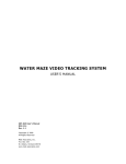
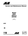
MODEL 28101
POSITION 1
POSITION 2
BREATHER AND
FILL PLUG
MAGNETIC DRAIN
PLUG
BREATHER.
FILL PLUG
MAGNETIC DRAIN
PLUG
POSITION 4
POSITION 3
BREATHER ANO
FILL PLUG
MAGNETIC DRAIN
PLUG
BREATHER AND
FILL PLUG
OIL LEVEL
MAGNETIC DRAIN
PLUG
The oil capacity for positions 1 and 2 is1½quarts or 1.42 liters (approximate).
This unit can be installed in any one of four different positions. The oil capacity is approximately 2½quarts or
2.37 liters for positions 3 and 4. The above drawings show the oil level for each installation and the position of
the drain plug, fill plug, and breather.
MODEL 28102
POSITION 1
BREATHER AND
FILL PLUG
POSITION 2
BREATHER AND
F I L L P LUG
MAGNETIC DRAIN
PLUG
MAGNETIC DRAI N
PLUG
This model is a double pump drive and can be installed in either one of two different positions. The a b o v e
drawings show the oil level and the location of the breather and magnetic plugs and filler plugs.
The approximate oil capacity in position 1 is 4½quarts or 4.23 liters and position 2 is 1½ quarts or 1.42
liters.
3
MODEL 28103
This unit, being an independent input can be mounted in any one of six different positions. The drawings
below show the location of the oil level, breather and magnetic drain plugs, in the various positions. The
approximate capacity in position 1 and 2 is 2½ quarts or 2.37 liters. In position 3 and 4 the oil capacity increases
to approximately 4 quarts or 3.97 liters. In positions 5 and 6, approximate oil capacity is 2½quarts or 2.37 liters.
BREATHER
AND FILL
PLUG
POSITION 1
BREATHER
AND FILL PLUG
POSITION 2
BREATHER
AND FILL
PLUG
MAGNETIC
DRAIN PLUG
POSITION 3
OIL LEVEL
POSITION 4
BREATHER AND
FILL PLUG
(APPROX. OIL CAP. 2½ OTS.)
POSITION 6
POSITION 5
4
MODEL 2 8104
POSITION 2
POSITION 1
BREATHER AND
FILL PLUG
MAGNETIC DRAIN PLUG
O i l LEVEL
POSITION 4
POSITION 3
OIL L E V E L
MAGNETIC DRAIN PLUG
BREATHER AND
FILL PLUG
MAGNETIC DRAIN
PLUG
The above drawings describe the four different positions in which this unit can be mounted and the location
of the oil level, breather, magnetic drain plugs, and fill plugs. The approximate oil capacity in position 1 is
4½ quarts or 4.23 liters, in position 2 and 3, 5½quarts or 5.21 liters, and in position 4, 1½ quarts or 1.42
liters.
MODEL 2 8111 , 1 2 , 13
POSITION 2
POSITION 1
MAGNETIC
DRAIN PLUG
BREATHER AND
F i l l PLUG
MAGNETIC DRAIN PLUG
OIL LEVEL
The three models of the triple pump drive series consists of the engine-mounted independent input and
clutch driven. The two mounting positions shown are applicable to all three models. The above drawings show the
oil level, magnetic plugs, breather, tapped mounting holes, and oil level plug location.
The oil capacity in position 1 is approximately 5½quarts or 5.21 liters and in position 2, a p p r o x i m a t e l y
quarts or 2.84 liters.
5
3
MODEL28105
0
0
0
0
This model is an engine mounted single pump direct drive. The assembly consists of an engine adapter,
pump adapter plate. and direct drive shaft. There is virtually no service on this model and no lubrication.
MODEL592M
BREATHER ANO
FILL PLUG
- O IL
O i l VOLUME:
7¾ Ots.
7.28 Liters
LEVEL
OIL VOLUME
3 1/8 Ot.
2.96 li1ers
6
MODEL 5 9 3 C
OIL VOLUME:
3½ 0t.
3.31 Liters
OIL VOLUME:
8 Qt..
7.57 Liters
MAGNETIC
DRAIN PLUG
MAGNETIC
DRAIN PLUG
NOTE: UNITS THAT HAVE "DIPSTICK" LEVEL GAUGES CONTAIN THE SAME VOLUME AND LEVEL OF
OIL AS THE EQUIVALENT UNIT WITH CHECK PLUG LEVELS.
FUNK PUMP DRIVE
MODEL 594M
OIL VOLUME: 7¾Qts.
7.33 Liters
MAGNETIC DRAIN PLUG
7
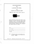
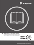
612P PUMPDRIVE
HORIZONTAL MOUNTING
FIGURE N 0 . 1
OIL LEVEL
OIL CAPACITY
¾ Qt. or .709 liters
VERTICAL MOUNTING
NOTE: Continuous operation above 68 HP (50.73
kW} (horiz. pos.) or 20 HP (14.92 kW} (vert.
pos.) should have provisions for auxilliary
cooling.
FIGURE NO. 2
NOTE: 612M & 612C Pump Drives have the same
volumetric oil capacity.
OIL CAPACITY
3/8 Qt. or .355 Liters
8
613P PUMP DRIVE
OIL LEVEL
OIL CAPACITY
1¼ Qts.
1.183 Liters
STANDARD MOUNTING
FIGURE NO. 3
NOTE: 613M and 613C Pump
Drives have the same
volumetric oil capacity.
OIL CAPACITY
:¾Qt.
.709 Liters
INVERTED MOUNTING
9
FIGURE NO. 4
OIL L E VE L S AND CAPACITIES SERIES
56000
BREATHER AND
FILL PLUG
MAGNETIC DRAIN PLUG
Oil Level Check Plugs
Capacity 9 Qts.
8.52 Liters
Capacity shown is typical for Models 56001
thru 56009.
Oil Level Check Plugs
Capacity 3 U.S. Gal.
11.36 Liters
Capacity shown istypical for Models 56010 thru
56015.
NOTE: DUE TO LUBRICATION SYSTEM DESIGN, MODELS 56000 SERIES, SHOULD ONLY BE
MOUNTED AND OPERATED IN HORIZONTAL POSITION SHOWN ABOVE. OPERATION IN ANY
OTHER POSITION MAY BE DETRIMENTAL TO GEARS AND BEARINGS.
10
CLUTCH ADJUSTMENT & LUBRICATION
SPEC. NUMBER
MODEL NUMBER
RATIO
SERIAL NUMBER
LUBRICATION
0
CLUTCH-Apply small amount of lubricant to clutch throout collar once a day.
POWER TAKE-OFFS - Apply small amount of lubricant to shaft bearings
every 50 hours. Gun fittings below.
REDUCTIONS - See service manual for type, grade, and quantity of
lubrication.
CLUTCH ADJUSTMENT - SL type clutch. This is a spring loaded type,
and need no adjustments.
0
FUNK MFG. CO.
CLUTCH INSPECTION PLATE FOR "SL" TYPE CLUTCHES
MODEL NUMBER
SPEC. NUMBER
SERIAL NUMBER
RATIO
LUBRICATION
O
CLUTCH - Apply small amount of lubricant to clutch throwout collar once a day.
POWER TAKE-OFFS - Apply small amount of lubricant to shaft bearings every 50 hours.
Gun fittings below.
REDUCTIONS - See service manual for type, grade, and quantity of lubrication.
CLUTCH ADJUSTMENT (OVERCENTER TYPE ONLY)
O
IMPORTANT - If clutch does not pull, heats, or operating lever jumps out, adjustment is
required. To adjust clutch, remove hand hole plate, turn clutch until adjusting lock
pin can be reached. Pull adjusting pin out and turn adjusting yoke to right or
clockwise until operating lever requires a distinct pressure to engage. A new
clutch requires several adjustments until friction discs are worn in.
FUNK MFG. CO.
CLUTCH INSPECTION PLATE FOR OVERCENTER TYPE CLUTCHES
11
CLUTCH DRIVEN MODELS
SAFE OPERATING SPEEDS
SPECIFICATIONS
CLUTCH
MODEL
NUMBER
C 108
C 110
C 111
SP 211
SP 114
SP 214
2400
Heavy Duty
Working
Torque
228
328
387
910
810
Newton
Metre
309
445
525
1234
1098
2400
1620
2197
MAXIMUM SAFE
OPERATING SPEEDS
OVER CENTER CLUTCHES
3100
3100
2850
2850
Heavy Duty
The clutch is used to start inertia loads with frequencies up to sixty (60) engagements per hour. Even more
important is that the clutch can start the heaviest inertia load within four (4) seconds and that the product of
seconds of clutch slip per engagement times the number of engagements per hour be under 180.
Heavy Duty applications may raise the clutch outer surface temperature to under 150° F (65. 6° C) rise above the
ambient air temperature.
The clutch must be selected according to its horsepower absorption capability.
Examples: PTO starting average inertia loads whose starting load is 180% of the running load. Also Rock
Crusher applications where the clutch is not used to "break loose" jammed loads.
12
Pump Mounting Position Codes
28000, 59000, and 61000 Pump Positions
1 Pump
Direct
Pos. 1
28102, 28104, 28180
592M, 592C. & 592P
Pos. 1
Pos. 4
Pos. 2
28101, 28103, 28275
Pos. 1
28211, 28212, & 28213
593M, 593C, & 593P
Pos. 2
594M, 594C, 594P
Gear box and pump mounting positions are shown to standardize communications between customer and
factory (vendor) should questions concerning engineering or service arise.
Gear box mounting positions are shown as Pos. 1 or Pos. 2, etc. Pump location positions are shown by letters
A, B, C, etc.
13
PUMP MOUNTING POSITIONS
All Views Are Top Views
Unit arrangement (check the desired configuration)
5. Special Requirements:
14
SERIES
56000
SERIES
28000
MODEL NUMBER CODE
PUMP DRIVE UNITS
1. Direct Drive Models
A. Single pump clutch driven - The model
numbers for these units will consist of8 digits
divided into four sections as follows:
28 TXX cx x (28TXXCXX)
A
B
C D
1. Section A is always 28and stands for the
28000 series.
2. Section B indicates a clutch operated direct
driven unit and designates the nominal clutch
size.
T10 = 1O " clutch
T11 = 11½" clutch
3.Section C designates the clutch housing size.
C1 = S.A. E. No. 1 Housing
C2 = S.A.E. No. 2 Housing
C3 = S.A.E. No. 3 Housing
C4 = S.A.E. No. 4 Housing
4.Section D designates the size of pump to be
driven.
A = S.A.E. "A" Pump
B = S.A.E. "B" .Pump
C = S.A.E .."C" Pump
D = S.A.E .."D". .Pump
EXAMPLE:
28 T11 C2 D (28600XX)
SAE "D" Pump
SAE No. 2 Clutch Housing
11 Y2'' Clutch
28000 Series
B.Single pump Engine Mounted (Plate Driven)
The model numbers for these units will consist
of 6 or 7 digits divided into 3 sections as follows:
28 105 XX (28105XX)
A
B
C
1. Section A is always 28 and stands for the
28000 series
2. Section Bis always 105 and indicates a single
pump direct driven unit.
3. Section C designates the size of the engine
flywheel housing and special features as follows:
A = SAE No. 1 Housing
B = SAE No. 2 Housing
C = SAE No. 3 Housing
D = SAE No. 4 Housing
E = SAE No. 5 Housing
F = SAE No. 5 Housing with starter cut-out
G = SAE No. 5 Housing on Ford 172 and
192 (for "B" pumps)
SE= Special SAE "E" Pump Mount with flywheel housing per spec.
15
EXAMPLES:
28 105 D (281050)
SAE No. 4 Housing
Single Pump Direct Drive
28000 Series
28 105 SE (28105SE)
Special "E" Pump Mount
j
Single Pump Direct Drive
28000 Series
2. Gear Driven Models
A. Independent Input Models - The model numbers for these units consist of 6 or 7 digits
divided into 3 sections as follows:
28 XXX XX (28XXXXX)
A
B
C
1.Section A will be 28 which stands for the
28000 series.
2.Section B is a 3 digit number that designates
the
number of pump mounting positions as
follows:
104 = 2 pumps
103 = 1 pump
212 = 3 pumps
3. Section C consists of 1 or 2 digits that designate the type of drive flange assembly as
follows:
A = Standard drilled flange assembly
B = 13/s-10 spline assembly
C = 2114inch keyed shaft assembly
D = Slotted flange assembly
E = No drive flange assembly
F = Standard drilled flange assembly with
through shaft
G = 3/e-10 spline assembly with through
shaft
H = 2½ inch keyed shaft assembly with
through shaft
J = Slotted flange assembly with through
shaft
AD = Input disconnect assembly
B. Engine Mount (Plate Driven) Models - The
model numbers for these units consist of six
digits divided into three sections as follows:
28 XXX X
A B C
1. Section A will be 28 which stands for the
28000 Series.
2. Section B is a three digit number that designates the number of driven pumps as follows:
101 = 1 pump
102 = 2 pumps
211 = 3 pumps
3. Section C consists of 1 letter that designates
the engine flywheel housing size as follows:
A = SAE No. 1 housing
B = SAE No. 2 housing
C = SAE No. 3 housing
D = SAE No. 4 housing
E = SAE No. 5 housing
F = SAE No. 5 housing with starter cut out
G = SAE No. 1 housing with through shaft
H = SAE No. 2 housing with through shaft
J = SAE No. 3 housing with through shaft
K = SAE No. 4 housing with through shaft
L = SAE No. 5 housing with through shaft
C. Clutch Driven Models - The model numbers for
these units consists of 6 digits divided into three
parts as follows:
28 xxx X
A-B-c
1. Section A will be 28 which stands for the
28000 series.
2. Section 8 is a three digit number that designates the number of driven pumps as follows:
275 = 1 pump
180 = 2 pumps
213 = 3pumps
3. Section C consists of 1 digit letter that designates the engine flywheel housing size and
special clutch features as required:
A = SAE No. 1 housing
B = SAE No. 2 housing
C = SAE No. 3 housing
D = SAE No. 4 housing
E = SAE No. 1 housing with T.D. SP-211
clutch
F = SAE No. 1 housing with T.D. SP-114
clutch
G = SAE No. 2 housing with T.D. SP-211
clutch
H = SAE No.3 housing with T.D. SP-211
clutch
J = SAE No. 1 housing with through shaft
K = SAE No. 2 housing with through shaft
L = SAE No. 3 housing with through shaft
M = SAE No. 4 housing with through shaft
N = SAE No. 1 housing with through shaft
and SP-114 clutch
P = SAE No. 1 housing with through shaft
and SP-211 clutch
R = SAE No. 2 housing with through shaft
and SP-211 clutch
S = SL-111 clutch with 1 •116inch offset
T = SL-111 clutch with 2Ye inch offset
U = SAE No. 1 housing with T.D. SP-214
clutch
V = SPECIAL bearing release collar
EXAMPLE:
28 275 C (28275C)
LSAE No. 3 housing
1 pump drive
I
28000 series
28 213 M (28213M)
L SAE No. 4 housing with
through shaft
3 pump drive
28000 series
I
IL _
16
SERIES
59000
MODEL NUMBER CODE
PUMP DRIVE
CLUTCH DRIVEN AND PLATE DRIVE MODELS
59 XP XX
(59XPXXXXX)
A B
C DEFG
1. Section A - 59 = 59000 Series
2. Section B - 2P = 2 Pump Drive
3P = 3 Pump Drive
4P = 4 Pump Drive
3. Section C - Flywheel Size or Clutch Size
08 = 8"
10 = 1O" Single
Plate
11 = 11112'' Single
10 = 10"
Plate
14 = 14" Single
11 = 10112''
Plate
14 = 14"
21 = 11w· 2 Plate
24 = 14" 2 Plate
4. Section D - C = Clutch Driven P = Plate Driven
5. Section E - Clutch or Flywheel Housing Size
1 = SAE No. 1
2 = SAE No. 2
3 = SAE No. 3
6. Section F - Ratio Code = •
7. Section G - (Optional) E = Thru shaft Extension.
F = Thru Pinion Shaft on Clutch
EXAMPLES: Driven Models: F = SAE "A" Center
Pad on Plate Driven Models
5
9 r
1 1 0 C 2 A \ 5 � P, 1 g : ; ;: 1
SAE No. 2 Housing
Clutch Driven
1O" Flywheel
2 Pump Model
'-------59000
Series
59 3P NS P 1 H (593 PNSP1H)
3
'----- ---
17
;;
f ousing
Plate Driven
Non Standard Flywheel
3 Pump Model
59000 Series
INDEPENDENT INPUT MODELS
59 XP E
(59XPFX)
A B CD E
1. Section A - 59 = 59000 Series
2. Section B - 2P = 2 Pump Drive; 3P = 3 Pump
Drive; 4P = 4 Pump Drive
3. Section C - F = Flange Drive
4. Section D - Ratio Code = *
5. Section E - (Optional) E = Thru shaft extension
EXAMPLES:
59 2P F A (592PFA)
1.00:1 Ratio
Flange Drive
2 Pump Model
59000 Series
59 4P F B (594PFB)
.836:1 Ra!io
I
I
Flange Dnve
4 Pump Model
59000 Series
•See next page for ratios
MODEL NUMBER CODE
PUMP DRIVE
*
4 Pump Ratio Code
A = .778:1 Speed Up (1.286)
B = .836:1 Speed Up ( 1.196)
E = 1.1960:1 Reduction
F = 1.286:1 Reduction
G = 1.00:1
H = 1.383:1 Reduction
J = .723:1 Speed Up (1.383:1)
K = 1.113:1 Reduction
L = .898:1 Speed Up (1. 113)
*
2 Pump Ratio Code
A = 1.00:1
B = 1. 10: 1 Reduction
C = .909:1 Speed Up (1.10)
D = 1 .40:1 Reduction
E = .714:1 Speed Up (1.40)
F = 1.545:1 Reduction
G = .647:1 Speed Up (1.545)
H = .585:1 Speed Up (1.709)
*
3 Pump Ratio Code
A = .778:1 Speed Up (1.286)
B = .836:1 Speed Up ( 1.196)
C = .846:1 Speed Up (1.182)
D = 1. 182: 1 Reduction
E = 1. 196: 1 Reduction
F = 1.286:1 Reduction
G = 1.00:1
H = 1.283:1 Reduction
J = .723: 1 Speed Up ( 1.383)
K = .898:1 Speed Up (1.113)
L = 1.113:1 Reduction
18
SERIES
59000
SERIES
61000
FUNK MANUFACTURING
COMPANY MODEL CODE
PLATE DRIVEN AND CLUTCH DRIVEN MODELS
61 S X X XX X X X X (61SXXXXXXXX)
A BCD
E FGHJ
1. Section A - 61 = 61000 Series
2. Section B - S = Engine mounted (adapter to SAE
flywheel housing)
3. Section C - S.A. E. Flywheel housing size
3 = SAE No. 3
45 =
= SAE
SAE No.
No. 45
4. Section D - P = Plate Drive; C = Clutch Drive
5. Section E - Flywheel size (nominal clutch size)
71/2 = 71/2"
08 = 8"
N0S == 10"
Non Standard
1
6. Section F - 2 = 2 Pump Drive;
3 = 3 Pump Drive
7. Section G - L.H. Pump Size
A = SAE "A"; B = SAE "B";
C = SAE "C"
8. Section H - R.H. Pump Size on two Pump Models
Upper center pump Size on three
pump models
A = SAE "A"; 8 = SAE "8";
C = SAE "C"
9. Section J - R.H. Pump Size on three pump
models only
A = SAE "A"; B = SAE "8'';
C = SAE "C"
19
EXAMPLES:
61 S 3 C 08 2 B B (61S3COB288)
I
I
-----SAE
.. _ _ _ _ _
�------61000
61 S 4 P
::;
r 1 f I t iJ =
.. _ _ _ _
- -----SAE
�-----'---------61000
-
Pump Drive
8" Clutch
Clutch Drive
No. 3 Housing
Engine Mount
Series
L 2
)
center
SAE B Pump L.H.
3 pump drive
1 O" flywheel
Plate Drive
No. 4 Housing
Engine Mount
Series
INDEPENDENT INPUT MODELS
61M X X X X X {61MXXXXX)
ABCDEFG
1. Section A - 61 = 61000 Series
2.Section B - M = Independent Input
3. Section C - K = Keyed input shaft;
N = Splined Input Shaft;
NS = Non Standard;
D = Input Disconnect Assembly
4. Section D - 2 = 2 Pump Drive;
3 = 3 Pump Drive
5. Section E - Left Hand Pump Size
A = SAE "A";
B = SAE "B";
C = SAE "C"
6.Section F - Right Hand Pump Size on 2 pump
Models
Upper Center Pump Size on 3 pump
Models
A = SAE "A";
B = SAE "B";
C = SAE "C"
7.Section G - Right Hand Pump Size on 3 pump
Models
A = SAE "A";
B = SAE "B";
C = SAE "C"
EXAMPLES:
61 M N 2 A B (61MN2AB)
SAE "B" Pump Right Side
SAE "A" Pump Left Side
2 Pump Drive
Spline Input Shaft
Independent Input
..__ _ _ _ _
61000 Series
61 M K 3 C B C (61MK3CBC)
SAE "C" Pump Lower Right
SAE "B" Pump Upper Center
I j L SAE "C" Pump Lower Left
3 P4mp Drive
Keyed Input Shaft
' - - - - - - - I n d e p e n d e n t Input
'--------61000
Series
DIRECT ENGINE MOUNT MODELS
fil. XX � � � � {61 XXXXXX)
AB
CDEF
1. Section A - 61 = 61000 Series
2. Section B - WA= Adapter to Wisconsin Engine
Series VG40 with CA-69-C-2
Crankshaft; 1948 Bearing Retainer and PH-278 Rear Crankshaft Seal
WB = Adapts to Wisconsin Engine
Series V4610 and V465D with
CA-75-C-1 Crankshaft and PL150-1 Key
WC= Adapts to Wisconsin Engine
VH4D with CA-71-A-14 Crankshaft; BG-210-C-13 Rear Bearing Retainer and PH-200-8
Rear Crankshaft Seal.
ON = Adapts to Onan Engine Series
NH and MS with crankshafts
equivalent to Onan Drawing
Number 110C960
VW = Adapts to Volkswagen Engine 3.
Section C - Indicates length input shaft and flange
type as follow:
A = 27" Shaft, 7C, BC, and 1800
Flange
B = 4.94" Shaft, 7C, BC, and 1800
Flange
C = 4.31" Shaft, 6C, 7C, and 1600
Flange
0 = 2112'' Diameter with V2 keyway
4.Section D - Indicates how many pump drive pads 5.
Section E - Indicates left hand pump pad size on 2
pump model and lower left hand pump
pad size on 3 pump model
6. Section F - Indicates right hand pump pad size on
2 pump model and upper center pump
pad size on 3 pump model
7. Section G - Indicates lower right hand side pump
pad size on 3 pump model
20
SERIES
56000
MODEL NUMBER CODE
PUMP DRIVE
1. CLUTCH DRIVEN MODELS
A. The Model Number is divided into three sections
560 XX X
ABC
1. Section" A" is always 560 and designated the
56000 Series
2. Section "8" indicates clutch driven models as
follows:
"01" = 2 Pump Clutch Driven
"04" = 3 Pump Clutch Driven
"11" = 5 Pump Clutch Driven
3. Section "C'" indicates clutch size and clutch
housing size, as follows:
"A" = SP-114 or SP-214 Clutch and SAE
No. O Clutch Housing.
"C" = SP-211 Clutch and SAE No. 1 Clutch
Housing
"D" = SP-114 or SP-214 Clutch and SAE
No. 1 Clutch Housing
"F" = SP-211 Clutch and SAE No. 2 Clutch
Housing
"G" = SL-214 Clutch and SAE No. 1 Clutch
Housing
2. PLATE DRIVE MODELS
A. Three Section Model No. as Above:
560 xx X
ABC
1. Section "A" (560) Indicates basic 56000
Model
2. Section "8" Indicates Plate Driven Models as
follows:
"02" = 2 Pump Plate Driven
"05" = 3 Pump Plate Driven
"12" = 5 Pump Plate Driven
21
3. Section "C" Indicates Engine Bell H o u s i n ! t
and Engine Adapter Size
A = SAE No. 0
8 = SAE No. 1
C = SAE No. 2
3. INDEPENDENT INPUT MODELS
A. Three Section Model Number
560 xx X
ABC
1. Section "A" Indicates Basic 56000 Model
2. Section "B" Indicates Independent Input
Models as follows:
"03" = 2 Pump Models (10" Gear Centers)
"06'' = 3 Pump Models (10" Gear Centers)
"13" = 5 Pump Models (16" Gear Centers)
"15" = 5 Pump Models with Drive Flange
Offset to Side
3. Section "C" Indicates type input flange as
follows:
A = Flange to fit spicer 1700 and 1800 or
mechanics 7C and 8C.
8 = 3 Inch Diameter shaft with 3/4'' Keyway
4. LINE SHAFT INPUT MODELS
A. Three Section Model Number
560 XX X
ABC
1. Section "A" Indicates Basic Model 56000. W ,
2. Section "B" Indicates Line Shaft Input Models
as follows:
"07" = 3 Pump Models
"08" = 4 Pump Models
"09" = 5 Pump Models
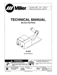
TYPICAL DISASSEMBLY AND
ASSEMBLY PROCEDURES FOR MODELS
18000, 59000, & 61000 PUMP DRIVES
2
1
3
4
5
LI
-
-
-
-
-
-
-
J
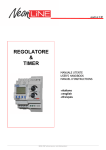
Power Train with engine mounted Pump Drive
1. Engine
2. Flywheel Cover
3. Engine Adapter
4. Pump Drive
5. Hydraulic Pumps
DISASSEMBLY
1. Drain oil from pump drive gear box by removing allen head pipe plug from bottom of main case.
2. Remove hydraulic pumps by removing capscrews, or nuts from studs. Remove pumps straight away from
pump drive.
3. Remove pump drive from engine by removing capscrews, holding engine adapter housing to flywheel cover
of engine. Remove pump drive straight away from engine.
a. Clutch driven models:
Remove nut and starwasher holding clutch bearing lubrication line to engine adapter. The clutch and drive
shaft assembly may tend to remain with engine. Should this occur, move clutch throwout handle in a
manner which will allow clutch sliding sleeve trunions to disengage from throwout fork.
b. Flex plate driven models:
The drive shaft will remain with either the drive plate or the pump drive box. Be prepared to retrieve drive
shaft from either.
22
Fig. 4
Pump drive gear box should bepositioned sothat the
hydraulic pump adapter pads are facing up.
Remove place bolts or nuts from studs and lift
adapter pads up from gear box.
Fig. 5
Lift driven gears and their bearings from pump drive
box. This can be done by hand since the bearings are
slip fitted to the housing and pump adapter bores.
Bearings are press fitted to gear hubs. It may be
necessary to tip gear slightly to clear pinion gear
bearing pocket.
Fig. 6
After all driven gears and their bearings have been
removed, position gear box sothat the engine
adapter (clutch housing or independent input flange)
is facing up.Remove place bolts and lift engine
adapter upfrom gear box. Lift pinion gear and bearings from pump drive box.
23
r .-,i·...;:;:. ,..
·---··- J -.'_""_.;.....,-...
• "*-' :::!.'«....
Fig. 7
Should replacement of oil seal be required, drive oil
seal toward engine side of engine adapter.
Note: Drive in direction of arrow.
·.,
.•
..;...;...---,
Fig. 8
...., .,. _.
Toremove bearings from gear hubs. use gear puller
or Arbor Press.
REASSEMBLY
For assembly of models 28000. 59000, and 61000 pump drives, use reverse procedure of figures 1 through 8.
NOTE: Plastic cord used for gasket material under pump adapter plates and input housing is not reusable.
Replace with new material when reassembling. See drawing number 4028802 for installation of cord
gasket. Place bolts should not be re-used. Clean the old loctite out of the bolt hole threads. Install new
place bolts with loctite 262 on models 28000 and 59000, the engine adapter, clutch housing and pump
pad. Place bolts are torqued to 200ft. lbs. (271 nm). If studs are used in pump drive pad, torque studs to
150 ft. lbs. (203 nm). The 61000 pump drive engine adapter, clutch housing and pump drive pads are
torqued to 150 ft. lbs. (203 nm).
24
REASSEMBLY
Replacement of oil seal
Install oil seal from engine side of engine adapter.
The rubber lip of the oil seal must point toward the
inside of pump drive gear box.
Note: Drive in direction of arrow.
Clutch driven models
Install clutch and shaft assembly into pinion gear of
pump drive before mounting to engine.
SERVICE PARTS
WHEN ORDERING SERVICE PARTS THE FOLLOWING INFORMATION LOCATED ON THE
IDENTIFICATION TAG, MUST BE GIVEN TO
PARTS DEPARTMENT PERSONNEL.
MODEL NUMBER
SPEC NUMBER
SERIAL NUMBER
RATIO
Drive plate models
When installing drive plate on flywheel, be sure the
long end of the drive plate hub is toward the engine.
The hub should slide into the pilot bearing bore of the
flywheel to insure proper alignment of the drive hub
and drive shaft.
Note: Arrow indicates engine side
4028802
TYP. ADPT. PLT.
ENDS BEYOND FLANGE
Remove protective paper strip
from cord and with adhesive side
next to metal, install around pilot.
cross ends as shown behind bolt
hole and let ends extend beyond
flange.
Use
caution
in
assembly to case to prevent
gasket dislocation.
B
©
25
D
Do not attempt to re-use this gasket. For
reassembly use new gasket material. On
flywheel housings involving more than 4
bolt holes - be sure string gasket lap joint
falls behind one hole location.
Using bolt or stud fastener, not behind an
unused hole.
Typical Disassembly And Assembly
Procedures For
NOTE: The 56000 Model pump drive gear box uses
a split case with the two halves dowelled and
bolted together, do not disconnect these two
halves until the entire pump drive assembly
has been removed from the machine.
1. Drain oil from pump drive gear box
2. Remove hydraulic pumps from pump drive
by removing the capscrews and pulling the
pumps straight away from the gear box.
3. Remove the pump drive from the engine, it
engine adapter is mounted. If not mounted
to engine, disconnect and remove the
pump drive from the input source.
Remove dowell pins by driving them toward the engine (or input) side of pump drive.
(Arrow indicates dowel! pin and direction of removal.)
If air breather (A) is damaged, replacement is necessary. Do not plug the elbow. (8) indicates engine
adapter.
..
"-- -· · ··-•·'---·
;
",.
Place pump drive on work bench with engine (or
input) side up. Remove engine adapter or independent input drive flange from gear box.
.
'"
; - .;;;=:r,•..• ,....7i.. . ,-· .....
.-
...( ' 'i
·
r
\
'
:,...r·;
:-
.'
.
..
"\ ·
T
•: .-.1,._,l''
!i
'T
-·*""· .-...;,.
·r+.er'ff"'"'J11l:"l..........-1.,
• .'.
, .., .
<
r
"
h•
.
'
l
f
t
.;.,- ·:r'J!,4
.J ..7
""7?'- r
••
r·
...:.....;;i,,[tt."l,·
;,-:.-' ... ""-:-"'
J ••-
.:
...."T17
�:�A._..-:�·;�.-�,.;.;:.,..,. ....... .,..,.;.,, _ _ _ _ _ . .�':�t�t.:t•:,;Yf1'!'J··rrt��·;::, :·::·:f� ·��;0"'�: \.�--.,.,.,:-:�...;,. -.� /
Remove the 24 capscrews, lockwashers and nuts
which couple together the two halve (input and output
housing) of pump drive. Lift the upper (input) half
; straight up and remove gasket. (A) Input housing (8)
· Output housing. Arrow indicates direction of removal.
A
•
ASSEMBLY
For assembly of the Model 56000 Pump Drive, use
reverse procedure of Figures 1 through 9. The 4
place bolts for the engine adapter or clutch housing
should not be re-used. Clean the place bolt hole
threads to remove the old loctite. Install the new
place bolts with loctite 262 and torque to 200 ft. lbs.
(271 nm). Torque the 24 capscrews and nuts to 75 f t
lbs.
;;....._.
Fig. 7
Remove the two capscrews which hold the oil trough
to lower (output housing) and remove trough.
If trough cannot betipped and pulled out from under
the gears, it will be necessary to lift each gear and
bearing assembly from the output housing until
trough can be removed.
Arrows indicate oil trough capscrews.
8. With oil trough removed, lift gears and their bearings from output housing. This can be done by
hand since bearings are slip fitted to the housing
bores and press fitted to gear hubs.
9. To remove bearings from gear hubs use a gear
puller or arbor press.
SERVICE PARTS
When ordering service parts, the following information located on the identification tag must be given to
parts department personnel.
Model Number
Spec Number
Serial Number
26
MODEL
56000