1
US007273315B2
(12)
United States Patent
(10) Patent N0.:
US 7,273,315 B2
(45) Date of Patent:
Sep. 25, 2007
Huang et al.
(54)
MIXING DEVICE WITH VARIABLE SPEED
DRIVE AND RELATED CONTROL
2,616,673 A
3,422,330 A
FEATURES
(75) Inventors: Joseph C. Huang, Dayton, OH (US);
’
’
u er _
4,822,172 A *
4/1989
Stottmann ................. .. 366/142
4,860,816 A *
8/1989
Bond .................... .. 164/155.3
4,893,942 A *
1/1990 Stottmann ................. .. 366/279
5,000,578 A
3/1991 Artin etal.
Subject to any disclaimer, the term of this
patent is extended or adjusted under 35
Filed:
(Continued)
FOREIGN PATENT DOCUMENTS
May 10, 2004
(65)
CH
691103 A5 * 4/2°°1
Prior Publication Data
US 2004/0208082 A1
Oct. 21, 2004
(Continued)
Related US. Application Data
51
t' t l.
10/1987 MoIiln e a
OH (Us)
(21) Appl. N0.: 10/842,369
(63)
Ernsteretal. ......... .. 241/1011
4/1989 Obradovlc
U.S.C. 154(b) by 197 days.
(22)
2/1986 C
4’8l9’460 A
Assignee: Premark Feg LLC, Wilmington, DE
Notice:
4/1976
Howard A. Hartley, Jr., Brookville,
(US)
(*)
3,951,351 A *
4568193 A
4’697’929 A
Brian E. Bader, Spring?eld, OH (US);
(73)
11/1952 Van Guilder
1/1969 Swanke
OTHER PUBLICATIONS
continuation'in'pan of application NO~ 10/329,040’
?led On Dec- 23, 2002-
Service manual entitled “Models H-600 and H-600-T and L-800
MiXers,” by Hobart Corporation (Sep. 1977).
I n t . C] .
C ontmue
'
d
B01F 7/30
2006.01
B0117 15/00
E2006 01;
'
Primary Examiner4Charles E. Cooley
(52)
U 5 Cl
366/206_ 366/601
(58)
Field of Classi?cation Search .......... .. 366/96i98,
(74) Attorney, Agent, or FirmiThompson Hine LLP
(57)
ABSTRACT
366/l99i207, 288, 601; 99/348
See application ?le for complete search history.
(56)
References Cited
A mixing machine includes a drive assembly and control
U.S. PATENT DOCUMENTS
ing controlled acceleration and deceleration. A boWl receiv
ing portion may be movable between a lowered position and
a raised position With a poWer boWl lift mechanism provided
system for making speed changes on the ?y and for provid
1,767,002 A
6/1930 Meeker et al.
1,781,321 A *
11/1930
Dehuif ...... ..
474/31
2,019,911 A *
11/1935 Meeker et a1.
366/288
2,181,079 A *
11/1939
2,185,155 A
2,251,903 A
12/1939 Meeker et al.
8/1941 Anstice et a1.
Dehuif ..................... .. 366/207
to effect such movement. Advanced control features and
special function modes may also be provided.
7 Claims, 9 Drawing Sheets
US 7,273,315 B2
Page 2
U.S. PATENT DOCUMENTS
7,014,354 B2*
3/2006 Donthnier et al. ........ .. 366/203
2002/0093877 A1
7/2002 Brunswick etal.
5,087,864 A *
5,140,248 A *
2/1992
Abel ------------------------- -- 318/34
Rowan er a1- - 318/811
2003/0165068 Al*
2004/0008005 Al*
9/2003
Tomonaga ................. .. 363/37
8/1992
1/2004
5,204,606 A *
4/1993
Kuwahara et al. ........ .. 318/800
2004/0l20213 Al>l<
6/2004
Sakai etal. ............... .. 318/801
Short et a1‘ “
366/l97
5,306,083 A
5348393 A
4/1994 Caldwell er a1~
9/1994 PaPPaS, Jr
5,472,276 A
12/1995 R?termann er a1~
5547278 A
5,570,955 A
5,653,535 A *
2004/0120215 Al*
2004/0208082 Al*
8/1996 Xie
6/2004 Huang et al. ............. .. 366/203
10/2004 Huang et al. ............. .. 366/206
2005/0122836 A1
6/2005 Boyle et a1.
2005/0141340 Al*
6/2005
Donthnieretal. ........ .. 366/207
11/1996 SWartWout et al.
8/1997 Xie et al. ................. .. 366/100
FOREIGN PATENT DOCUMENTS
5,690,427 A *
11/1997
5,736,828
5,844,343
5,872,435
5,906,432
4/1998 Turner et a1.
12/1998 Horst
DE
DE
3613231 A
10/1987
3912361 A1 * 10/1990
2/1999 Bolte etal.
EP
0293915
5/1999 Wade et al.
EP
8/1999 Xie .......................... .. 366/100
EP
A
A
A
A
5,934,802 A *
Jennings ................... .. 366/100
1130761
5,955,861 A
9/1999 Jeong etal.
EP
1433382
5,957,021 A
6,066,074 A
9/1999 Meredith etal.
5/2000 Marcinkiewicz
FR
GB
2805177
2134674 A
6,313,597 B1
11/2001 Elliott etal.
JP
12/1988
710442 A2 *
11114394
5/1996
9/2001
6/2004
*
8/2001
8/1984
4/1999
6,429,612 Bl*
8/2002
Kurne et a1. .............. .. 318/139
6,704,212 B2*
3/2004
Furukawa et al. .......... .. 363/41
D490,271 S
5/2004 $11011 et 61
Instruction manual entitled “H600 & L800 Mixers,” by Hobart
6,756,757
6,750,629 B2 *
6/2004 MarcinkieWiCZ
ShigemiZu 6t et .......
a1~ .. 318/801
The
Corporation
Characteristics,
(Dec, Design and Applications of Switched Reluc
6,883,959
6,953,278 B2 *
10/2005
4/2005
Donthnier
Short et al.et........
al. ..
6,972,541 B2 *
12/2005
Matsushiro et al. .
7,005,825 B2 *
2/2006
366/203
tance Motors and Drives, Dr. J.M. Stephenson and Dr. R]. Blake,
366/206
318/801
68 pageS.
* cited by examiner
U.S. Patent
Se .25 2007
Sheet 1 0f 9
US 7,273,315 B2
U.S. Patent
Sep. 25, 2007
US 7,273,315 B2
l IXIFIHI III
l6
,. n a r
18
II I
Sheet 2 0f 9
l-kv
U.S. Patent
Sep. 25, 2007
Sheet 3 0f 9
US 7,273,315 B2
U.S. Patent
Sep. 25, 2007
Sheet 4 0f 9
US 7,273,315 B2
2Hz:
:5
Saw“
L.F2"
m
‘a
\Q
mum:as:
25
1052 :33.“553258
"65u
V
5::n5is
E5
8.6S2583
i8225:
m.5522%:,
M
I
n526;:
l Tl
8%m5:
wA:5::82“.
U.S. Patent
Sep. 25, 2007
fr
i
C)
GD
Sheet 5 0f 9
US 7,273,315 B2
U.S. Patent
Sep. 25, 2007
Sheet 6 0f 9
US 7,273,315 B2
U.S. Patent
Sep. 25, 2007
Sheet 7 0f 9
Fig.
7
US 7,273,315 B2
U.S. Patent
Sep. 25, 2007
Sheet 8 0f 9
US 7,273,315 B2
a
v
m
n,
J
_.
0
-.r_
w
m
c
L
"1 O
n
m
U
A
m
A
v
n
.n
.T
_.
q
u
#
m
x
u
|r¥unIH-|1.a:
u
m
_.
_
s
////////7///
U.S. Patent
Sep. 25, 2007
Sheet 9 0f 9
US 7,273,315 B2
JZIO
CONTROL
vmwnnwnunnnn
“in 1 u u WWW[ WL
US 7,273,315 B2
1
2
MIXING DEVICE WITH VARIABLE SPEED
DRIVE AND RELATED CONTROL
FEATURES
tool. A mixer body supports the head and includes a boWl
receiving portion, the boWl receiving portion mounted for
movement betWeen a loWered position aWay from the head
and a raised position toWard the head. A poWer boWl lift
CROSS-REFERENCE TO RELATED
APPLICATION
mechanism is provided for moving the boWl receiving
portion betWeen the loWered position and the raised posi
This application is a continuation-in-part of application
Ser. No. 10/329,040 ?led Dec. 23, 2002, the entire speci?
cation of Which is incorporated herein by reference.
portion is in the raised position. A drive assembly is pro
vided for effecting rotation of the rotatable output member.
A ?rst user input mechanism is provided for initiating
TECHNICAL FIELD
mixing and a second user input mechanism is provided for
activating the poWer boWl lift mechanism. A control system
receives input from each of the ?rst user input mechanism,
The present application relates generally to commercial
mixers utilized for mixing food products such as dough, and
the second user input mechanism and the sensor, and con
trols both the poWer boWl lift mechanism and the drive
more particularly to a commercial mixer With a variable
assembly. The control system includes a plurality of speed
settings for the drive assembly. In response to the ?rst input
mechanism being actuated to initiate a mixing operation at
a ?rst speed setting When the boWl receiving portion is
beloW the raised position, the control system operates to
tion. At least one sensor detects When the boWl receiving
speed drive and desirable control features.
BACKGROUND
20
It is knoWn in existing commercial mixers to provide
activate the drive assembly at a sloW speed Which is less than
multiple speed settings for the mixers. The various available
mixing speeds are primarily driven by a motor through
the ?rst speed setting.
combinations of gears and/ or belts and/or variable adjustable
pulleys, Where mechanical adjustments are made to change
mix speeds. Many such devices require that the mixer be
stopped in order to change speeds.
25
US. Pat. No. 5,934,802 is representative of a mixer that
did not utiliZe mechanical adjustment of any drive linkage or
gear system to change speeds, but instead simply adjusted
memory storing a plurality of operating settings and has at
30
the output speed of a DC motor. HoWever, control of the DC
35
drive assembly connected for effecting rotation of the rotat
able output member. A user interface includes at least a
40
SUMMARY
In one aspect, a mixing machine includes a head extend
ing over a boWl receiving location, the head including a
rotatable output member for receiving a mixer tool. A drive
assembly includes a drive motor and a drive linkage opera
tively connected to effect rotation of the rotatable output
member. A user interface includes at least one input mecha
nism and a control system receives input from the user
45
speed selection mechanism for selecting one of multiple
speed levels. A control system receives input from the speed
selection mechanism and effects operation of the drive
assembly, the control system including memory storing a
?rst plurality of speed settings corresponding to a ?rst mixer
con?guration and a second plurality of speed settings cor
responding to a second mixer con?guration. Only one of the
?rst plurality of speed settings or the second plurality of
speed settings is active at any given time.
BRIEF DESCRIPTION OF THE DRAWINGS
50
interface and is connected for controlling operation of the
drive motor to provide closed loop control of motor speed
and acceleration to effect mix speed changes on the ?y solely
FIG. 1 is a perspective vieW of a mixing machine With top
cover removed;
FIG. 2 is a side elevation of the mixing machine of FIG.
by adjusting motor speed.
In another aspect, a mixing machine includes a head
termined sequence of inputs from the at least one user input
mechanism.
In another aspect, a mixing machine includes a rotatable
output member positioned over a boWl receiving area and a
to provide sufficient torque.
Accordingly, it Would be advantageous to provide a mixer
that can change speeds on the ?y and provide sufficient
torque for commercial mixing applications.
least one special function mode enabling at least one of the
operating settings to be changed. The control system is
placed in the special function mode by receiving a prede
motor Was implemented in a relatively simple manner, using
a potentiometric speed control sWitch to adjust a PWM
signal delivered to the motor. No feedback of motor speed
Was provided. In larger commercial mixers, use of a DC
motor is impractical due to the siZe of the DC motor needed
In yet another aspect, a mixing machine includes a
rotatable output member positioned over a boWl receiving
area and a drive assembly connected for effecting rotation of
the rotatable output member. At least one user input mecha
nism is provided and a control system receives inputs from
the user input mechanism. The control system includes
55
extending over a boWl receiving location, the head including
1 in partial cross-section;
FIG. 3 is a perspective vieW of an upper portion of the
a rotatable output member for receiving a mixer tool and a
mixing machine of FIG. 1;
gear system thereWithin for effecting rotation of the rotatable
FIG. 4 is a control system schematic for the mixing
machine of FIG. 1;
FIG. 5 illustrates the user interface of the mixing machine
of FIG. 1;
output member. A sWitched reluctance motor has an output
operatively connected to drive the gear system. A sWitched
reluctance drive operates the sWitched reluctance motor. A
60
user interface includes at least one input mechanism and a
FIGS. 6 and 7 illustrate one embodiment of a pivotal boWl
control unit receives input from the user interface and is
mounting system; and
connected for controlling operation of the sWitched reluc
tance drive.
In a further aspect, a mixing machine includes a head
including a rotatable output member for receiving a mixer
65
FIG. 8 shoWs one embodiment of a boWl guard assembly.
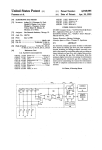
FIG. 9 is a control system schematic of a mixer system
With a variable frequency drive.
US 7,273,315 B2
3
4
FIGS. 10 and 11 depict exemplary PWM voltage signals
of varying duty cycles delivered to respective motor termi
speeds, such as those often used in mixing applications for
planetary mixers. In another embodiment, an AC induction
motor might be used.
Referring to FIG. 4, an exemplary control arrangement for
nals.
FIG. 12 depicts the exemplary effective voltage seen by
the motor terminals based upon the PWM voltage signals of
a sWitched reluctance motor embodiment is shoWn and
includes a control system 70 formed by a control unit 72 and
a sWitched reluctance (“SR”) drive 74. The control unit 72
FIGS. 10 and 11.
DETAILED DESCRIPTION
location 18. The boWl receiving location 18 may be de?ned
includes a processor or microcontroller based timer control
unit 76 and an analog control circuit 78. A user interface 80
enables a user to input desired operations to the control unit
72, and a plurality of sensors S1, S2, and S3 are also
connected With the control unit 72 and indicate the status of
various parts of the mixer as Will be described in more detail
beloW. In an embodiment using an AC induction motor, a
by a boWl receiving portion 20 of the mixer body 13, Where
variable frequency AC drive could be used in place of the SR
the boWl receiving portion 20 has a spaced apart curved arms
21 de?ning a curved shape to match the boWl 22. The head
includes a doWnWardly extending rotatable output member
drive 74.
Referring again to FIGS. 1 and 5, an exemplary user
interface 80 is located on the head 16 and includes a plurality
Referring to FIGS. 1-3, a mixing machine 10 is shoWn and
includes a base 12, a mixer body 13 including a column 14
extending upWard from the base 10, and a head 16 extending
outWard from the column 14 and over a boWl receiving
24 that can receive a mixer tool such as dough hook, Whisk
or other tool. The head 16 and upper portion of the column
14 typically include a detachable cover (not shoWn) for
20
enclosing the components.
The mixing machine includes a drive assembly 26 for
effecting rotation of the rotatable output member 24. In the
illustrated machine the drive assembly is formed in part by
a gear system 28 Within the head 16 and having an upWardly
extending input drive shaft 30. In the case of a planetary
mixer, the gear system 28 may take the form of a planetary
gear system, in Which case the rotatable output member 24
rotates about its oWn axis 32, With the axis 32 orbiting
around a central boWl axis 34 during mixing operations.
Also forming part of the drive assembly is a drive motor 36
that is mounted and located in line With the column 14 and
includes an upWardly extending output shaft 38. A drive
linkage 40 connects the motor output shaft 38 to the gear
system input shaft 30 and may be formed by the illustrated
belt 42 and pulleys 44 and 46. Alternative drive linkages
could take the form of chain and sprocket combinations,
additional gearing and/or or bar-type linkages. The illus
trated drive linkage 40 is a ?xed linkage, meaning that the
drive ratio betWeen the motor output shaft 38 and the gear
system input shaft 30 does not change.
The boWl receiving portion 20 may be mounted for
movement betWeen a raised position toWard the head 16 and
a loWered position aWay from the head 16, the raised
speed, a mix start button 92 and a mix stop button 94. It is
25
forWard poWer path in the analog control circuit 78 When
depressed in one direction (e. g., upWard for BOWL UP) and
30
BOWL DOWN), With both poWer paths of the analog
control circuit 78 delivering poWer to the poWer lift mecha
nism 54 for initiating either up or doWn movement as may
35
puts pulses directly to the timer control 76 via the signal path
labeled TIME. The timer control 76 responsively drives the
LED display 86 to re?ect the selected/changing mix time
40
76 via the signal path labeled SPEED. The timer control 76
responsively drives the LED display 90 to re?ect the
45
50
on a pair of spaced apart guide rails 52 on the front side of
actuator, may be provided for effecting upWard and doWn
55
selected speed (e.g., Stir, l, 2, 3, 4). Of course, in the case
of each input mechanism it is contemplated that other types
of devices could be used. It is also contemplated that more
or less input mechanisms could be provided.
The mix start button 92 may be a normally-open push
button sWitch connected in the analog control circuit 78 and
the mix stop button 94 may be a normally-closed pushbutton
sWitch connected in the analog control circuit 78. 51 While
numerous types of sensors could be used, in a simple form
the sensors S1, S2, and S3 may be limit sWitches incorpo
rated in the analog control circuit 78 that open or close one
or more signal or poWer paths based upon monitored mixer
parts. For example, relative to FIG. 4, sensor sWitch S1 may
be located to close only When the boWl receiving portion 20
60
to mounts 58 unitary With an internal casting of the head, and
a loWer moving rod portion 60 may be connected to mounts
desirable because it can provide high torque at loW operating
(e.g., in minutes and seconds). The speed input mechanism
88 may be a rotating knob connected to a six-position sWitch
such as a Carling sWitch providing inputs to the timer control
the column 14. A poWer lift mechanism 54, such as a linear
62 on the support 50 as shoWn in FIG. 3.
In one embodiment, a sWitched reluctance motor is pro
vided as the drive motor 36. A sWitched reluctance motor is
be desired. The time input mechanism 84 may be a rotating
knob connected to a bi-directional rotary encoder that out
support 50 and the support 50 rides upWard and doWnWard
lift mechanisms could be used, or a manual mechanism
controlled by a crank handle could be used. Where a linear
actuator is used as shoWn, a top portion 56 may be secured
closes a reverse poWer path in the analog control circuit 78
When depressed in the other direction (e.g., doWnWard for
ered position being used for boWl installation and removal as
Ward movement of the boWl receiving portion 20. In one
embodiment, a suitable linear actuator is the Warner Electric
DC24-10A5 series DC motor 8" stroke length gear train and
ACME screW actuator. Alternatively, other types of poWer
recogniZed that display types other than LED could also be
used. Referring to FIGS. 1 and 4, the boWl up/doWn sWitch
82 may be a double-pole double-throW sWitch that closes a
position being used during mixing operations and the loW
Well as for installation and removal of mixing tools on the
rotatable output member 24. In this regard, the curved arms
21 of the boWl receiving portion 20 connect With a central
of input mechanisms including a boWl up/doWn sWitch 82
for activating the poWer boWl lift mechanism 54, a time
input mechanism 84 and associated LED display 86 for
inputting a desired mix time, a speed input mechanism 88
and associated LED display 90 for inputting a desired mix
moves to its raised position (e.g., BOWL IS UP), sensor
sWitch S2 could be located to close only When a mixer boWl
is placed in an operating position relative to the boWl
receiving portion 20 (e.g., BOWL IS LOCKED) and sensor
sWitch S3 may be located to close only When a boWl guard
positioned betWeen the boWl 22 and the head 16 is in its
65
closed position (e.g, GUARD IS CLOSED). In this regard,
the user interface 80 could be provided With one LED or
other controllable visual indicator for indicating When the
US 7,273,315 B2
5
6
bowl is in the raised position, another LED or other con
attempt is made to immediately drive the motor at the
trollable visual indicator for indicating When the boWl is in
the operating position and/or another LED or other control
lable visual indicator for indicating When the boWl guard is
closed.
desired ?nal speed. The acceleration is controlled by the SR
drive 74 based upon feedback from the encoder 106. Simi
larly, if the motor is operating at one speed and the speed
setting is changed via the user interface 80, the timer control
76 communicates the neW speed setting to the SR drive 74
and the SR 74 drive then operates to controllably accelerate
With respect to the boWl up sensor sWitch S1, a limit
sWitch can be located toWard the front portion of column 14
to be contacted by an upper portion of the control support 50
When the boWl receiving portion 20 is moved to the raised
or decelerate the motor 36 to the neW speed setting. In one
embodiment the acceleration may be controlled according to
a pre-established acceleration time set in memory of the SR
drive 74. In another embodiment the timer control 76 may
position.
With respect to the boWl locked sensor sWitch S2, in one
embodiment the boWl 22 may be pivotally mounted at one
side to the boWl receiving portion 20 to move betWeen a
path 100. As used herein the term “acceleration time” refers
non-operating position (FIG. 6) and an operating position
to the amount of time taken to accelerate from one speed to
(FIG. 7). The pivotal mount may be achieved by a combi
nation of pins on the boWl receiving portion 20 and bracket
occur at a drive motor speed setting of 2500 rpm, if an
openings on the boWl 22 that engage each other to form a
acceleration time of ?ve seconds is communicated to the SR
hinge. The boWl 22 is held in the operating position by a
locking bracket 93 that couples With a retractable pin 95 that
is spring-biased in an upWard position. When the boWl 22 is
in the closed, operating position a portion of the boWl 22
actuates a sWitch plate assembly toWard the front portion of
motor 36 from Zero rpm to 2500 rpm in the speci?ed 5
seconds. In another embodiment the timer control 76 may
communicate an “acceleration rpm value” to the SR drive
communicate an acceleration time to the SR drive 74 via
another. In other Words, at the start of a mixing operation to
drive 74, the SR drive responds by accelerating the drive
20
74, With the SR drive then operating to accelerate the motor
the column 14 to close the sensor sWitch S2 behind the
sWitch plate. Further details of such pivoting boWl arrange
ments are provided in US. patent application Publication
by the acceleration rpm value over a preset time. As an
25
example, Where an acceleration rpm value of 100 is deliv
ered to the SR drive 74, the SR drive 74 operates to change
No. US. 2002/0,093,877 Al, published Jul. 18, 2002. Other
the speed of the drive motor by 100 rpm every second, Where
sensor con?gurations could be used, inclusive of mixers
Where the boWl 20 is not pivotally mounted to the boWl
receiving portion, in Which case the sWitch could simply
one second is an exemplary preset time in the SR drive.
Memory of the timer control 76 could store a table of
acceleration times or acceleration rpm values according to
detect Whether or not the boWl 20 has been loaded onto the
30
the speed changes being made. Of course, other types
boWl receiving portion 20.
acceleration control values could be stored in such a table of
With respect to the boWl guard closed sensor sWitch S3,
reference is made to FIG. 8 shoWing an exemplary suitable
memory of the timer control 76 to be communicated by the
timer control 76 to the SR drive 74 during speed changes.
The combined operation of the control unit 72 and SR drive
74 advantageously enables closed loop control of mixer
speed changes on the ?y, Without having to adjust a gear box
boWl guard as described in US. Pat. No. 5,306,083. A front
portion 97 of the boWl guard rotates betWeen an open
position for access to the boWl and a closed position for
35
mixing operations. A reed-type sWitch 99 in combination
With a magnet 101 that moves With portion 97 of the boWl
guard detects When the boWl guard is in the closed position.
Other sensor con?gurations could be used, including a limit
sWitch actuated by physical contact With a portion of the
40
nicate a desired current limit to the SR drive 74, Where a
boWl guard.
current limit may also be stored in memory of timer control
Referring again to FIG. 4, the control unit 72 controls
operation of the SR drive 74. In particular, the timer control
76 communicates With the SR drive 74 via communications
76 for each speed. Alternatively, the current limit may be
45
bus 100 and also outputs a RUN or STOP directive to the SR
drive 74 via path 102. The SR drive 74 can also receive an
emergency stop (E-STOP) directive on path 104. The SR
drive 74 controls three-phase poWer delivery to the SR
motor 36 and receives a speed indicating feedback signal
pre-set in memory of the SR drive 74. The SR drive 74 uses
the current limit to monitor operation of the motor and can
operate to prevent the current delivered to the motor 36 from
exceeding the set current limit.
The control system 70 can be used to implement both
count doWn mix operations and count up mix operations. A
50
count doWn mix operation is one that occurs for a time
period that is set by the operator, preferably With the time
display 86 displaying a continuously decreasing time
remaining for the mix operation. A count up mix operation
from a rotary encoder 106 of the motor 36 as Well as a
temperature feedback signal from a temperature sensor 108.
The SR drive 74 also monitors and can control the level of
current delivered to the motor 36. Thus, the SR drive 74
provides closed-loop speed and acceleration control of the
or drive linkage ratio.
In addition to communicating desired speed and an accel
eration control value to the SR drive 74 When a mix
operation is started, the timer control 76 may also commu
is one that continues until the operator causes the mix
55
operation to stop (e.g., presses the mix stop button 94) or
motor 36, and can prevent motor overload and reduce inrush
until some situation, other than time, causes the mix opera
current during motor starting operations.
tion to stop (e.g, the boWl is moved out of its operating
position or the boWl guard is opened). During the count up
mix operation the time display 86 preferably displays a
In this regard, in one embodiment the timer control 76
includes memory storing a pre-set motor speed correspond
ing to multiple positions of the sWitch 88. When the timer
control 76 directs the SR drive 74 to begin running the motor
36, the timer control 76 communicates the desired speed to
the SR drive 74 via path 100. The SR drive 74 then operates
60
In one embodiment, the timer control 76 includes memory
storing a preset mix time for multiple positions of the speed
selection sWitch 88. In other Words, When an operator
desires to start a mix operation the operator may ?rst utiliZe
to controllably accelerate the motor 36 from Zero rpm to the
desired speed, With the controlled acceleration reducing
undesired inrush current. Inrush current is a surge of current
that can occur When a motor is started, particularly Where an
continuously increasing time of the mix operation.
65
speed input mechanism 88 to select the desired speed. When
the timer control 76 recogniZes the selected speed setting
(e.g., position of sWitch) it responds by accessing from
US 7,273,315 B2
7
8
memory a corresponding preset time for that speed setting
and drives the display 86 to display the preset time. If that
preset time is the time desired by the operator, the operator
the motor from the loW speed to the set speed. Further, When
the boWl receiving portion 20 reaches the raised position the
timer control 76 responsively maintains a run signal to the
SR drive 74 on line RUN/STOP Without requiring the mix
does not need to set the time. However, if the preset time is
start button to be continuously depressed. According to the
not the time desired by the operator, the operator then
utilizes the time input mechanism 84 to change the time
(e. g., upWard or doWnWard). In this case the timer control 76
responsively drives the display 86 to re?ect the change. The
timer control 76 may also responsively update memory to
change the preset mix time for the selected speed setting to
the neW time input by the operator. In one embodiment the
memory update occurs immediately When the operator
changes the time, While in another embodiment the memory
update only occurs once the mix start button is depressed.
Further, Where an operator changes mix time during a
described control characteristic, When an operator sets a
desired speed and mix time While the boWl is in a loWered
position and then simultaneously and continuously presses
mix start and boWl raise, the boWl raises and the mixing tool
is rotated at a sloW speed. The sloW rotation of the mixing
tool reduces resistance of the food product Within the boWl
22 to the insertion of the mixing tool as the boWl is raised.
In one embodiment the sloW speed may be a sloWest speed
setting (e.g., STIR) of the mixer or, in another embodiment,
may be a speed betWeen the tWo sloWest speed settings.
When the boWl 22 and boWl receiving portion 20 reach the
mixing operation (e.g., during a count doWn mix operation),
the timer control 76 could responsively update memory to
change the preset mix time for the selected speed setting to
raised position as indicated be sensor sWitch S1, the mix
that input by the operator.
Without requiring further action from the operator. Thus,
When the boWl receiving portion 20 is beloW the raised
position the control system 70 only permits operation of the
As another example of the use of preset mix times for
each speed setting, Where the mixer is running at a set speed
operation proceeds automatically at the higher set speed
20
for a certain time (e.g., during a count doWn type mix
motor 36 at a sloW speed, but When the boWl receiving
operation), if the operator changes the selected speed setting
by using speed input mechanism 88, the timer control
portion 20 is in the raised position the control system 70
permits operation of the motor 36 at any of the available
responsively drives the display 90 to re?ect the neWly
selected speed setting, communicates the neW speed setting
to SR drive 74 to change the motor speed accordingly and
25
Relative to the boWl guard, the preferred control charac
teristics based upon boWl guard position are to disable/
prevent operation of the drive assembly motor 36 Whenever
the boWl guard is not in the closed position (e.g., by opening
also accesses from memory the preset time corresponding to
the neWly selected speed setting and drives the display 86 to
re?ect the accessed preset mix time. The timer control 76
speed settings.
30
a poWer delivery path to the motor 36), but to permit the
then treats the accessed preset mix time as the neW mix time
boWl receiving portion 20 to be raised or loWered even When
for the count doWn mix operation. In such an embodiment,
the boWl guard is not in the closed position.
changing the speed setting during a count doWn mixing
operation automatically changes the duration of the count
indicates the boWl is not in the closed position, the control
doWn mix.
In one embodiment, When the boWl locked sensor S2
35
The control system 70 may also be con?gured to imple
ment additional control characteristics as desired. For
example, When the sensor S1 indicates that the boWl receiv
ing portion 20 is beloW the raised position and the mix start
button 92 is depressed to initiate a mixing operation at a set
speed, the control system 70 can responsively operate to
only permit operation of the motor 36 at a loW speed less
than the set speed. If the boWl up/doWn sWitch 82 is also
depressed to move the boWl receiving portion 20 upWard,
the control system can responsively operate to actuate the
40
to be loWered. HoWever, in another embodiment the control
system 70 could be con?gured to permit the boWl receiving
45
poWer boWl lift mechanism 54 appropriately at the same
time that the motor 36 operates at the loW speed. This control
characteristic is implemented by the timer control 76 out
putting a signal on the BOWL LIFT line, or by otherWise
affecting the analog control circuit 78 (e.g., by closing a
circuit path in the analog control circuit), to alloW forward
50
poWer (boWl up direction) to be delivered to the poWer boWl
lift mechanism 54; outputting a signal on the TIMER
READY line, or otherWise affecting the analog control
circuit (e.g., by closing a circuit path in the analog control
55
circuit), to energiZe a relay that closes contacts to alloW
poWer delivery to the motor 36; outputting a run signal to the
SR drive 74 on the RUN/ STOP line; and communicating the
loW speed, instead of the set speed, to the SR drive 74 via
bus 100. Preferably, this control characteristic is only
e?‘ected When the boWl guard is in the closed position.
detect When the boWl receiving portion is located toWard the
loWest position (e.g., the sensor sWitch Would identify When
the boWl receiving portion is in the loWer 1/3 of the total
movement length betWeen the loWered and raised positions).
The control system 70 could then be con?gured so that (1)
When the boWl receiving portion is in the loWer region as
indicated by the additional sensor sWitch, the boWl receiving
portion is able to move either upWard or doWnWard, regard
less of Whether the boWl is in the closed position, and (2)
When the boWl receiving portion is higher than the loWer
region, the boWl receiving portion is able to move upWard
only if the boWl is in the closed position and the boWl
receiving portion is able to move doWnWard regardless of
Whether the boWl receiving portion is in the closed position.
In both of the latter embodiments, When the boWl is not in
the closed position the control system 70 Would disable/
prevent operation of the drive assembly motor 36.
The described mixing machine may also be provided With
65
to only certain personnel, such as service personnel. As used
herein the terminology “special function mode” refers to any
Further, this control characteristic is preferably only imple
set speed to the SR drive 74 and the SR drive 74 accelerates
portion and boWl to be both raised and loWered even if the
boWl is not in the closed position. In still another embodi
ment, an additional sensor sWitch could be provided to
60
mented if the mix start button 92 is continuously depressed
and the boWl up/doWn sWitch 92 is continuously depressed.
When the boWl receiving portion 20 reaches the raised
position the timer control 76 responsively communicates the
system 70 prevents the boWl receiving portion and boWl
from being raised (e.g., by opening a circuit path in the
analog control circuit to prevent delivery of forWard poWer
(boWl up direction) to the poWer boWl lift mechanism 54)
and also disables/prevents operation of the drive assembly
motor 36, but permits the boWl receiving portion and boWl
one or more special function modes that may be accessible
non-mixing mode for the mixing machine. Examples of
US 7,273,315 B2
10
special function modes include retrieving data log informa
tion (e.g. mix hours, total operating hours or fault records)
settings for multiple mixer model con?gurations. In the
simplest example ?rst and second mixer con?gurations are
maintained in memory of the timer control 76, changing or
provided and the memory stores a ?rst group or plurality of
setting stored mix speeds corresponding to the positions of
speed settings corresponding to the ?rst mixer model con
the mix speed sWitch 88, changing or setting stored current
limits for the various mix speeds or changing the active
model con?guration of the mixing machine.
?guration and also stores a second group or plurality of
In one embodiment access to each of the special functions
requires no more than use of the time input mechanism 84
and/ or speed input mechanism 88 of the user interface 80. In
and therefore available for use, at any one time. When the
special function mode for mixer model setting is entered, the
timer control 76 drives the time display 86 to display the
particular, the timer control 76 can be con?gured to look for
certain combinations of inputs from one or both mechanisms
identity of the active model. To change model settings the
speed input mechanism 88 is repeatedly turned betWeen tWo
in order to activate or enter one or more special function
positions to advance to a next model setting, Which is in turn
modes. Essentially, one or both of the speed input mecha
nism 88 and the time input mechanism 84 can be used to
displayed in the time display 86. To leave the special
function mode the speed input mechanism 88 is turned to the
stir position, and Whichever model setting is displayed at
that time is made active, meaning the speed settings for that
mixer model con?guration are made active for subsequent
speed settings corresponding to the second mixer model
con?guration. Only one group of speed settings is active,
enter a preset combination or access code (e.g., predeter
mined sequence of inputs) into the timer control 76, Which
responds by entering the special function mode. Where
multiple special function modes are used, multiple combi
mixing operations.
nations or access codes can be provided, one for each mode. 20
By Way of example, an exemplary combination for a special
function mode may start With a certain speed sWitch position
(e.g., position 6ithe position aligned With display 90),
folloWed by a certain entered time (e.g., 1:24), folloWed by
a different speed sWitch position (e.g., position 4), folloWed
by another set time (e.g., 1:52), folloWed by the initial speed
sWitch position (e.g., position 6). The timer control 76 then
drives the displays 86 and 90 to display information perti
nent to the particular special function mode, and the time
input mechanism 84 and speed input mechanism 88 can then
be used to retrieve or change information for that particular
mode. Where the interface is more advanced, such as in the
case of a keypad, the key pad could be used to input the
combination.
By Way of example, Where the mode enables retrieval of
25
In another embodiment, a hidden sWitch might be pro
vided behind an overlay of the user interface 80 for initiating
special function modes. Depression of the sWitch may
activate special function modes in a read only format unless
a jumper is in place at a particular location in control unit 72,
in Which case the special function modes could be enabled
in a read/Write format.
In one embodiment, the timer control 76 stores two
different types of speed settings. Referring to FIGS. 1 and 2,
30
the mixer head 16 includes a poWer take oif 200 at the front
thereof With an internal drive component 202 that is also
35
driven by the gear system Within the head. Such poWer take
offs 200 have been commonly used for years in connection
With auxiliary food processing mechanisms, such as veg
etable slicers, cheese graters and meat grinders, that are
driven by component 202. In the noted embodiment of timer
fault records, upon entering the special function mode the
control 76, one or more speed settings are stored for use in
timer control 76 drives display 86 to display a fault count for
a pre-established initial fault condition code. To retrieve
information on a next pre-established fault code the speed
input mechanism 88 can be turned betWeen certain speed
put component 24 and one or more speed settings are stored
for use in connection With devices When attached to poWer
take olf 200. This con?guration enables an operator to
connection With mixing operations using the rotatable out
40
positions, With the timer control 76 responding by driving
implement both (i) speed settings that have been selected as
optimum or desirable for operations using the poWer take oif
display 86 to display other fault condition information To
leave the special function mode the speed input mechanism
(e.g., slicing, grating and grinding) and (ii) speed settings
88 could be turned to a certain position (e.g., the STIR speed
that have been selected as optimum or desirable for normal,
position).
As another example, Where the mode enables resetting of
mix speeds, upon entering the special function mode the
timer control 76 drives display 86 to display the active mixer
model. The operator then turns the speed input mechanism
88 to the speed position for Which a change is desired. The
timer control 76 responsively drives display 90 to display
the selected speed position and drives the time display 86 to
display the rpm speed as retrieved from memory for that
speed sWitch position. The operator then rotates the time
input mechanism 84 to change the rpm speed. The procedure
is repeated for any speed position desired to be changed. To
leave the special function mode the speed input mechanism
88 is set to the stir speed position, at Which time the neWly
45
50
55
these settings to the operator. For example, the speci?c
embodiment shoWn in FIG. 5 could be altered by replacing
the “3” and “4” speed setting designations of the speed
sWitch With designations that read “GRIND” for meat grind
ing and “SLICE” for vegetable slicing. In such an embodi
ment speed sWitch settings “STIR”, “1” and “2” Would be
used by the operator for in-boWl mixing operations, the
speed sWitch setting “GRIND” Would be used by the opera
tor When a grinding unit is attached to the poWer take olf 200
and the speed sWitch setting “SLICE” Would be used by the
entered speeds are recorded in memory of the timer control
76. In this regard, the rpm speed corresponding to the stir
in-boWl mixing operations. In connection With mixer
embodiments con?gured in this manner, the user interface
80 of FIG. 5 can be con?gured to e?fectively communicate
60
operator When a slicing unit is attached to the poWer take oif
200.
In another embodiment, the control unit 72 may operate
speed position of mechanism 88 is preferably pre-set and
With the user interface 80 to display error codes to the
cannot be changed. A similar technique Would be used set
current limits for each speed if a current limit special
operator. For example, if the boWl sWitch S2 indicates the
boWl is not closed and the operator temporarily depresses
function mode Were activated.
Another advantageous special function mode enables a
mixer model setting to be selected. In this regard, memory
of the timer control 76 may store multiple groups of speed
65
the mix button 92 in attempt to mix, the control unit 72 can
e?fect display of a close boWl indicator in either of displays
86 and 90 to communicate to the operator the need to pivot
the boWl to the closed position in order for normal mixing
US 7,273,315 B2
11
12
to be started. Where the displays 86 and 90 are of the LED
type, the closed boWl indicator may be a simple indicator
210 can be con?gured to provide controlled acceleration and
deceleration When mix speed changes are made.
In one implementation of a mixer incorporating the con
such as “bc”. Where the displays 86 and 90 are more
trol system of FIGS. 9-12, Where the mixer is a 20 Qt. mixer,
the mixer includes a stir speed and speeds 1, 2 and 3, Which
speeds may be stored in memory and selected by the
interface 80 as previously described. At the highest speed,
speed 3, the motor speed may be less than 3500 RPM, and
produce a torque of at least 25 in-lb, and the planetary speed
may be at least 130 RPM. The planetary speed de?nes the
speed at Which the output shaft of the mixer orbits about the
center axis of a boWl during mixing. In one example, at the
stir speed, the planetary speed may be betWeen 18 and 28
RPM, the motor speed may be betWeen 320 and 500 RPM,
and the motor torque is at least 40 in-lb; at speed 1, the
planetary speed may be betWeen 36 and 56 RPM, the motor
speed may be betWeen 640 and 1000 RPM, and the motor
advanced, the indicator could likeWise be more advanced. In
another example, if the boWl up sensor S1 indicates the boWl
is not in the upWard position and the operator temporarily
depresses the mix button 92 in attempt to mix, the control
unit 72 can effect display of a boWl up indicator (e.g., such
as “bu”) in either of displays 86 and 90 to communicate to
the operator the need to raise the boWl to the upWard position
in order for normal mixing to be started. If both problems
exist When the operator temporarily depresses the mix
button 92, the control unit can display the boWl up indicator
in one of the displays 86 and 90 and the close boWl indicator
in the other display or, in the alternative, the control unit 72
can cause a single one of the displays to alternatingly display
both indicators. The displays 86 and 90 could also be used
to display other error codes if desired.
Referring noW to FIGS. 9-12, a more detailed description
of the embodiment including an AC induction motor and
torque is at least 80 in-lb; at speed 2, the planetary speed
20
least 40 in-lb; and at speed 3 the planetary speed is betWeen
variable frequency drive is provided. In particular, user
interface 80 is associated With a control system 200 includ
ing the variable frequency drive With a recti?cation section
202 for converting AC input 204 to DC, Which is ?ltered by
?lter section 206 to remove ripple. The AC input 204 is
illustrated as 3-phase but could also be single phase. The
?ltered DC voltage is input to a sWitching section 208,
illustrated as including 3 transistor half bridge circuits. A
control section 210 is connected to control the transistors
25
less than 1500 RPM, and produce a torque of at least 165
in-lb, and the planetary speed may be at least 60 RPM. In
one example, at speed 1, the planetary speed may be
30
betWeen 20 and 30 RPM, the motor speed may be betWeen
500 and 750 RPM, and the motor torque is at least 175 in-lb;
at speed 2, the planetary speed may be betWeen 26 and 36
RPM, the motor speed may be betWeen 650 and 900 RPM,
and the motor torque is at least 135 in-lb; and at speed 3 the
35
speed the frequency of the output remains substantially
planetary speed is betWeen 35 and 50 RPM, the motor speed
is betWeen 875 and 1250 RPM, and the motor torque is at
least 170 in-lb. A sloWer stir speed may also be provided.
In another implementation of a mixer incorporating the
control system of FIGS. 9-12, Where the mixer is a 140 quart
constant. Each output takes the form of a PWM voltage
signal of varying duty cycle as shoWn by VAN in FIG. 10 ,
VBN in FIG. 11 and VCN (Waveform not shoWn) for the
outputs to the A, B and C terminals 212 of AC induction
motor 214. VAN and VBN depict output signals at a set
frequency, Which Would correspond to a certain motor
125 and 165 RPM, the motor speed is betWeen 2225 and
2950 RPM, and the motor torque is at least 28 in-lb.
In another implementation of a mixer incorporating the
control system of FIGS. 9-12, Where the mixer is a 60 quart
mixer, at the highest speed, speed 3, the motor speed may be
using PWM signals to produce a 3 phase variable frequency
output that is applied to the coil terminals 212 of motor 214.
The term 3 phase variable frequency output means that the
frequency of the output can be varied if desired to adjust
speed, hoWever, during operation of the motor 214 at a set
may be betWeen 70 and 100 RPM, the motor speed may be
betWeen 1250 and 1775 RPM, and the motor torque is at
40
mixer, at the highest speed, speed 3, the motor speed may be
less than 2500 RPM, and produce a torque of at least 320
in-lb, and the planetary speed may be at least 80 RPM. In
speed. The three Waveforms VAN, VBN and VCN are identical
one example, at speed 1, the planetary speed may be
in frequency and shape, but are phase shifted from each
other by one third of a cycle (120°). The effective voltage
by 1200 from each other, thus synthesizing balanced 3 phase
betWeen 21 and 31 RPM, the motor speed may be betWeen
525 and 775 RPM, and the motor torque is at least 690 in-lb;
at speed 2, the planetary speed may be betWeen 40 and 52
RPM, the motor speed may be betWeen 1000 and 1300
RPM, and the motor torque is at least 450 in-lb; and at speed
3 the planetary speed is betWeen 80 and 95 RPM, the motor
speed is betWeen 2000 and 2375 RPM, and the motor torque
is at least 300 in-lb. A sloWer stir speed may also be
Waveforms at the motor terminals 212. The fundamental
provided.
frequency of the effective voltage is varied by the control
section 210 by causing the frequency of output signals VAN,
9-12 are possible.
45
seen by the A-B motor terminals is shoWn in FIG. 12 as
VAN-VBN, having a fundamental frequency as represented
by the sinusoidal dashed line Waveform in FIG. 12. The
effective voltage seen by the B-C motor terminals and the
C-A motor terminals is similar to FIG. 12, but phase shifted
VBN and VCN to vary in the same Way. Because Winding
inductance ?lters out the high frequency components of the
PWM voltage signals, current in the motor Windings Will
50
Other implementations using the control system of FIGS.
55
It is to be clearly understood that the above description is
intended by Way of illustration and example only and is not
intended to be taken by Way of limitation. Other changes and
modi?cations could be made, including both narroWing and
broadening variations and modi?cations of the appended
60
claims.
What is claimed is:
have a frequency that is essentially the same as the funda
mental frequency of the voltage as shoWn in FIG. 12, but
Will be phase-shifted by approximately 90° due to the
inductance of the motor Windings. The characteristics of the
AC induction motor 214 Will generally cause the magnitude
1. A mixing machine, comprising:
a head extending over a boWl receiving location, the head
including a rotatable output shaft for receiving a mixer
of the motor Winding current to increase as the load on the
AC induction motor 214 increases and the motor 214 begins
to slip, thereby providing increased torque When needed.
The speed of motor 214 varies according to the fundamental
frequency of the synthesiZed Waveforms, and the control
65
tool, the head including a gear system thereWithin for
effecting rotation of the rotatable output shaft about its
axis and orbiting of the shaft axis about another axis;
US 7,273,315 B2
14
13
an AC induction motor having an output operatively
connected to drive the gear system;
a drive for operating the AC induction motor, the drive
6. The mixing machine of claim 1 Wherein the AC
induction motor has at least six poles.
including a recti?cation section for converting input
a head extending over a boWl receiving location, the head
including a rotatable output shaft for receiving a mixer
7. A mixing machine, comprising:
AC poWer to DC poWer and a sWitching section for
producing a 3 phase variable frequency output that is
tool, the head including a gear system thereWithin for
effecting rotation of the rotatable output shaft about its
axis and orbiting of the shaft axis about another axis;
an AC induction motor having an output operatively
connected to drive the gear system;
a drive for operating the AC induction motor, the drive
including a recti?cation section for converting input
applied to the AC induction motor, Wherein the sWitch
ing section is controlled to adjust frequency of the 3
phase variable frequency output to make mix speed
changes on the ?y solely by adjusting speed of the AC
induction motor;
a user interface including at least one speed input mecha
nism having a limited number of speed positions;
the drive is part of a control system including memory
AC poWer to DC poWer and a sWitching section for
producing a 3 phase variable frequency output that is
storing a plurality of distinct mix speeds corresponding
to the speed positions of the speed input mechanism;
Wherein at one mix speed of the plurality of distinct mix
speeds the motor speed is betWeen about 2225 and
2950 RPM and the planetary speed is betWeen about
125 and 165 RPM, and at a sloWer mix speed of the
applied to the AC induction motor, Wherein the sWitch
ing section is controlled to adjust frequency of the 3
phase variable frequency output to make mix speed
changes on the ?y solely by adjusting speed of the AC
20
plurality of distinct mix speeds the motor speed is
betWeen about 320 and 500 RPM and the planetary
speed is betWeen about 18 and 28 RPM.
2. The mixing machine of claim 1 Wherein the drive
operates to control acceleration When changing from one
mix speed to another.
3. The mixing machine of claim 1 Wherein the sWitching
section is controlled by a plurality of PWM control signals.
4. The mixing machine of claim 1 Wherein a maximum
speed of an output shaft of the AC induction motor for a
highest of the plurality of mix speeds is less than 3500 RPM.
5. The mixing machine of claim 1 Wherein the 3 phase
variable frequency output comprises ?rst, second and third
PWM voltage signals.
induction motor;
a user interface including at least one speed input mecha
nism having a limited number of speed positions;
the drive is part of a control system including memory
25
30
storing a plurality of distinct mix speeds corresponding
to the speed positions of the speed input mechanism;
Wherein at one mix speed of the plurality of distinct mix
speeds the motor speed is betWeen about 875 and 1250
RPM and the planetary speed is betWeen about 35 and
50 RPM, and at a sloWer mix speed of the plurality of
distinct mix speeds the motor speed is betWeen about
500 and 750 RPM and the planetary speed is betWeen
about 20 and 30 RPM.