1
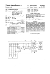
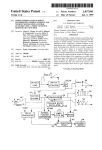
United States Patent [191
[11]
4,158,871
Leaming
[45]
* Jun. 19, 1979
[54] KIT FOR SERVICING TAPE CARTRIDGE
PLAYBACK UNIT
[76] Inventor:
Raymond C. Leaming, 721 S.
Washington, Liberal, Kans. 67901
[ “ ] Notice:
The portion of the term of this patent
subsequent to Dec. 27, 1994, has been
disclaimed.
Primary Examiner-Jay P. Lucas
Attorney, Agent, or Firm-Berman, Aisenberg & Platt
[57]
ABSTRACT
A kit for servicing the interior working parts of a car
tridge type tape playback unit comprising a completely
hollow cartridge case having parallel track guide means
disposed in its two sides. The hollow cartridge case is
[21] Appl. No.: 862,919
designed to actuate the unit when it is inserted in the
unit and provide the user of the kit with an unobstructed
[22] Filed:
view of the playback head, the capstan and the sensing
poles as well as other similarly disposed interior work
Dec. 21, 1977
Related US. Application Data
[63]
ing parts over which the tape would normally travel. A .
Continuation-impart of Ser. No. 609,009, Aug; 29, '
1975, Pat. NO. 4,065,801.
[51]
[52]
Int. c1.2 ....................... .. G11B 5/41; A47L 25/00
US. Cl. ...................................... .. 360/137; 15/32;
[58]
Field of Search ............... .. 360/137, 132, 128, 93;
[56]
15/246, 257, 100, 145, 159 R, 23
References Cited
360/ 132
U.S. PATENT DOCUMENTS
B 449,892
3/ 1976
3,407,431
10/ 1968
Thompson ......................... .. 360/ 132
3,761,994
10/ 1973
3,881,195
4/1975
Ono
3,955,214
5/1976
Post et al.
Melnik ...... ..
....... .. 15/32
Becht . . . . . .
. . . ..
360/128
. 360/128
360/137
OTHER PUBLICATIONS
tool holder having a plurality of interchangeable ser
vice heads is provided. Two of the heads, one of abra
sive material and the other of felt or the like, are formed
with a concave cleaning surface and are dimensioned so
as to be received between the guides in the side walls of
the cartridge case. Another cleaning head includes cut
ter blades and a magnet and is also sized so as to be
received within the guides. The guides are aligned with
the capstan so as to direct these heads into intimate
contact with the capstan surface. Another service head
is formed as a swab of cotton-like material and is de
signed for cleaning the sensing poles and playback head.
A still further service head is formed as a transparent
plate having indicia positioned thereon for checking the
alignment of the playback head, while yet another ser
vice head is formed as a metal probe for shunting the
sensing probes to check proper operation thereof.
Admiral Tape Player, #846, Chassis Service Manual,
(5-74), p. 5.
39 Claims, 21 Drawing Figures
U.S. Patent
26
Jun. 19, 1979
Sheet 1 of 4
4,158,871
KPLA v eA‘cK
“J2
'
US. Patent
Jun. 19,1979
Sheet 2 of4
‘4,158,871
kE
4
E=
I
n
d
-
4176.4,
F/G.8,
/32
US. Patent
Jun. 19, 1979
F/G,17
_
Sheet4 of4
10;‘L
62
’\\ \\ \\
6/
4,158,871
1
4,158,871
2
This typeof device has proven to be unsatisfactory in
KIT FOR SERVICING TAPE CARTRIDGE
PLAYBACK UNIT
many respects among which are the undue wear which
it causes on the playback head, the limited area of the
drive capstan which it is able to clean, the wear on the
CROSS-REFERENCE TO RELATED
drive capstan, and the build-up of foreign material
APPLICATION
which it causes on either side of the cleaning tape.
This application is a continuation-in-part of US. Ap
Other cleaning devices of various sorts have also been
plication Ser. No. 609,009, ?led Aug. 29, 1975 now US.
proposed, but none of these has been entirely successful.
Pat. No. 4,065,801, issued Dec. 27, 1977.
I am aware of the following patents, which are not
10 necessarily prior art with respect to my invention, in
BACKGROUND OF THE ‘INVENTION
this general area: US. Pat. Nos. 3,407,431, Melnick,
1. Field of The Invention
‘The present invention relates to servicing various
1968; 3,439,922, Howard, 1969; 3,594,850, Wellington,
1971; 3,647,990, Eu], 1972; 3,701,178, Kuntz, 1972;
3,761,994, Becht, 1973; 3,881,195, Ono, 1975; 3,955,214,
Post, 1976; 3,997,919, Thompson, 1976.
components of a magnetic tape player of the cartridge
type and more particularly relates to a kit for effecting
cleaning, testing and alignment of the player compo
nents.
2. Description of The Prior Art
SUMMARY OF THE INVENTION
.
In accordance with the present invention, there is
Recently, the use of cartridge-type prerecorde
provided a kit for servicing the interior working parts of
tapes, and particularly those of the 8-track variety, has 20 a cartridge-type tape playback unit which includes a
become extremely widespread. Along with the conve
hollow cartridge designed to be inserted in the normal
nience and pleasure which these cartridges provide,
tape cartridge receiving slot of the playback unit and to
have come problems which are peculiar to the construc
tion of the playback units.
The playback units of the cartridge-type include
playback heads and related structures which are nor
mally mounted in an enclosed location, since the car
actuate the machine. Also included in the kit are a tool
25
holder having a plurality of interchangeable service
heads. Three of the heads are designed so as to speci?
cally adapt them for cleaning the drive capstan while
another head is of a more generalized type, preferably
tridges are positioned for playing by being inserted in a
taking
the form of a cotton swab, and being useful for
slot-like aperture. It has been found that the playback
cleaning
the playback head and the sensing poles. Yet
head, the drive capstan, the sensing poles utilized for 30 another service
head is provided for facilitating the
switching tracks in an 8-track tape and other related
checking of the alignment of the tape playback head,
components of the playback unit, which contact the
while a further service head is designed to test for
moving tape or which are immediately adjacent to the
proper operation of the sensing poles in shifting the
moving tape, tend to accumulate‘ deposits of Mylar or
other tape coating oxides after the devices have been in 35 playback head from track to track.
use over an extended period of time. Small bits and
pieces of the magnetic tape itself can also adhere to
these components. Such accumulations on the playback
head give rise to noise and distortion as the tape is
played back. Further, the deposits on the drive capstan
often result in slippage of the tape, causing wow and
?utter as the tape is being played back, since the play
Disposed on the inner side walls of the hollow car
tridge are parallel trackways in alignment with the
capstan. These trackways serve as a guide for the inser
tion of the capstan cleaning heads so that the user of the
kit does not have to visually ‘align the tool with the
capstan, as well as a precision support for one end of the
alignment service head. The front portion of the car
tridge is completely open while the back portion of the
back speed will not be constant.
cartridge contains cut-out portions surrounding respec
In addition to the clear need for servicing these com
tively
the capstan, the playback head and the sensing
ponents by cleaning same, certain tests or checks should 45
poles, to permit ready access to these components when
also be performed at regular intervals to ensure that the
the cartridge is inserted in place. In addition to provid
'ing access to the components for cleaning, testing,
very important that the tape playback head be main
alignment and other general servicing purposes, the
tained in proper alignment, both with respect to azi
muth (angle) and height, since a misaligned head can 50 completely hollow cartridge of the present invention
permits the user of the kit to visually observe any signs
cause crosstalk between adjacent tracks on the tape.
playback unit is functioning properly. For example, it is
Proper operation of the sensing poles is also important,
since they are utilized to automatically shift the play
of wear or malfunction of the head, drive capstan or
other components. Additionally, the drive capstan may
be observed throughout its entire circumferential extent
shorted by a small metal strip at the end of the tape. 55 as it rotates, thus permitting the user of the kit to thor
oughly clean this component, which would not be the
In the past, servicing of the tape playback head, the
case if the capstan were only observed at rest in a single
drive capstan and the sensing poles, as well as the other
position with a portion of its surface hidden from view.
related components of the playback unit, required the
Thus, it is a principal object of the present invention
laborious disassembly of the entire unit in order to gain
back head from one tape track to another when they are
access to these various parts. Such a procedure was
to provide a kit for servicing tape player components.
obviously unsatisfactory from an economic standpoint,
It is a further object of the present invention to pro
since it required the services of a skilled maintanance
person and was extremely time-consuming.
Certain solutions to the cleaning problem have been
vide a hollow cartridge for insertion in the tape player
to create an unobstructed view of the working compo
nents of the player.
A still further object of the present invention is to
proposed. For example, one of the more common com 65
provide a kit for cleaning, testing, aligning and other
‘mercially available cleaning devices involves a car
general servicing of tape player components which
tridge having a cleaning tape coated with an abrasive
includes a tool holder having a series of interchangeable
material, substituted for the ordinary magnetic tape.
3
4,158,871
4
service heads, each adapted to perform a separate and
distinct service function.
Yet another object of the present invention is to pro
FIG. 16 is an enlarged side elevation of the cutting
service head illustrated in FIG. 14 in somewhat greater
vide a hollow cartridge insertable in a tape player and
FIG. 17 is a side sectional view illustrating a pre
ferred embodiment of a service head utilized for check
ing the alignment of the playback head;
,
FIG. 18 is an enlarged, partial sectional view of the
detail;
having guide means aligned with the drive capstan to
permit accurate positioning of a cleaning tool to clean
the capstan as well as of an alignment tool for checking
alignment service head of FIG. 17 and taken along line
playback head alignment.
An additional object of the present invention is to
provide a tape player servicing kit which permits align
18-18 thereof looking in the direction of the arrows;
FIG. 19 is a cross-sectional view of the alignment tool
ment of the playback head to be checked, proper opera- .
tion of the sensing poles to be tested, and cleaning of all
exposed components to be effected without requiring
dismantling of the entire unit, thereby substantially
FIG. 20 is an exploded, partial side, partial sectional
view of an adapter which may be utilized in conjunction
with the present invention; and
reducing the time required to service the unit as well as
the necessity and expense of a skilled serviceman.
in the direction of the arrows.
Various objects, aspects, features and attendant ad
vantages of the present invention will be more fully
PREFERRED EMBODIMENTS
Referring now to the drawings and in particular to
FIG. 1, there is shown a portion of a conventional 8
from the following detailed description of the present
invention when considered in connection with the ac
FIG. 1 is a perspective view of some of the compo
FIG. 2 is a sectional view showing the hollow car
tridge of the present invention inserted in the playback
unit with a mounting tool having a service head posi
'
DETAILED DESCRIPTION OF THE
appreciated as the same becomes better understood
nents ofa preferred embodiment of the kit of the present
invention and indicating the manner in which the hol
low cartridge is inserted in a tape playback unit;
'
FIG. 21 is a sectional view of the adapter illustrated
in FIG. 20 and taken along line 21-21 thereof looking
BRIEF DESCRIPTION OF THE DRAWINGS
companying drawings, in which:
illustrated in FIG. 18 and taken along line 19-19
thereof looking in the direction of the arrows;
25
track playback unit 11 having an opening 11a therein
for normally receiving an 8-track cartridge. Certain of
the elements of the kit of the present invention for ser
vicing the components of the playback unit are gener
ally designated by the reference numeral 20.
The elements 20 of the kit include a hollow cartridge
10, formed of plastic or the like, and which may be
conveniently made by removing the inner parts of a
conventional 8-track cartridge tape. The hollow-car
tioned for cleaning the drive capstan;
‘
FIG. 3 is a sectional view similar to FIG. 2 but indi
tridge case 10 includes an upper wall 100, a bottom wall
10b, a rear wall 100, a front wall 10f and side walls 10d
cating the manner in which the mounting tool and asso
ciated service head may be positioned to clean other
and 102. Apertures 30a and 30b are provided in side
walls 10d and 10e respectively for a purpose which will
appear more fully hereinbelow. The conventional car
components of the playback unit;
FIG. 4 is a sectional view taken along line 4-4 of
tridge case 10 is modi?ed by providing parallel track
FIG. 3 looking in the direction of the arrows;
ways 18a and 18b on the interior sides of side walls 10d
FIG. 5 is a partial side elevation showing one of the 40 and 102, respectively, for a purpose which will be -'ex
service heads used for cleaning the drive capstan;
plained more fully hereinbelow.
FIG. 6 is a sectional view taken along line 6-6 of
Provided with the kit of the present invention is ai'tool
FIG. 5 looking in the direction of the arrows;
holder 21 having a handle portion 26 and a shaft 27
FIG. 7 is a plan view of one of the interchangeable
which may have, for example, a bayonet slot '28 -in its
service heads for cleaning the drive capstan;
45 end for lockingly receiving a plurality of interchange
FIG. 8 is a plan view of another interchangeable
able service heads, such as cleaning heads 22, 23 andf24.
service head for cleaning the drive capstan;
Cleaning head 22 has a concave abrasive surface for
FIG. 9 is a partial perspective view of one manner in
mating with a drive capstan, cleaning head 23 has a
concave felt surface for cleaning the drive capstan
50 while cleaning head 24 takes the form of a cotton swab
tool holder;
FIG. 10 illustrates an auxiliary feature of the present
or the like. In the illustrated embodiment, cleaning
invention whereby the tension on the cartridge may be
heads 22, 23 and 24 are respectively provided with‘
which the interchangeable heads may engage with the
shafts 25a, 25b and 25c having projections 29a. 29b_ and
measured;
29c thereon for lockingly engaging bayonet slot 28 of
FIG. 11 is a perspective view of yet another service
head utilized for checking the proper operation of the 55 tool holder 21.
sensing poles;
‘
FIG. 12 is a partial side sectional view illustrating the
manner in which the service head of FIG. 11 may be
positioned to test the operation of the sensing poles;
Turning to FIGS. 5, 6, 7, 8 and 9, the above-described
features of the tool holder and interchangeable cleaning
heads shown in FIG. 1 may be more readily observed.
As seen in FIG. 5, the concave abrasive surface 22,
FIG. 13 is a partial sectional view of the components 60 which is used for honing the capstan 13, is designed to
mate closely with the surface of the capstan and may be
illustrated in FIG. 12 and taken along line 13-13 of
conveniently formed by providing a plastic base with a
FIG. 12 looking in the direction of the arrows;
thin strip of abrasive material such as 500 grit emery
FIG. 14 is a side partial sectional view illustrating yet
cloth. This construction may be seen in the cross-sec
another alternative embodiment of a service head uti
lized to clean the drive capstan of the playback unit; 65 tional view of FIG. 6. FIG. 7 illustrates the abrasive
surface of cleaning head 22 while FIG. 8 illustrates the
FIG. 15 is an enlarged, partially sectional view of the
felt or similar material which may be applied to a plastic
service head of FIG. 14 and taken along line 15-15
base or the like, comprising the cleaning head 23. As
thereof looking in the direction of the arrows;
5
4,158,871
6
shown in FIG. 9 in general form, any one of the projec- _} I ‘securely positioned by guideways 18a and 18b of car
tions 29 is designed to mate with bayonet slot 28 by g' tridge case 10. Extending laterally from the base 75, and
sliding movement thereinto and twisting the shaft 25, in
perhaps molded integrally therewith, is a plate 36 which
a well-known manner.
extends over playback head 14 and is preferably trans
Referring now to FIGS. 14, 15 and 16, an ‘additional 5 parent so as to permit visual observation of the mag
capstan cleaning head is illustrated and is indicated
netic pickups 81 and 82 of head 14 therethrough. The
generally by reference numeral 60. Cleaning head 60
transparent plate 76 has preformed thereon a plurality
comprises a cutter probe which includes a pair of sub
of indicia 77, 78, 79 and 80 for checking the alignment of
stantially ?at, parallel blades 63 and 64 which are de
the pickups 81 and 82, and hence that of magnetic head
signed to remove any broken magnetic tape which may
14. As an alternative to the rectangular con?guration of
become adhered to the outer surface of the capstan 33.
indicia 77, 78, 79 and 80, such indicia may be provided
The blades 63 and 64 include a pair of forwardly dis
as a plurality of horizontally or vertically disposed lines,
posed cutting edges 65 and 66 which extend in a direc
or the like.
tion parallel to the rotational axis of capstan 33. The
At the free end of plate 76 is formed a support tab 81
blades 63 and 64 are mounted in a base support 61, and 15 which is sized to fit between the bifurcated tips 73 and
preferably have disposed therebetween a magnet 67 for
74 of the tape guide 72 to provide additional support
picking up any magnetic tape shavings removed from
and proper alignment for the gauge 70. As stated herein
the capstan 33. Base 61 is sized as are heads 22 and 23 so
above, the other end of plate 76 is supported in proper
as to be guidingly received within trackways 18a and
alignment by means of the base 75 ?tting within guide
18b of cartridge case 10. As an alternate embodiment to 20 ways 18a and 18b. In the event that it becomes neces
the bayonet slot mounting illustrated in FIG. 9, the base
sary for the Serviceman to release handle 41 of the head
support 61 may include a tapped bore 62 for receiving a
holding tool, an additional shaft support member 82
threaded end 40 of a shaft 39 having a handle 41 con
may be provided for guiding along shaft 39. Tool 82
nected to the distal end thereof.
serves the function of stabilizing the tool holder and
As illustrated in FIGS. 20 and 21, an adapter 42 may 25 thereby increasing the accuracy of the visual alignment
be provided so as to permit the cutter head 60 to be
test.
mounted onto the tool holder 21, is so desired. Adapter
Referring now to FIGS. 2, 3, 4, 12, 13, 14 and 17, the
42 includes a threaded shaft 43 extending from one end
operation of the preferred embodiments of the present
thereof and adapted to threadingly receive the tapped
invention will now be described. Hollow tape cartridge
bore 62 of base support 61. Extending from the other
case 10 is inserted in slot 110 so that a cut-out portion 33
end of adapter 42 is a projection'44 for ?tting within the
bayonet slot 28 of the shaft 27 of tool holder 21 of FIG.
1. In this manner, it may be appreciated that the several
in rear wall 100 of cartridge casing 10 surrounds capstan
13, a cut-out portion 34 surrounds playback head 14 and
a cut-out portion 35 surrounds sensing poles 15 and 15a.
different service head designs may be interchanged with
Lock spring 16 and pressure roller 17 retain the car
the several different tool holder means described and set 35 tridge casing in place in a well-known manner and the
forth, although it is clear that the invention is not so
insertion of the cartridge case 10 in slot 110 activates the
limited and other constructions will suggest themselves
unit by depression of a microswitch (not shown) in a
to a person of ordinary skill in the art.
conventional fashion. With the unit thus actuated,
Referring now to FIG. 11, a program changing probe
?ywheel 12 will drive capstan 13 causing it to rotate. At
is indicated generally by reference numeral 50 and is
this point, the user of the kit may observe the rotating
adapted to shunt or short out the sensing poles 15 and
capstan 13 through the opening in the front wall 10f of
15a to permit testing of the proper operation thereof.
hollow cartridge case 10 and may similarly observe
Probe 50 includes a support base 38 having a tapped
sensing poles 15 and 15a and playback head 14. A deci
bore in one end thereof for receiving the threaded end
sion will then be made as to whether these various parts
40 of shaft 39 of the tool holder. On the other end of 45 need cleaning.
base 38 is mounted a metal tip 36 which preferably
If it is observed that the capstan has broken Mylar
includes a raised central portion 37 for ?tting between
tape or the like wrapped about its outer surface, the
the adjacent sensing poles 15 and 15a to thereby electri
'cutter head 60 is selected and may be secured either to
cally short same.
shaft 39 of tool holder 41, or shaft>27 of tool holder 21
Referring now to FIGS. 17 through 19, a still further 50 via adapter 42, in the manner described more fully here
service head which may be utilized with the kit of the
inabove. The selected tool holder is then inserted
present invention is indicated generally by reference
through the opening in the front wall 10f along parallel
numeral 70 and comprises a visual alignment gauge to
trackways 18a and 18b which are directly aligned with
assist in checking the angular (azimuth) and vertical
alignment of the tape playback head 14. Indicated in
FIG. 17 is a conventional tape guide 72 which, in a
capstan 13, as shown in FIG. 14. Base 61 is so dimen
55
sioned that it will securely ?t between trackways 18a
and 18b to unerringly guide the edges 65 and 66 of
common construction, is rigidly affixed to the sensing
blades 63 and 64 into contact with the outer surface of
capstan 33. The blades 63 and 64 will remove any cut
bracket 71. Tape guide 72 is a substantially planar plate
tings which have adhered to the outer surface of cap
which is positioned perpendicularly to the support 60 stan 33, and such cuttings will be attracted to and held
poles 15 and 15a by means of a transverse support
bracket 71. Tape guide 72 conventionally includes a
pair of bifurcated tips 73 and 74 (FIG. 18) between
which the Mylar or other conventional recording tape
normally passes.
by magnet 67 to permit easy removal thereof from the
unit. This procedure may be repeated as necessary until
capstan 33 is free of such cuttings.
Abrasive cleaning head 22 may then be locked to tool
The alignment gauge 70 includes a support base 75 65 holder 21 in the manner described hereinabove. The
which is also tapped in one end thereof to receive the
tool is then inserted through the opening in front wall
threaded end 40 of shaft 39 of the tool holder. Base 75
10f along parallel trackways 18a and 18b, as shown in
is also sized similarly to base 61 so as to be guided and
FIG. 2. Abrasive honing head 22 is also dimensioned to
7
4,158,871
securely ?t between trackways 18a and 18b and there
fore be unerringly guided into intimate contact with the
surface of capstan 13.
After the honing operation has been performed for
approximately 10 seconds, tool holder 21 is removed
from trackways 18a and 18b, abrasive cleaning head 22
is replaced by felt cleaning head 23, which may be
clipped in methyl alcohol or the like, and the above
described operation is repeated, this time to remove all
remaining foreign matter from the surface of the cap
stan.
8
If any misalignment of playback head 14 is observed,
such that, for example, magnetic pickups 81 and 82 are
not parallel with indicia 78 and 80, respectively, the
decision may then be made to remove the chassis of the
playback unit to properly align the playback head 14.
The alignment gauge 70 of the present invention may be
used after the chassis is removed to make the necessary
adjustments to correct both playback head azimuth and
height for proper tracking. The latter adjustments may
have to be performed by a skilled technician.
If, at any point during the above-described alignment
testing or correcting process, the serviceman requires
In order to clean the playback head 14 and the sens
ing poles 15 and 15a, as illustrated in FIG. 3, tool holder
21 is ?tted with swab cleaning head 24 which may be
dipped in methyl alcohol or the like, the tool is inserted
the use of both hands, the tool holder may be supported
in trackways 18a and 18b by means of the auxiliary
support member 82.
through the opening in the front wall 10f of hollow
present invention, which permits the person servicing
cartridge case 10 and the surfaces of these components
may be cleaned.
At this point, the major components of the playback
unit have been thoroughly and properly cleaned, and as
part of a normal maintenance checkup, the operation of
the sensing poles may be tested and the alignment of the
playback head may be checked. To this end, with the
hollow cartridge case 10 still in place in the playback
unit 11, the manual program changer button (not
shown) of the unit may be actuated and the playback
Turning now to FIG. 10, an auxiliary feature of the
the tape playback unit 11 to measure the tension on the
cartridge, is illustrated. As is well-known, the cartridge
is retained in place by the pressure exerted through
pressure roller 17 and lock spring 16. From time to time
this pressure changes and must be adjusted so that the
cartridge does not bear too heavily against playback
head 14 and capstan 13. In order to measure the existing
pressure on the cartridge, peg 31 is inserted in apertures
30a and 30b and the hollow cartridge 10 is inserted in
head 14 may be visually observed to ensure that it prop
erly changes from one track to another in response to
the actuation of the program changer button. For exam
place, as above-described. Spring scale 32 may then be
hooked around peg 31 and the scale pulled in the direc
tion of the arrow in FIG. 10. A reading may then be
visually taken from spring scale 32 at the instant when
ple, in an S-track tape player unit, the playback head 14
would shift between four different heights or program
pressure roller 17 disengages from hollow cartridge
positions.
After it has been observed that the playback head 14
is properly shifting in response to the actuation of the
manual program changer button (not shown), it is desir
able to test the operation of the sensing poles 15 and 15a
case 10 and the cartridge comes loose. This will provide
an indication of the actual pressure exerted on a tape
cartridge when it is inserted in the playback unit. If the
pressure is too large or too great, it may be adjusted in
a conventional manner by changing the position of lock
spring 16 through an adjustment hole (not shown).
which are normally shunted by a small metal strip at the
It will be understood that while the invention has
been described hereinabove by way of an illustrative
and 15a conventionally actuates a solenoid to shift the 40 embodiment adapted to an 8-track cartridge, the inven
playback head 14 to the next adjacent track. To test the
tion is not so limited. Of course, the present invention
may be adapted for use with any magnetic tape car
foregoing for proper operation, the program changing
tridge con?guration, including cassettes and 4-track
probe 50 of FIG. 11 is selected and is secured to the
end of a tape being played. Shorting of sensing poles 15
desired mounting tool. The probe 50 is inserted through
systems, currently available commercially. While the
the hollow cartridge case 10 so as to momentarily touch 45 present invention has set forth six speci?c servicing
the poles 15 and 15a and thereby electrically short same
together, as seen in FIG. 12, which should then result in
a shifting of the playback head 14. This shunting opera
tion may be repeated as often as necessary to ensure
proper operation, and is helpful in detecting and isolat
ing any malfunctions without requiring dismantling of
the playback unit.
tools, it will be apparent that other servicing tools,
including cleaning tools, repair tools, or the like, are
within the contemplation of the present invention.
While a particular embodiment of the present inven~
tion has been shown and described, it will be appreci
ated by those skilled in the art that changes and modi?
cations may be made therein without departing from’
the true spirit and scope of the invention which is de
The service kit of the present invention also permits
?ned in the claims appended hereinbelow.
the alignment of the playback head 14 to be checked
without requiring dismantling of the unit. To this end, 55 I claim as my invention:
1. A kit adapted to be used vwith a cartridge tape
the additional service head 70 which comprises an
playback unit having a plurality of components which
alignment gauge is selected and is mounted to the de
may need servicing and including an opening for receiv
sired tool holder. As illustrated in FIGS. 17 and 19, the
ing a cartridge enclosed tape, which comprises:
base 75 of the alignment gauge 70 is guided and held in
position by trackways 18a and 18b to maintain one end 60 a hollow cartridge case having a substantially open
front end for providing unobstructed viewing of
of the transparent plate 76 in proper position, while the
said components when said cartridge case is in
other end thereof is maintained in proper position by
serted in said opening;
placement of tab 81 between the bifurcated tips 73 and
separate, non-af?xed tool holder means for mounting
74 of tape guide 72. It is clearly quite important that
at least one service head for servicing at least one
indicia 77, 78, 79 and 80 be properly positioned in front 65
of said components; and
of playback head 14 to allow an accurate reading to be
access means in the rear end of said cartridge case for
made, and provision of the double ended support means
permitting said tool holder means to pass through
for the transparent plate 76 ensures same.
4,158,871
10
said cartridge case from said open front end and
selectively service said at least one of said compo
13. A kit as set forth in claim 12, wherein said at least
one service head includes a base member to which is
nents.
attached the other end of said transparent plate means.
14. A kit as set forth in claim 13, wherein another of
2. A kit as set forth in claim 1, wherein said at least
one of said components comprises a rotating drive cap
stan, and said at least one service head comprises cutter
said components comprises a rotating drive capstan
positioned on the side of said playback head that is
opposite to the side on which is positioned said guide
slot, said trackway means adapted to be in substantial
alignment with said capstan when said cartridge case is
means for removing foreign matter from said rotating
drive capstan.
3. A kit as set forth in claim 2, wherein said cutter
means comprises blade means having a cutting edge
extending parallel with the rotational axis of said cap
stan and adapted to be placed in contact with the outer
positioned in said playback unit.
surface thereof for removing pieces of magnetic tape
therefrom during rotation thereof.
tioned on said shaft and sized to fit within said trackway
means for further supporting said tool holder means
4. A kit as set forth in claim 3, wherein said blade
therewithin.
16. A kit adapted to be used with a cartridge tape
15. A kit as set forth in claim 14, wherein said tool
holder means further includes a shaft and means posi
means comprise a pair of substantially planar, parallel
blades whose respective cutting edges are parallel with
said axis, and further comprising magnet means posi
tioned on said service head for attracting said pieces of
20
magnetic tape removed by said cutter means.
playback unit having a plurality-of components which
may need servicing and including an opening for receiv
ing a cartridge enclosed tape, which comprises:
a hollow cartridge case having a substantially open
front end for providing unobstructed viewing of
said components when said cartridge case is in
serted in said opening;
5. A kit as set forth in claim 1, wherein said at least
one of said components comprises a pair of sensing
poles, and said at least one service head comprises probe
separate, non-affixed tool holder means for individu
means for shunting said pair of sensing poles together.
6. A kit as set forth in claim 5, wherein another of said 25
components comprises magnetic playback head means
ally and separately mounting one of a plurality of
service head means for servicing said components,
said service head means including at least one ser
shiftable through a plurality of positions so as to enable
playback of a plurality of different tracks on a magnetic
vice head not used for cleaning said components;
and
tape, said pair of sensing poles serving, when shunted,
to shift said head whereby said probe means permits
visual inspection through said cartridge case of the
access means in the rear end of said cartridge case for
shifting operation of said playback head.
said cartridge case from said open front end and
selectively service at least one of said components.
17. A kit as set forth in claim 16, wherein said compo
permitting said tool holder means to pass through
7. A kit as set forth in claim 5, wherein said pair of
sensing poles comprise a pair of spaced, parallel termi
nals separated by insulation and wherein said probe
means comprises metallic tip for electrically connect
ing said pair of terminals together.
nents include a playback head and said at least one
service head not used for cleaning said components
comprises means for checking the alignment of said
playback head.
8. A kit as set forth in claim 1, wherein said at least
‘one of said components comprises a playback head
having magnetic pickup means thereon and which may
be adjusted in both azimuth and height with respect to
the magnetic tape played back thereby, and wherein
40
18. A kit as set forth in claim 17, wherein said play
back head includes magnetic pickup means thereon and
which may be adjusted in both azimuth and height and
wherein said means for checking the alignment com
prises transparent plate means adapted to be positioned
adjacent said playback head and having alignment indi
said at least one service head comprises means for
checking the alignment of said playback head.
cia means formed thereon for permitting visual observa
9. A kit as set forth in claim 8, wherein said means for
checking the alignment comprises transparent plate
tion of said magnetic pickup means therethrough.
means adapted to be positioned adjacent said playback
head and having alignment indicia means formed
thereon for permitting visual observation of said mag
netic pickup means therethrough.
19. A kit as set forth in claim 17, wherein said service
‘head means further includes another service head not
10. A kit as set forth in claim 9, wherein another of
said components comprises guide means positioned
adjacent said playback head for normally guiding said
magnetic tape, and wherein said at least one service
head includes support means which may be coupled to
said guide means for properly positioning said transpar
ent plate means.
11. A kit as set forth in claim 10, wherein said guide
means comprises a bifurcated tip forming a guide slot
used for cleaning said components.
50
20. A kit as set forth in claim 19, wherein said compo
nents include a pair of sensing poles and said another
service head comprises probe means for shunting said
pair of sensing poles together.
21. A kit as set forth in claim 20, wherein said pair of
sensing poles comprise a pair of spaced, parallel termi
nals separated by insulation and wherein said probe
means comprises a metallic tip for electrically connect
ing said pair of terminals together.
22. A kit as set forth in claim 20, wherein said service
through which said magnetic tape normally passes, and 60 head means further includes a cleaning service head for
cleaning said at least one of said components.
wherein said support means comprises a tab extending
23. A kit as set forth in claim 22, wherein said at least
from one end of said transparent plate means and
one of said components comprises a rotating drive cap
adapted to fit in said guide slot.
stan, and said cleaning service head comprises cutter
12. A kit as set forth in claim 11, wherein said hollow
cartridge case further includes side walls and trackway 65 means for removing foreign matter from said rotating
capstan.
means provided on the interior of said side walls for
24. A kit as set forth in claim 23, wherein said cutter
guiding said at least one service head into proper posi
means comprises blade means having a cutting edge
tion adjacent said playback head.
11
4,158,871
12
31. A kit as set forth in claim 29, wherein said pair of
extending parallel with the rotational axis of said cap
stan and in contact with the outer surface thereof for
sensing poles comprise a pair of spaced, parallel termi
removing pieces of magnetic tape therefrom during
nals separated by insulation and wherein said probe
means comprises a metallic tip for electrically connect
rotation thereof.
25. A kit as set forth in claim 24, wherein said blade
ing said pair of terminals together.
'
32. A kit for servicing the components of a cartridge
means comprise a pair of substantially planar, parallel
blades whose respective cutting edges are parallel with
said axis, and further comprising magnet means posi
tape playback unit having a playback head with mag
netic pickup means thereon which may be adjusted in
both azimuth and height, and an opening for receiving
tioned on said service head for attracting said pieces of
10 a cartridge enclosed tape, comprising:
magnetic tape removed by said cutter means.
a hollow cartridge case having a substantially open
26. A kit for servicing the components of a cartridge
front end for providing unobstructed viewing of
playback unit having a rotating drive capstan and an
said
components when said cartridge case is in
opening for receiving a cartridge enclosed tape, com
serted in said opening;
prising:
separate, non-affixed tool holder means for mounting
a hollow cartridge case having a substantially open
means for checking the alignment of said playback
front end for providing unobstructed viewing of
head;
and
said components when said cartridge case is in
access means in the rear end of said cartridge case for
serted in said opening;
permitting said tool holder means to pass through
separate, non-affixed tool holder means for mounting
said cartridge case from said open front end.
cutter means for removing foreign matter from said
33. A kit as set forth in claim 32, wherein said means
rotating capstan; and
for checking the alignment comprises transparent plate
access means in the rear end of said cartridge case for
means adapted to be positioned adjacent said playback
permitting said tool holder means to pass through
head and having alignment indicia means formed
said cartridge case from said open front end and 25 thereon for permitting visual observation of said mag
selectively engage said rotating capstan.
netic pickup means therethrough.
27. A kit as set forth in claim 26, wherein said cutter
-
34. A kit as set forth in claim 33, wherein another of
means comprises blade means having a cutting edge
said components comprises guide means positioned
adjacent said playback head for normally guiding said
extending parallel with the rotational axis of said cap
stan and in contact with the outer surface thereof for
magnetic tape, and wherein said means for checking the
removing pieces of magnetic tape therefrom during
alignment includes support means which may be cou
rotation thereof.
28. A kit as set forth in claim 27, wherein said blade
pled to said guide means for properly positioning‘said
transparent plate means.
means comprise a pair of substantially planar, parallel
blades whose respective cutting edges are parallel with
said axis, and further comprising magnet means posi
I
35. A kit as set forth in claim 34, wherein said guide
means comprises a bifurcated tip forming a guide slot
through which said magnetic tape normally passes, and
tioned on said tool holder means for attracting said
wherein said support means comprises a tab extending
from one end of said transparent plate means and
pieces of magnetic tape removed by said cutter means.
29. A kit for servicing the components of a cartridge
tape playback unit having a pair of sensing poles and an
opening for receiving a cartridge enclosed tape, com
adapted to ?t in said guide slot.
'
36. A kit as set forth in claim 35, wherein said hollow
cartridge case further includes side walls and trackway
means provided on the interior of said side walls .for
guiding said means for checking the alignment into
prising:
a hollow cartridge case having a substantially open
front end for providing unobstructed viewing of
proper position adjacent said playback head.
‘
said components when said cartridge case is in 45
37. A kit as set forth in claim 36, wherein said means
serted in said opening;
for checking the alignment includes a base member to
separate, non-affixed tool holder means for mounting
which is attached the other end of said transparent plate
probe means for shunting said pair of sensing poles
together; and
means.
,
-;
38. A kit as set forth in claim 37, wherein another of
access means in the rear end of said cartridge case for
said components comprises a rotating drive capstan
permitting said tool holder means to pass through
said cartridge case from said open front end and
positioned on the side of said playback head' that is
opposite to the side on which is positioned said guide‘
slot, said trackway means adapted to be in substantial
alignment with said capstan when said cartridge case is
selectively engage said sensing poles.
30. A kit as set forth in claim 29, wherein another of
said components comprises magnetic playback head
55
positioned in said playback unit.
39. A kit as set forth in claim 38, wherein said tool
holder means further includes a shaft and means posi
tioned on said shaft and sized to fit within said trackway
means for further supporting said tool holder means
means shiftable through a plurality of positions so as to
enable playback of a plurality of different tracks on a
magnetic tape, said pair of sensing poles serving, when
shunted, to shift said head whereby said probe means
permits visual inspection through said cartridge case of 60 therewithin.
the shifting operation of said playback head.
65
*
ll
*
*
it