1
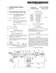
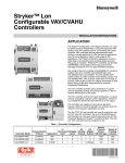
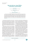
O
United States Patent [19]
[11] Patent Number:
Pearman et al.
[45]
[54]
4,637,253
1/1987 Sekimura et al. .
4,651,564
3/1987 Johnson et al. .
ELECTRONIC GAS METER
[75] Inventors: Arthur N. J. Pearman, St. Paul;
Gerald D. Hunter, L1no Lakes;
[73] Assignee:
Date of Patent:
Apr. 24, 1990
4,669,301 6/1987 Kratt et al _
4,682,496 7/1987 Miura et al. .
Michael A. Woessner, Golden
Valley; Robert E. Gilman, s1.
Michael, all Of MinnGas Research Institute, Chicago, 111.
No.: 140,714
[22] Filed:
4,918,995
OTHER PUBLICATIONS
ON SET Computer Corp., “TATTLETALE ® Model
In”, Apphcatlon Note’ PP‘ 4’ 5 and 10*“
QUARTIC Systems, Inc., “TADC-l User’s Manual”,
Manual 00174“, 1987.
Jan‘ 4’ 1988
Primary Examiner—-Herbert Goldstein
[51]
[52]
Int. Cl.5 .............................................. .. G01F 1/68
US. Cl. ............................ .. 73/861112;
Attorney, Agent. or Firm—Th0mas W. Speckman
[57]
ABSTRACT
_ [58]
Field of Search ................... .. 73/204, 861, 861.02,
An electronic compact gas meter includes a solid state
73/861.03, 861.77, 861.78, 204.11, 204.26
.
[56]
References cued
U-S- PATENT DOCUMENTS
4,093,s71
4,308,753
pled to the sensor for controlling same and providing an
output indicative of gas flow, and a digital data proces
6/1978 Plumb et al. ............... .. 73/861.03 X
4,306,457 12/1981
Fukui et al. . . . .
?ow sensor for sensing gas flow rate, data acquisition
circuits including an analog-to-digital converter cou
. . . . .. 73/861.77
SOY for receiving the gas ?OW information from the
analog-to-digital converter, processing the information
1/1982 Olson ......................... .. 73/86L13 X
and registering the volumetric gas flow reading at the
4,353,118 10/1982 Heimgartner et a1. ......... ._ 73/861 X
meter and/or transmitting the Volume flow information
Buchan """""""""""""" " 73/861 X
via RF or telephone communication lines to a remote
4,481,827 11/1924 131151.411 et a1. ....................... .. 73/861
maim
4,534,2l8 v8/1985 Ueno
4,628,743 12/1986
21 Claims, 9 Drawing Sheets
_____________________ __f"_\__ ____rlfj_\a__ i691",
as
I |
L6—°
\e2
A1
1/0
1|
1
BUFFER
:1
I
1
ECU]
1
1
TOTALIZER
E9 1
'HI g] r64 I1
A0
MUX
f~
1 '.
AID
1 1
CONV
11
1l
L63 1 i
CPU
t
T
1I
l |
READOUT
|
COUPLER
1
'42
l
ROM 1[
66
REMOTE
1
1
:1 RAM
@
l
a _______________ ___lL___:____J
US. Patent
Apr. 24, 1990
7/
////// --48
---l5
Sheet 1 of9
4,918,995
//////// _2l
////7/'////////
FIG. 2
.
FIG.2A
US. Patent
Apr. 24, 1990 .
SAMPLE
PERIOD T
tsbia ‘Hie
Sheet 2 on
4,918,995
9 US. Patent
Apr. 24, 1990
Sheet 5 of9
4,918,995 ‘
1L.
5 FIG8
5v
ids?T
US. Patent
Apr. 24, 1990
<mGE
mu-E3
Sheet 6 of9
4,918,995
US. Patent
Apr. 24, 1990
4,918,995
Sheet 8 0f 9
(3171i)
INITIALlZATlON
J:
SUBTRACT OLDEST ELEMENT
OF SAMPLE BUFFER
FROM SAMPLE ACC
L
POwER-UP
MICROBRIDGE
_
DRIVER CIRCUITRY
LOW-POWER MODE
FOR REMAINDER OF
SAMPLE PERIOD
A
NO
STABILIZATION TIME EXPIRED
E,
.
YES
FSAMPLE COUNTER = O
SAMPLE COUNTER = K
i
SAMPLE
TEMPERATURE
SENSOR
SAMPLE
FLOW SENSOR
CALCULATE
TEMPERATURE
COMPENSATION
FACTOR
POWER-DOWN
MICROBRIDGE
DRIVER CIRCUITRY
ND
NEGATIVE FLOW I?
SET TAMPER FLAG
ABSOLUTE vALUE -
HG. | |
OF FLOW
US. Patent
Aplr. 24, 1990
Sheet 9 of 9
INCREMENT SAMPLE COUNTER
l
J,
UPDATE
SAMPLE BUFFER ACCUMULATOR
COMPUTE SAMPLE BUFFER
ACCUMULATOR AVERAGE
Jr
FLOWCALC: TEMPERATURE
COMPENSATED FLOW
| FLOWACC= FLOWACC+ FLOWCALC |
FLOWACC= FLOWACC~ IOOFT3
|
INCREMENT INDEX
4,
FIG. IIA
|
4,918,995
1
4,918,995
2
The invention consists of certain novel features and
structural details hereinafter fully described, illustrated
ELECTRONIC GAS METER
in the accompanying drawings, and particularly pointed
out in the appended claims, it being understood that
BACKGROUND OF THE INVENTION
various changes in the details may be made‘without
This invention relates to apparatus for measuring 5
departing from the spirit, or sacri?cing any of the ad
usage of a commodity, and more particularly to an
vantages of the present invention.
electronic compact meter for measuring consumption
of natural gas.
Existing natural gas meters often do not meet modern
expectations for allocating costs fairly to the end users.
DESCRIPTION OF THE DRAWINGS
For the purpose of facilitating and understanding the
invention, there is illustrated in the accompanying
For example, in multi-family dwellings, it is dif?cult to
drawings a preferred embodiment thereof, from an in
cost-effectively measure gas usage for each user to pro
spection of which, when considered in connection with
mote fair billing and encourage conservation of gas. It is
the following description, the invention, its construc
often dif?cult to access the meter in multi-family dwell 15 tion and operation, and many of its advantages will be
ings for reading, inspection and maintenance. Theft and
readily understood and appreciated.
vandalism are also a signi?cant problem to the gas util
ity industry. Moreover, installation costs and space are
FIG. 1 is a perspective view of an electronic compact
gas meter provided by the present invention;
problems because of meter size and con?guration.
FIG. 2 is a vertical section view of the compact gas
It would be desirable to have an electronic compact 0 meter shown in FIG. 1;
gas meter for either interior retro?t or for new installa
FIG. .2A is a simpli?ed representation of the probe
tions that is small in size and low in cost to as to enable
assembly of the gas meter, showing the orientation of
cost-effective measurement of usage of natural gas by a
the solid state sensor relative to the duration of gas
consumer. It would also be desirable to have a gas meter
that would enable easy direct or remote reading, and 25
that is compatible with current construction materials
flow;
FIG. 3 is top plan view of the compact gas meter base
with the printed circuit boards and battery removed;
and utility operations.
FIG. 4 is a plan view of a flow sensor of the compact
gas meter provided by the present invention;
FIG. 5 is a timing diagram illustrating the operating
SUMMARY OF THE INVENTION
Therefore, it is an object of the present invention to 30 cycle for the ?ow sensing circuitry;
provide a new and improved natural gas meter.
FIG. 6 is a block diagram of the electronic signal
A further object of the invention is to provide a com
processing circuits of the compact gas meter provided
pact gas meter for either interior retro?t or for new
installations that is small in size and low in cost so as to,
by the present invention;
FIG. 7 is a schematic diagram of the drive and signal
enable cost-effective measurement of usage of natural 35 acquisition circuit of the electronic circuits of the com
gas by a consumer.
pact gas meter;
Yet another object is to provide a gas meter that
FIG. 8 is a schematic diagram of the analog-to-digital
enables easy direct or remote reading.
signal processing circuit of the electronic circuits;
Another object of the invention is to provide an elec
FIGS. 9 and 9a are a ‘schematic and partial block
tronic compact natural gas meter which is easy to in 40 diagram of the digital signal processing circuit of the
stall, reliable in operation and rugged and unobtrusive
electronic circuits;
in construction.
FIG. 10 is a functional block diagram of the gas meter
Yet another object of the invention is to provide a
electronic circuits; and,
compact natural gas meter characterized by low cost
FIG. 11 and 11A are a flow chart illustrating the
and maintenance.
45 process.
These and other objects are achieved by the present
Description of a Preferred Embodiment
invention which is provided a compact electronic gas
meter for measuring usage of natural gas or the like,
Referring to FIGS. 1-3, the compact gas meter 10
which comprises a housing having a passageway there
provided by the present invention includes a two-part
through with a gas inlet adapted for connection to a
case including a base 12 and a cover 13, a flow sensor
source of natural gas and a gas outlet adapted for con
probe assembly 14 including a solid state sensor 15, and
nection to gas utilization means, gas flow sensing means
mounted on the housing and including a solid state flow
sensor and means of locating the flow sensor in the
electronic signal processing circuits. The electronic
passageway and operable when energized for providing
55 cover 13. The compact gas meter 10 further includes an
an output signal indicative of gas flow through the
indicating device embodied as a mechanical totalizer 19
~ which provides a digital read out of the quantum of gas
circuits being carried on a pair of printed circuit boards
17 and 18 mounted on the base and enclosed within the
passageway; signal sampling means for periodically
sampling the output signal provided by the ?ow sensor
and generating a- signal representative of gas flow vol
measured by the gas meter 10.
As will be shown, the solid state sensor 15 provides a
ume over a predetermined time interval, the signal sam 60 signal output indicative of the volume of gas flow
through the gas meter. The electronic signal processing
circuits 16 sample the signal output of the ?ow sensor
15 periodically and generate a signal indicative of the
pling means de?ning operating cycles for said flow
sensor each cycle including an active period of a ?rst
duration'and an inactive period of a substantially longer
' duration, &he flow sensor being energized to provide its
output signal only during the active period of its operat
gas flow volume measured by the gas meter over a
65
given time period. This signal is applied to the totalizer
ing cycle; and indicating means controlled by the sam
pling means to provide an indication of the gas flow
19 which records a reading representative of the cumu
lative gas flow volume measured by the gas meter. The
volume measured by the gas flow sensor.
flow sensor and electronic circuits of the gas meter are
3
4,918,995
battery-powered and include low-power consuming
4
serve the battery life. For example, the electronic cir
cuits operate in an active mode during which the sam
mounting screws 35 which are received in tapped holes
36 in the base near its upstream end 23.
Referring to FIGS. 1-3, the cover 13 has a generally
trapezoidal shaped cross section with a broad base 38,
pling operation is done and a sleep mode during which
the bottom edge of which is dimensioned to correspond
elements which are operated in a manner so as to con
the flow sensor is deenergized and the electronic cir
generally to dimensions of the shoulder 26 on the upper
cuits are maintained at minimum power usage. Also, the
surface 31 of the base 12, to facilitate mounting of the
cover 13 on the base 12. A suitable sealing means 39
use of a solid state ?ow sensing device and electronic
signal processing circuits contribute to minimizing both
the size of the gas meter and its cost and expanding its
input/output capabilities, making the gas meter an at
tractive substitute for conventional gas meters either in
new installations or in retro?t applications to existing
installations.
Considering the meter 10 in more detail, the base 12 is 5
generally rectangular in shape and has a through bore
21 extending along the longitudinal axis of the base 12
de?ning a gas flow passageway through the gas meter
10. The gas meter 10 is adapted for connection to a
source of natural gas supplied to the gas meter 10 by a
suitable gas conduit or pipe represented by the dashed
line 22 in FIG. 1. The inner surface of the bore 21 at the
upstream end 23 of the gas meter is formed With‘an
internal thread 24 to facilitate coupling of the gas meter
(FIG. 2) is provided between the base and the cover to
provide a water tight seal therebetween.
As shown in FIGS. 1 and 2, the cover 13 encloses the
upper surface 31 of the base 12 thereby containing the
electronic circuits 16 therewithin. The cover 13 is se
cured to the base 12 by a closing screw 41 passing
through a lip 42 on the cover 13 into base 12. The screw
41 may be wired closed by an antitampering device 44
which is shown in FIG. 1, which threads through aper
tures 45 in projections 46 on the lip 42 of cover 13.
Referring to FIGS. 1 and 2, the cover 13 has a win
dow 48 formed therein in the top surface of the gas
meter through which is exposed to view a totalizer 19
which is mounted on the inner surface of cover 13.
In one realization of the gas meter 10 which was
constructed, the length of the base was approximately
10 to the pipe or gas conduit 22. Similarly, the down 25 6", the height of the meter from the bottom of the base
stream end 23a of the gas meter is formed with an inter
to the top of the cover was approximately 4.5” and the
width of the base was approximately 2". The base was
nal thread (not shown) to facilitate attachment thereto
of an outlet gas conduit or gas pipe which conduits the
made of a rigid material such as cast bronze and the
gas to one or more utilization devices. As will be
cover 13 was made of a rigid material such as plastic or
shown, the gas meter can sense gas flow independent of
aluminum. The physical size is slightly less than 67
cubic inches for this realization. However, the speci?c
direction, and thus, while for convention the gas meter
10 is described as having a gas inlet and a gas outlet, the
meter can measure gas ?ow in either direction between
the inlet and outlet. This affords a degree of protection
against attempts at compromising the meter by revers 35
ing its connection in the gas lines. In the exemplary‘
embodiment, the central bore 21 extends axially
through the base 12, but it is apparent that the through
bore could be offset laterally relative to the longitudinal
dimensions recited are not intended to be a limitation on
the scope of the invention, but rather to demonstrate the
substantial reduction in size of the gas meter relative to
gas meters presently in service. As indicated above, the
gasket seal member 39 provides a water tight seal be
tween the base 12 and the cover 13. Also, a suitable seal
is provided between the gas inlet and outlet conduits 22,
22a (FIG. 1) and the base 12 of the gas meter, and the
axis of the base 12.
40 ?ow sensor probe assembly 14 is designed to provide a
Referring to FIGS. 2 and 3, the upper surface 31 of
good gas seal under normal operating pressures.
the base 12 de?nes a peripheral shoulder 26, a pair of
Referring to FIGS. 2 and 3, the sensor probe assem
longitudinal channels 27 and 28. As shown in FIG. 2,
bly 14 includes a mounting portion 47, including retain
channels 27 and 28 facilitate mounting of the printed
ing collar 33, support portion 48, which extends into the
circuit boards 17 and 18 which are mounted vertically 45 through bore 21 and locates the solid state sensor 15,
within the gas meter 10 as shown in FIG. 2. The battery
within the gas flow passageway de?ned by the through
29 energizes the electronic circuits of the gas meter 10.
bore 21. The probe assembly has a connector portion 49
The battery used is one characterized by a long operat
at its upper end which extends the conductors 32 from
ing life, such as a lithium battery.
the sensor 15 to the analog circuit board 18. The solid
As shown best in FIG. 2, the base 12 has a vertically
state sensor 15, to be described in more detail, is a gener
extending bore 30 which communicates the upper sur
ally rectangular shaped member as shown in FIG. 4 and
face 31 of the base 12 with the through bore 21 and
through which extends the ?ow sensor probe assembly
extends generally coplanar with the direction of flow of
the gas through the gas passageway de?ned by through
14. The channels 27 and 28 formed in the upper surface
31 of the base 12 are sized to receive the lower edges
17a and 18a of respective circuit boards 17 and 18,
mounting the circuit boards 17 and 18 in a generally
bore 21. As illustrated in FIG. 2A, the sensor 15 has an _
vertically extending position on the upper surface of the
base 12. Circuit board 18 which carries the analog signal
processing circuit 160 is electrically connected to the
sensor probe assembly 14 by a set of conductors 32.
Printed circuit board 17, which carries the digital signal
processing circuit 161), is interconnected with the
printed circuit board 18 by suitable connectors (not
upstream end 15a and a downstream end 15b, and the
sensor is located at approximately the mid-point of the
passageway as illustrated in FIG. 2 by virtue of its
mounting at the distal end of the probe assembly mount.
The solid state sensor 15 is an immersion probe that
directly senses gas flow through the gas conducting
conduit. The principle of operation of the solid state
sensor is similar to that of a miniature hot wire anemom
eter, but differs in that the solid state sensor requires less
heating power, is more sensitive to gas flow, is more
65 rugged, exhibits a faster response time, and can be fabri
shown) and hard wiring.
The flow sensor probe assembly 14 includes a mount
cated using a batch fabrication process.
ing collar 33 in the form of an annular ring having dia
Referring to FIG. 4, which is a plan view of the solid
metrically opposed apertures 34 through which extend
state flow sensor of the flow sensor probe assembly 14,
5
4,918,995
the sensor consists of three sensors including an up
stream flow sensor 51, a downstream flow sensor 52, a
temperature sensor 53 and a heater element 54 all lo
cated on the same substrate 55. The thin film resistive
heater 54 is ?anked by the two resistive thin ?lm tem
perature sensors 51 and 52. The upstream and down
stream sensors 51 and 52 are connected to a differential
ampli?er circuit and each is driven by a current from an
individually associated constant current source. One
?ow sensor is located upstream of the heater and one is
downstream of the heater. As a result of gas flow
through the passageway of the gas meter, the sensors
respond to different quantities of heat generated by the
heater. The differential response is used as an indication
of the rate of gas flow across the bridge sensor arrange
ment de?ned by the two sensors 51 and 52 and the
associated heater 54. Flow in either direction, i.e. from
sensor 51 toward sensor 52 or from sensor 52 toward
sensor 51, can be detected, the absolute value of the
outputs will be the same in either case. In the absence of
gas ?ow, the temperatures of the two sensors 51 and 52
are substantially the same. With gas flow over the semi
conductor structure, the upstream sensor 51 is cooled
and the downstream sensor 52 is heated. This results in
an output signal which is detectable by the analog signal
processing circuit 160 (shown in FIG. 6). As will be
shown, the ?ow sensors 51 and 52 are sampled every T
6
chip or substitute 55 which temperature is not apprecia
bly different from the ambient air temperature. The
power required by heater resistor 54 to achieve 200
degrees centigrade above ambient temperature is very
small being less than 0.010 watt.
In the preferred embodiment at zero gas flow veloc
ity, thermal conduction from heater resistor grid 54,
largely through the surrounding air space heats the
identical temperature sensing resistor grids 51 and 52 to
an average temperature of about 140 degrees centigrade
or about 70 percent of the temperature elevation of
heater element 54. In the preferred embodiment illus
trated, sensor grids 51 and 52 are precisely symmetri
cally located with respect to heater grid 54 so that at
zero gas ?ow they have identical temperatures and have
no difference between their resistances. Consequently, a
small probe current through both sensor resistances 51
and 52 will develop no voltage difference at zero gas
flow velocity.
With gas flow present, upstream resistor sensor 51
will be cooled by the transportation of heat away from
sensor 51 toward heater resistor grid 54, whereas the
downstream sensor 52 will be heated by transportation
of heat toward the sensor 52 from heat resistor grid 54.
25 Consequently, a resistance difference between sensor
resistances 51 and 52 will be present with a correspond
ing difference in voltage drop which is a measure of the
gas flow. Typical unampli?ed voltage differences can
seconds and the temperature sensor 53 is sampled every
be as high as 0.1 volt at a 1500 feet per minute ?ow
kT seconds. The temperature sensor is used to compen
sate the gas meter 10 for temperature variations. The 30 velocity.
In the preferred operation of the solid state flow
sampling period T is illustrated in FIG. 5 and will be
described in detail hereinafter.
Sampling of the state of the ?ow sensors 51 and 52
and the temperature sensor 53, as well as the energiza
tion of the sensors and the heater 54 is provided by the
Other arrangements are also possible including arrange
electronic circuits 16 of the gas meter 10 which are
ments which would operate the two temperature sen~
sensor, sensors 51 and 52 are driven with a constant
current such that temperature ?eld changes can be
sensed under flow conditions as previously described.
sors in a constant voltage mode, a constant temperature
shown in block diagram form in FIG. 6.
Referring to FIG. 6, the electronic circuits 16 include
(constant resistanpe) mode, a constant power mode, or
any mode that produces a differential signal.
an analog-to-digital signal processing circuit 160 and a
digital signal processing circuit 16b, which are mounted 40 Referring now to FIG. 6, the temperature sensors 51
and 52 of the solid state flow sensor 15 are connected in
on the two printed circuit boards (FIG. 2), 17 and 18,
arms 70 and 70a of a bridge network, the sensors 51 and
respectively. The structure and function of the analog
to-digital signal processing circuit 16a and digital signal
processing circuit 16b will be described hereinafter.
52 being energized by current supplied by respective
constant current sources 71 and 72. The heater resistor
Brie?y, the analog-to-digltal signal processing circuit
45 54 is energized by a further constant current source 74
16a includes a drive and signal acquisition circuit 61
(FIG. 7), a multiplexing circuit 62 (FIG. 8), and an
and the reference temperature sensor 53 is driven by a
constant current source 73a. The temperature sensor’s
analog-to-digital converter 63 (FIG. 8). The digital
signal processing circuit 16b (FIG. 9) includes a micro
other bridge leg is driven by constant current source
73b. The ?ve constant current sources 71, 72, 73a, 73b
and 74 are not continuously energized but are only
processor system which includes a central processing
unit CPU 64, an input/output buffer 65, memory cir
cuits 66, and a real time clock 67.
Considering the ?ow sensor 15 (FIG. 6) in more
detail, the ?ow sensor corresponds to the solid state
sensor described in U.S. Pat. No. 4,651,564, and the
energized during a sampling interval de?ned by the
central processing unit 64 as will be shown.
The junction temperature sensors 51 and 52 are con
construction, con?guration and operation of the solid
nected to the inverting and non-inverting inputs, re
spectively of a differential ampli?er 75, the output of
which is extended to the multiplexer 62. Reference
state sensor is described in detail in the US. Pat. No.
temperature sensor 53 of sensor 15 and the temperature
sensor’s other bridge leg, which includes resistor 53a,
are connected to the inverting and non-inverting inputs
Brie?y, with reference to FIG. 4, the How sensor 15 60 respectively of differential ampli?er 76, the output of
which is extended to multiplexer 62. The multiplexer
comprises a pair of identical thin ?lm heat sensors 51
4,651,564, and accordingly will not be described in
detail herein.
circuit 62 operates under the control of the central
processing unit 64 to selectively extend to the analog
to-digital converter circuit 63 the outputs of the differ
the base. Sensors 51 and 52 are disposed on opposite
65 ential amplifiers 75 and 76, representing the flow rate of
sides of heater 56.
The heater resistor grid 54 operates at a preferred
_the gas measured by the meter 10 and the reference
constant average temperature difference of 200 degrees
temperature provided by temperature sensor 53. As
centigrade elevated above the temperature of silicon
indicated, the reference temperature reading is sampled
and 52, a thin ?lm heater 54 and a base or substrate 55
supporting the sensors and heater out of contact with
7
4,918,995
8
Referring to FIG. 8, the analog-to-digital converter
less frequently than the flow rate signal provided by the
differential ampli?er 75.
63 includes a programmable A/D converter circuit 91,
a two-bit counter 92 de?ned by data latches 93 and 94
The analog-to-digital converter circuit 63 receives
the output extended thereto from the multiplexer circuit
and associated output logic gates 95-98, a power switch
62 and converts this output signal into a digital signal,
which signal is applied to the central processing unit 64.
The central processing unit 64 operates under program
control to execute the operations necessary to effect the
circuit 99 and an inverting voltage source 100 which
converts +5 VDC to —5 VDC for the programmable
analog converter 91. The multiplex circuit 62 is associ
ated with the analog-to-digital converter circuit 63 and
circuits 62 and 63 comprise an integrating converter
analog processor such as the type commercially avail
able from Quartic Systems, Inc. as the Model TADC-l
periodic readout of the information provided by the
flow sensor, to enable the analog circuits to receive this
information, to read this information from the output of
the analog-to-digital converter 63 and to calculate the
A/D converter.
The analog-to-digital converter features variable
length conversions, adjustable from 9 bit resolution to
16 bit resolution by programming of the device by the
user. The analog-to-digital circuit 63 is characterized by
flow rate. The central processing unit 64 through input
/output drivers 65 causes the current meter flow rate
information to be registered on the totalizer 19 and
supplies suitable commands to the analog circuits 16a to
variable power consumption, typically 25 mw when on,
0 mw when off. The compact gas meter 10 operates at
effect the sampling procedure. The central processing
unit 64 also supplies information or data to a remote
transmitting unit 20 enabling meter reading information
and other information to be transmitted to a remote
16 bit resolution. The A/D input voltage is scaled so
20 that 2.5 VDC provides a full scale reading of 200 cubic
feet per hour. Therefore, 16 bits provides 65,536 levels
interrogation station, and to receive information and
commands from such remote interrogation station to
effect or alter the operation of the electronic circuits of
of resolution or 0.003 CHF/level. This resolution is
more than adequate at the lower flow rates where the
the gas meter 10.
25
FIG. 7 is a schematic circuit diagram of the drive and
signal acquisition circuits 61 that interface the solid state
sensor 15 with the rest of the analog-to-digital signal
processing circuit 160. Each of the ?ve constant current
sources 71, 72, 73a, 73b and 74 are comprised of an
output is nearly linear with flow.
Because the multiplexer circuit 62 and the analog-to
digital converter 63 comprise a commercially available
unit as mentioned above, these circuits will not be de
scribed in detail. Brie?y, the multiplexer circuit 62 com
prises the type 4051 8 input multiplexer having two of
its inputs labeled FLOW and TEMP connected to the
operational ampli?er 81, 82, 83, 87 and 84, respectively,
outputs of ampli?ers 75 and 76, respectively of the sig
nal acquisition circuit (FIG. 7). The multiplexer circuit
each having respective resistive networks which pro
vide the desired current levels. A circuit 78 provides a
stable 2.5 VDC reference voltage for the ?ve opera
tional ampli?ers current sources that drive the tempera»
ture bridge, the sensor bridge and the heater of the solid
includes three input select inputs A, B, and C, which are
selectable by signals applied thereto by over control
output lines D1~D3 of the central processor unit (FIG.
9) as will be shown.
The two-bit counter comprises a pair of data latches
93 and 94 connected in tandem with each connected for
operation as a pulse divider to step the analog‘to-digital
state sensor 15. Ampli?er 88 is a voltage follower that
provides a high to low impedance transfer function
between the 2.5 VDC reference and the ?ve constant
current source inputs.
converter through four conversion modes. The input
Ampli?ers 83 and 87 are the constant current source
stage data latch 93 has its clock input connected to a
control output D12 of the central processing unit to
drives for the onboard temperature sensor 53. Ampli?er
83 sources 100 microamps through the temperature
sensor 53. Ampli?er 87 current sources 100 microamps
receive a clocking pulse therefrom. The false output of
latch 93 is connected to the clock input of data latch 94.
through the ambient temperature bridge reference leg
45 The true outputs of the two data latches are combined
resistance 53a. The temperature bridge current is set by
resistors R17 and R21. The temperature bridge output is
applied to an input of ampli?er 76, the output of which
is connected via signal channel A1 to the multiplexer
by NAND gate 95 which is connected to an invertor
circuit 62 (FIG. 6).
de?ned by NAND gate 96. The output of gate 96 is
connected as one input to NAND gate 98, a second
input of which is connected to an invertor 97. Invertor
50
The ?ow sensor de?nes three sensor elements includ
ing upstream sensor 51, downstream sensor 52 and
heater 54. These elements are driven by respective con
stant current sources 71, 72 and 74 having associated
operational ampli?ers 81, 82 and 84, respectively. The
two ?ow sensors are operated with constant currents of
400 microamps each. The heater 54 is operated at a
constant current the current level being set by resistor
R6. Flow sensor current for sensor 51 is 'set by resistor
R2. The sensor current for the downstream sensor 52 is 60
97 has its input connected to the output COMP of the
programmable analog converter 91. Output COMP is
also connected to a signal input D0 of the central pro
cessing unit and the output of gate 98 is connected to a
further input D13 of the central processing unit. Gates
94-98 provide the necessary logic to set input D13
appropriately for transmitting the result of the conver
sion to the central processing unit input D0 signals the
polarity of the sampled analog voltage to the central
processing unit.
The central processing unit also controls the opera
tion of the analog-to-digital converter to the extent that
resistor R25.
an output on control line D6 effects reset (prior to each
The output of the flow sensor bridge is ampli?ed by
conversion sequence) of the two-bit counter 92. An
ampli?er 75. The gain for ampli?er 75 is set by resistor
output on control line D10 enables power switch circuit
R1. The signal output of the ampli?er is ?ltered by a 65 99 to apply power at +V to the analog-to-cligital cir
set by resistor R10 and bridge balance is provided by
?lter network comprised of resistor R30 and capacitor
C10 and passed through a second signal channel A0 of
cuits and to the flow sensor.
the analog multiplexer.
processing circuits provide the control signals for the
Referring now to FIGS. 9 and 9A, the digital signal
4,918,995
10
analog~to-digital converter, as indicated, process data
incoming from the ?ow of sensor 15, including calculat
ing ?ow rates and updating the totalizer. The process
ing unit may transmit information to a remotely located
may comprise the microprocessor system commercially
interrogate station (not shown) and receive information
for example. Output _D4 of the central processing unit
and commands therefrom via an interface network 100
increments the totalizer 19.
Referring to FIG. 10,. which is a functional block
diagram of the electronic circuits of the gas meter 10,
the digital circuits 16b control the application of dc
power to the sensor 15 and the analog-to-digital circuit
160, central processing unit of the digital circuits pro
viding an output on line D10 for enabling power switch
99 which responsively extends Vdc to the sensor 15 and
the analog circuits 16a. The central processing unit
controls the analog circuits 160 over control lines
D1~D3, D6 and D12 and receives outputs from the
analog circuits 16a over lines D0 and D13. The signal
outputs of the sensor 15 is extended to the analog cir
available as the Model III Tattletale commercially
available from Onset Computer Corporation.
The totalizer 19 may be the HECON series GO634,
using RF signaling or telephone line communication as
is known in the art.
The digital signal processing circuit includes the cen
tral processing unit 64, memory circuits 66, the remote
interface network 65, and a real time clock 67. The
central processor includes 16 address inputs connected
over an address bus 111 to the memory circuits 66, eight
data outputs D0-D8 which are connected via a data bus
as inputs to the memory 66, and fourteen control/input
ports D0-D13 which supply information to and receive
information from the analog-to-digital converter circuit
16a.
As indicated, the central processing unit 64 provides
cuits 160 over lines A0 and A1, which outputs are the
the control signals for the analog-to-digital converter
circuits. The control line functions are shown in Table
I along with the default functions for these lines.
TABLE I
Line
Default
Use
D0
Dl,D2,D3
D4
none
none
none
POL
ENA
D6
D10
none
none
RST
PWR
input for polarity detection
selects analog MUX channel
drive signal for
accumulator
output for system reset
output for power control
D12
Dl3
TONE
PERIOD
CLK
EDC
output for clocking mode
input for end-of-conversion
Use
?ow and reference temperature, respectively.
Control outputs D1-D3 control the multiplexer cir
cuit 62 to provide selection for the signal on line A0 or
line A1 for the analog circuits. Control output D6 resets
the analog-to-digital converter 63. Control output D12
25
sequences the analog-to-digital converter. Input D10
enables the central processing unit to detect the polarity
of the analog signal being processed and input signals
D13 indicates end of conversion operation for the ana
log-to-digital converter.
The central processing unit operates under program
control to ?rst call a power up routine to energize the
analog circuits 16a and the sensor 15. The central pro
cessing unit then calls a conversion routine and controls
Referring to FIG. 9, the central ‘processing unit 64
provides the following major functions for the compact
the analog-to-digital converter in taking a reading of the
sensor ?ow value and reference temperature value and
returns the results of the conversion to the central pro
gas meter 10:
1. All control functions for the analog-to-digital con~
verter;
cessing unit. The central processing unit then calls a
power down routine to deenergize the analog circuits
16a and the sensor 15. Finally, the central processing
_
2. Control of power on-time to the analog-to-digital
converter and sensor circuits including de?ning a sleep
unit increments the totalizer 19 to re?ect the most re
mode;
cent gas flow reading.
The procedure by which the sensor output is sampled
3. Reads the output on the analog-to-digital converter
for flow rate and ambient temperature and computes
the necessary correction factors required to correct for
is dependent upon two parameters. The ?rst is the sam
45 ple period, T, which dictates the frequency of the sam
flow, temperature or pressure if necessary; and
pling. The second is the number of samples, k, which
4. Keeps track of accumulated flow and outputs to
are integrated when computing the current volumetric
the totalizer 19 or other media such as RF or telephone
?ow rate.
modem for remote readout mode via the interface net
Referring to FIG. 4, in the exemplary embodiment,
work 100.
the sampling period T is one second. Voltage V1 is a
For the digital signal processing circuits shown in
?xed offset voltage set by resistor l226 (FIG. 7) at the
input of ampli?er 76. The voltage V2 is the sensor volt
FIGS. 9 and 9A, circuits 121 (U2) and 122 (U10) pro
vide encoding for chip selection. Circuit 123 (U3) is a
32K by 8 bit Eprom memory for program storage. Cir
cuit 124 (U4) provides 32K by 8 bit static RAM for
program development and storage. Circuits 125 (US)
and 126 (U6) provide 32K by 8 bit static RAM data
storage. Circuits 127 (U7) and 128 (U12) interface the
age response. This response varies as a function of the
?ow rate past the sensor. This signal is ampli?ed by
ampli?er 75 prior to application to the analog-to-digital
converter. The total conversion time is typically about
112 ms and includes a settling time is of about 60 ms, and
integration time ti of about 24 ms for a l6-bit conver
central processing unit 64 with a RS 232 mode to enable
down or up loading of data or for interfacing the central
processing unit 64 with another computer.
Circuit 67 (U9) de?nes a real time clock circuit which
provides real time data for use by the central processing
unit in specifying the time of occurrence of gas flow,
etc.
sion, and a deintegration time td which varies propor
60
tionally to the analog-to-digital converter input voltage.
The balance of the cycle time is the data processing
period. A running average of a plurality of raw signal
samples is used to compute the volumetric ?ow reading
which is used to update the flow counter. A similar
The central processing unit 64 is an 8 bit CMOS 65 A/D conversion is made on the output of the tempera
ture sensor, but is done only once every 32 samples.
More speci?cally, a running average of the most
recent “k” samples of the differential responses is main
microcomputer such as the type 63 AO3Y commercially
available from Hitachi. Moreover, the entire digital
signal processing circuits illustrated in FIGS. 9 and 9A,
11
4,918,995
12
tained by the meter. The “k” sample values are stored in
the data memory, the set of sample values being up
dated each sampling by substituting the current or
circuits are shut down after each sampling sequence.
Reading the temperature less frequently does not affect
accuracy because the temperature will not slew as fast
“newest” sample value for the “oldest” sample value.
The average of this updated set of “k” samples is used as
the current reading of gas flow. This average is used to
compute, using a table look-up derived from meter
as the flow data will.
calibration data, the corresponding volumetric flow
The running average is used in order to account for
noise which could otherwise adversely affect the gas
flow readings obtained. The central processing unit
de?nes a “sliding window” which basically comprises a
running average of the data taken over a given interval,
or a number of data samplings, for example, thirty-two.
With each sampling operation, the oldest value is de
leted and the newest value is added and averaged with
rate for the current sample period. Various methods for
obtaining calibration data are known in the art. The
flow rate sample is compensated for ambient tempera
ture variations using a temperature compensation de
rived from the last sample output obtained from the
the previous 31 values. This running average of thirty
reference temperature sensor 53. The compensated
two readings may vary relative to the direction of
value is multiplied by a time value T yielding the vol 15 change of the flow rate. Data obtained for each reading
ume of gas usage for the current sample period. This
is averaged into this running average and used as the
volume measurement is then added to the meter’s flow
current reading. A test is made prior to this averaging
accumulation register in memory. This register is then
and if the data does not compared favorably, then the
compared with a flow resolution register established for
latest obtained data is ignored. Thus, for example, if the
the meter and the mechanical totalizer 19 is incre 20 reading from one sample to the next sample changes
mented each time a given flow volume is measured. By
from a certain value to zero, for example, it can be
way of example, the ?ow resolution register value is set
assumed that noise or some other error has created this
at 100 cubic feet (cf), the mechanical totalizer 19 is
change and the reading is ignored. This comparison
stepped each time that the flow accumulation register
reduces the effect of the bad reading and eliminates or
count equals or exceeds this value. The reading stored 25
substantially
reduces the susceptibility to noise.
by the accumulation register is reduced by 100 of each
Referring to FIGS. 11 and 11A, there is illustrated a
time that the totalizer is incremented.
process ?ow chart for the central processing unit. Upon
In the exemplary embodiment, a ?xed sample period
is used in the sampling of the sensor for the gas meter - startup, the program ?rst executes an initialization rou
10. It is possible to make the sampling period, T, a func 30 tine. After initialization, the ?rst step in the program is
to adjust the running average of the “sliding window”
tion of the ?ow rate and the acceleration of the ?ow
by
subtracting the oldest element of the sample buffer
rate, i.e., rate of change, as measured by the meter.
from the sample accumulator. Then the central process
When a variable sampling rate is used, the sampling rate
ing unit enables power circuit 99 (FIG. 8) to energize
is set higher during high flow rates to decrease error
and set lower during low flow rates, where the accu 35 the analog circuitry and the flow sensor, and after the
stabilization time has expired, a test is made to deter
racy speci?cation is more lenient, to decrease power
mine if it is time to read the temperature sensor. If so,
consumption. On a time scale of one year depending on
the sample counter is set to zero, the temperature sensor
the environment, the average flow rate is likely to fall
into the lower flow rate range, and thus use of a variable
sampling rate can be used to reduce power consump
tion. Also, when the acceleration of the ?ow rate is low,
i.e. not changing signi?cantly, sampling can be carried
out on a lower frequency basis whereas when the accel
output is sampled and the temperature compensation
factor is calculated and stored as an updated tempera
ture compensation factor. Then the program returns to
the main ?ow. At this point, or if the test indicated that
it was not time to sample the temperature sensor, the
program continues and samples the flow sensor. After
eration is high, a faster sampling rate is employed.
With reference to FIGS. 6 and 10, the central pro 45 the sampling operation is completed, the analog-to-digi
tal circuits and the flow sensor 15 are deenergized.
cessing unit 64 operates under program control to read
Then a test is made to determine if the direction of the
the information provided by the flow sensor 15, via the
flow is negative, indicative of tampering with the meter
analog-to-digital converter, update the flow reading
by reversing its connections to the gas pipe link. If the
information stored by the central processing unit and to
flow rate signal is negative, then the absolute value of
periodically update the current gas flow volume read
the flow rate signal is used n the flow rate calculation
ing and update the state of the totalizer 19. The central
and a tamper flag is set.
processing unit de?nes a sleep mode and periodically
Then the sample counter is incremented and the sam
energizes the ?ow sensor 15 and the analog-to-digital
ple buffer accumulator is updated. The sample accumu
circuit 160 for a brief sampling interval, maintaining
these circuits energized only during the sampling inter
55 lator average, including the current measurement sam
val.
ple and the precious 31 samples, is computed and the
In the exemplary embodiment, the information is read
once every second. First, the central processing unit
enables power switch 99 (FIG. 8) to apply power to the
flow sensor 15, and the analog-to-digital circuit 16a,
including the analog multiplexing circuit 62 and the
flow rate is calculated using the most recent tempera
ture compensation flow factor. Then the current flow
rate is added to the accumulated flow rate stored in the
flow rate register and a test is made to determine if the
flow rate register count is greater than or equal to a
value corresponding to 100 cubic feet. If not, the pro
analog-toédigital converter circuit 63. The central pro
cessing unit then de?nes a stabilizing period ts to enable
gram loops back to the beginning, remaining in low
the ?ow sensor heater to stabilize. Then the processor
power mode for the remainder of the sample period. If
reads the gas flow rate sensor. As indicated, the temper 65 the flow accumulator value is equal to or greater than
ature sensor 53 is read at a slower rate, or that is, less
the resolution value, then the flow register value is
frequently, than differential output of the flow sensors
51 and 52 to conserve time and thus power because the
adjusted to subtract one unit (100 cf ) and the totalizer
19 is incremented by one.
13
4,918,995
The central processing unit continues under program
control to transfer the ?ow sensor and the analog cir
cuits to the power up mode, to sample the output signals
provided by the ?ow (and temperature) sensors and
14
6. A gas ?ow meter according to claim 1, wherein
said signal sampling means includes sensor, signal de
tecting means for detecting said output signal, and sig
nal processing means connected to said signal detecting
means and responsive to said output signal for generat- _
store the information before deactivating the flow sen
ing a gas flow volume output signal indicative of gas
sor and the analog circuits. The reading is stored in
flow volume over a given time interval and applying
memory and thus stored information is used to incre
said gas ?ow volume output signal to said indicating
ment the mechanical totalizer as each 100 of unit of gas
means.
?ow is measured.
7. A gas flow meter according to claim 6, wherein
10
We claim:
said signal processing means averages the values of
1. A compact gas meter for measuring usage of natu
ral gas or the like by a consumer over a time interval to
enable
of the consumer by a utility, comprising:
a housing having a passageway therethrough with a gas
inlet adapted for connection to a source of natural gas
provided by the utility and a gas outlet adapted for
connection to gas utilization means of the consumer, gas
flow sensing means mounted on said housing and in
cluding a solid state ?ow sensor having a substrate
bearing a thin film heating element and ?rst and second
thin ?lm temperature sensing elements ?anking said
heating element, and means locating said flow sensor in
said passageway to directly sense gas flow through said
passageway, said ?ow sensor being oriented to extend
generally coplanar with the direction of flow of the gas
through said passageway, with one of said temperature
sensing elements located upstream of the gas flow
through said passageway and the other one of said tem
perature sensing elements located downstream of the
gas flow, said ?ow sensor being operable when ener
gized to provide an output signal indicative of gas flow
rate through said passageway, signal processing circuit
means‘ mounted within said housing and electrically
connected to said ?ow sensor, said signal processing
circuit means including signal sampling means for peri
odically sampling the output signal provided by said
successive output signals of said ?ow sensor over a time
interval in generating said gas flow volume output sig
nal.
8. A gas flow meter according to claim 7, wherein
said signal processing means includes signal accumulat
ing means for accumulating signals corresponding to
the gas flow volumes represented by a series of said
output signals of said flow sensor and the average value
of the gas flow volume represented by said accumulated
output signals accumulated by said signal accumulating
means, and wherein for each successive sampling per
iod, said signal processing means adds to said accumu
lated signals a signal corresponding to the value of the
gas ?ow volume represented by the current output
signal and subtracts from said accumulated signals a
signal corresponding to the value of the gas ?ow vol
ume of the ?rst of the series of the accumulated output
signals.
9. A gas flow meter according to claim 6, wherein
said ?ow sensor includes reference sensor means pro
viding a reference output signal indicative of ambient
temperature, said detecting means including means for
detecting said reference signal, and said signal process
35 ing means responding to said reference signal to com
pensate the flow rate output signal for changes in ambi
ent temperature relative to a preselected value.
10. A gas meter according to claim 9, wherein said
?ow sensor during sampling periods and generating a
signal representative of gas flow volume over a prede
signal processing means samples said signal ‘output of
termined time interval, power switch means responsive 40 said reference sensor means at a rate substantially less
to said signal sampling means for energizing said flow
than the sampling rate for said gas flow sensor.
sensor during said sampling periods, said signal sam
11. A gas meter according to claim 6, wherein said
pling means de?ning operating cycles for said power
signal sampling means is adapted for energization by a
switch means, each operating cycle including an active
battery and wherein said power switch means connects
period of a given duration and an inactive period of a 45 said flow sensor to the battery during said active peri
substantially longer duration, said power switch means
ods.
energizing said flow sensor enabling said flow sensor to
12. A compact gas meter associated with a building
for measuring usage of natural gas or the like, there
of each operating cycle, and indicating means con
within by a consumer, said gas meter comprising: iridi
trolled by said sampling means to provide an indication 50 cating means for providing‘ an indication of gas flow
of the gas flow volume measured by the gas flow sensor.
volume over a time interval to enable billing of the
2. A gas meter according to claim 1, wherein said
consumer by a utility, a housing having a passageway
signal sampling means samples said output signal of said
therethrough with a gas inlet adapted for connection to
flow sensor at a ?xed sampling rate.
a source of natural gas provided by the utility and a gas
3. A gas meter according to claim 2, wherein said
outlet adapted for connection to gas utilization means of
provide its output signal only during the active period
signal sampling means samples said output signal a plu
rality of times during the active period of each operat
ing cycle.
the consumer, gas flow sensing means mounted on said
housing and including a solid state flow sensor and
means locating said flow sensor in said passageway to
4. A gas flow meter according to claim 1, wherein
directly sense gas ?ow through said passageway, said
?ow sensor being oriented to extend generally coplanar
for sampling said output signal of said ?ow sensor as a
with the direction of flow of gas through said passage
function corresponding to the flow rate of gas through
way, said flow sensor being operable when energized to
said passageway for a given time duration.
provide an output signal indicative of gas flow through
5. A gas flow meter according to claim 1, wherein
said passageway, signal processing circuit means
said signal sampling means de?nes the sampling period 65 mounted within said housing and electrically connected
for sampling said output signal of said flow sensor as a
to said flow sensor, said signal processing circuit means
function corresponding to the rate of change of the flow
including signal sampling means for periodically sam
said signal sampling means de?nes the sampling period
rate for a given time duration.
pling the output signal provided by said flow sensor and
15
4,918,995
16
generating a signal representative of gas flow volume
tially longer duration, said power switch means energiz
over a predetermined time interval, power switch
means responsive to said signal sampling means for
ing said circuit means and said ?ow sensor only during
energizing said flow sensor during said sampling period;
said signal sampling means de?ning operating cycles for
means controlled by said signal sampling means to pro
vide an indication of the gas ?ow volume measured by
said power switch means, each operating cycle includ
the gas flow sensor.
the active period of each operating cycle, and indicating
ing an active period of a given duration and an inactive
17. A gas meter according to claim 16, wherein said
period of a substantially longer duration, said power
flow sensor comprises a reference temperature sensor
switch means energizing said ?ow sensor enabling said
for providing a reference output signal indicative of
ambient temperature, said signal sampling means in
cluding means for detecting said reference output signal
and for compensating said output signal of said flow
?ow sensor to provide its output signal only during the
active period of each operating cycle, said indicating
means being controlled by said sampling means to pro
vide an indication of the gas flow volume measured by
sensor for variations in ambient temperature from a
the gas ?ow sensor.
given value.
13. A gas meter according to claim 12, wherein said
18. A gas meter according to claim 17, wherein said
signal sampling means includes signal detecting means
signal sampling means comprises signal multiplexing
for detecting said output signal, and signal processing
means, analog-to-digital converter means and processor
means connected to said signal detecting means and
means, said signal multiplexing means being controlled
responsive to said output signal for generating a gas
flow volume output signal indicative of gas flow vol
by said processor means to selectively extend said flow
signal and said reference signal to said analog-to-digital
ume over a given time interval and applying said gas
converter means, said analog-to-digital converter means
flow volume signal to said indicating means.
14. A gas meter according to claim 13, wherein said
signal processing means averages the values of output
signals provided over a number of successive sampling
intervals to provide an average output signal for use in
being controlled by said processor means to convert
analog signals extended thereto to digital signals, said
processor means using said digital signals to compute
25
gas flow volume signals for application to said indicat
ing means.
19, A gas meter according to claim 16, wherein said
calculating the gas volume flow volume output signal
for each sampling interval.
housing comprises a base portion having said passage
15. A gas meter according to claim 14, wherein said
way formed therethrough and a cover portion con
signal processing means adjusts said average output
natural gas or the like by a consumer over a time inter
structed and arranged for mounting on said base portion
de?ning a compartment, said signal processing circuit
means being mounted within said compartment, and
said gas ?ow sensing means including a probe assembly,
said base portion having a passageway communicating
said compartment with said passageway in said base
val to enable billing of the consumer by a utility, com
portion, said probe assembly being mounted in said
prising: a housing having a passageway therethrough
aperture with one end carrying said ?ow sensor located
with a gas inlet adapted for connection to a source of
in said passageway and another end extending adjacent
to said signal sampling means facilitating connection of
the signal output of said flow sensor to a signal input of
said signal sampling means.
20. A compact gas meter for measuring usage of
signal in accordance with calibration data for the gas
meter prior to applying the averaged output signal to
the indicating means.
16. A compact gas meter for measuring usage of
natural gas provided by the ulility and a gas outlet
adapted for connection to gas utilization means of the 40
consumer, gas flow sensing means mounted on said
housing and including a solid state ?ow sensor and
means locating said flow sensor in said passageway to
natural gas or the like by a consumer over a time inter
val to enable billing of the consumer by a utility, com
directly sense gas flow through said passageway, said
gas ?ow sensor including a ?rst thin ?lm temperature 45 prising: a housing having a base portion and a cover
sensing element and a second thin ?lm temperature
sensing element located downstream of said ?rst tem
perature sensing element and a thin ?lm heater element
located between said ?rst and second'temperature sens
ing elements, said flow sensor being oriented to extend
generally coplanar with the direction of flow of gas
through said passageway, circuit means connecting said
?rst and second temperature sensing elements in a bal
anced bridge con?guration to enable said flow sensor
when energized to provide an output signal indicative
of gas flow through said passageway signal processing
circuit means mounted within said housing and electri
cally connected to said flow sensor, said signal process
ing circuit means including signal sampling means for
periodically sampling the output signal provided by said
portion, gas flow sensing means, signal sampling means,
and indicating means, said base portion having a pas
sageway therethrough with a gas inlet adapted for con
nection to a source of natural gas provided by the utility
and a gas outlet adapted for connection to gas utiliza
tion means of the consumer, and said base portion hav
ing an aperture communicating said passageway with
an upper surface of said base portion, said gas ?ow
sensing means including a solid state flow sensor having
?rst and second thin ?lm heat sensor elements and sup
port means supporting said sensor elements, and mount
ing means mounted on said base portion in said aperture
thereof, locating said flow sensor in said passageway
with one of said elements positioned upstream of the
other element and with said sensor located approxi
flow sensor and generating a signal representative of gas
flow volume over a predetermined time interval, power
switch means responsive to said signal sampling means
for energizing said circuit means and said flow sensor
mately at the mid-point of said passageway to directly
of a given duration and an inactive period of a substan~
7 means being operable to periodically sample the output
sense gas ?ow through said passageway, said flow sen
sor being operable when energized to provide an output
signal indicative of gas flow in either direction through
during said sampling periods, said signal sampling 65 said passageway, said signal sampling means being
means de?ning operating cycles for said power switch
mounted on said upper surface of said base portion and
means, each operating cycle including an active period
connected to said flow sensor, said signal sampling
17
4,918,995
.
18
,
temperature sensing means, circuit means connecting
signal provided by said flow sensor and generate a sig
nal representative of gas ?ow volume over a predeter
said ?rst and second temperature sensing means in a
mined time interval, said signal sampling means de?ning
operating cycles for said ?ow sensor, each operating
balanced bridge con?guration to enable said flow sen
sor when energized to provide an output signal indica
tive of gas ?ow through said passageway, signal sam
cycle including an active period of a given duration and
an inactive period of a substantially longer duration,
said flow sensor being energized to provide its output
pling means for periodically sampling the output signal
provided by said ?ow sensor and generating a signal
representative of gas flow volume over a predetermined
time interval, said signal sampling means including pro
signal only during the active period of its operating
cycle, said cover portion adapted for mounting on said
base portion enclosing said ?ow sensing means, said
cessor means and analog-to-digital converter means
signal sampling means, and said indicating means there
within, said cover portion having a window therein,
and said indicating means being mounted adjacent to
said window and exposed to view therethrough and
being controlled by said sampling means to provide an
indication of the gas flow volume measured by the gas
flow sensor.
21. A compact gas meter for measuring usage of
enabled by said processor means to convert analog
signals provided by said flow sensor to digital signals
for use by said processor means in calculating gas flow
volume signals, said processor means obtaining the ab
solute value of said analog signals for calculating said
gas flow volume signals to thereby enable measurement
of gas ?ow through said passageway in either direction,
power switch means responsive to said signal sampling
natural gas or the like by a consumer over a time inter
means for energizing said circuit means and said flow
val to enable billing of the consumer by a utility, com
sensor during said sampling periods, said signal sam
pling means de?ning operating cycles for said power
prising: a housing having a passageway therethrough
switch means, each operating cycle including an active
period of a given duration and an inactive period of a
with a gas inlet adapted for connection to a source of
natural gas and a gas outlet adapted for connection to
gas utilization means, gas flow sensing means mounted
on said housing and including a solid state flow sensor
and means locating said flow sensor in said passageway,
substantially longer duration, said power switch means
energizing said circuit means and said ?ow sensor only
during the active period of each operating cycle; and
indicating means controlled by said signal sampling
said gas flow sensor including ?rst temperature sensing
means to provide an indication of the gas ?ow volume
measured by the gas ?ow sensor.
means and second temperature sensing means located
downstream of said ?rst temperature sensing means and
=0!
heater means located between said ?rst and second
35
45
55
65
*
*
*
*