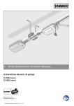
1
Construction Services Company s.a.r.l Flight Simulator Facility Rayak Air Base - Lebanon W912ER-10-C-0030 Cleared For Construction Design Phase (100% Design Phase) Annex 2 Electrical Specifications May 13, 2011 1 Zalka - Cite Moussa - Bloc A - 8 th Floor - P.O. Box : 70803 Beirut-Lebanon Tel: +961 1 897625/238 / Cell: +961 3 317100- Fax: +961 1 884307- E-mail: [email protected] FFLLIIG GH HTT S SIIM MU ULLA ATTO OR R FFA AC CIILLIITTY Y R RA AY YA AK KA AIIR RB BA AS SE E -- LLE EB BA AN NO ON N SPECIFICATIONS ELECTRICAL WORKS DIVISION 13 & 16 - ELECTRICAL DESIGN ENGINEER Submitted by Specifier DEP CSC Najat Francis EGN CONSULTANTS / WTA UH1H Flight Simulator Facility Rayak Air Base - Lebanon Specifications Electrical Works ELECTRICAL SPECIFICATION INDEX DIVISION 13 – Electrical SECTION 13100 LIGHTNING PROTECTION SECTION 13852 DIGITAL, ADDRESSABLE FIRE ALARM SYSTEM DIVISION 16 - Electrical SECTION 16010 BASIC ELECTRICAL REQUIREMENTS SECTION 16060 GROUNDING AND BONDING SECTION 16115 MAIN DISTRIBUTION BOARDS COVERING 16441 SWITCH BOARDS 16410 ENCLOSED SWITCHES & CIRCUIT BREAKERS SECTION 16116 DISTRIBUTION, SUBDISTRIBUTION AND FINAL BRANCH CIRCUIT PANELBOARDS. COVERING 16442 PANEL BOARDS SECTION 16120 CONDUCTORS AND CABLES SECTION 16130 RACEWAYS & BOXES SECTION 16140 WIRING DEVICES SECTION 16145 LIGHTING CONTROL DEVICES SECTION 16231 PACKAGED ENGINE GENERATOR SECTION 16331 GENERAL LIGHTING INSTALLATIONS COVERING 16511 INTERIOR LIGHTING 16521 EXTERIOR LIGHTING SECTION 16443 MOTOR-CONTROL CENTERS SECTION 16714 COMMUNICATION EQUIPMENT ROOM FITTINGS SECTION 16716 COMMUNICATION BACKBONE CABLING SECTION 16717 COMMUNICATIONS HORIZONTAL CABLING SECTION 16785 MASTER ANTENNA TELEVISION SYSTEM SECTION 16991 BUILDER’S WORK. Division 13 & 16 - Electrical Specifications Page 1 / 1 UH1H Flight Simulator Facility Rayak Air Base - Lebanon Specifications Electrical Works SECTION 13100 - LIGHTNING PROTECTION PART 1 - GENERAL 1.1. ELECTRICAL WORK GENERALLY is to be in accordance with the requirements. 1.2. DESCRIPTION OF WORK: The work shall include the erection, assembly and testing of air terminals, bonding plates, conductors, connectors, fasteners, grounding plates, grounding rods, rod clamps and splices. 1.3. STANDARDS: work is to comply with NFPA 780, UL 96A. 1.4. TECHNICAL DATA: submit data for approval including manufacturer’s illustrated catalogues with description and specification of component parts for air terminations, bonding plates, conductors, fasteners, testing joints (test links), grounding rods, connectors, rod clamps, splices and any accessories forming part of the lightning protective system. 1.5. SHOP AND CONSTRUCTION DRAWINGS: submit drawings for approval including but not limited to, the followings: A. Product Data: For air terminals and mounting accessories. B. Shop Drawings: Detail lightning protection system, including air-terminal locations, conductor routing and connections, and bonding and grounding provisions. Include indications for use of raceway and data on how concealment requirements will be met. C. Qualification data for firms and persons. Engage an experienced installer to install lightning protection system. Installer shall be an authorized agent of the manufacturer of the equipment and shall have a minimum of five years of continuous experience in this field. Submit evidence of such qualifications to the Engineer. D. Certification, signed by Contractor, that roof adhesive for air terminals is approved by manufacturers of both the terminal assembly and the single-ply membrane roofing material. E. Field inspection reports indicating compliance with specified requirements. 1.6. AS- BUILT DRAWINGS: provide as- built drawings and indicate nature of soil, special earthing arrangements, date and particulars of salting if used, test conditions and results obtained. 1.7. MANUFACTURERS QUALITY ASSURANCE: obtain equipment, manufactured specifically for lightning protection having the following quality assurance: A. Listing and Labeling: As defined in NFPA 780, Article 2-2, "Definitions." B. Provide UL Master Label. Division 13 - Electrical Section 13100 – Lightning Protection Page 1 /3 UH1H Flight Simulator Facility Rayak Air Base - Lebanon Specifications Electrical Works PART 2 - PRODUCTS AND SYSTEMS COMPONENTS AND ACCESSORIES 2.1. TECHNICAL REQUIREMENTS A. Comply with UL 96. B. Roof-Mounting Air Terminals: NFPA Class II, copper, solid, unless otherwise indicated. 1. Single-Membrane, Roof-Mounting Air Terminals: Designed for single-membrane roof materials. C. Stack-Mounting Air Terminals: Solid copper. D. Ground Rods, Ground Loop Conductors, and Concrete-Encased Electrodes: Comply with Division 16 Section "Grounding and Bonding" and standards referenced in this Section. PART 3 - FIELD AND INSTALLATION WORK 3.1. INSTALLATION A. Install lightning protection components and systems according to UL 96A, NFPA 780. B. Install conductors with direct paths from air terminals to ground connections. Avoid sharp bends and narrow loops. C. Cable Connections: Use approved exothermic-welded connections for all conductor splices and connections between conductors and other components, except those above single-ply membrane roofing. D. Air Terminals on Single-Ply Membrane Roofing: Comply with adhesive manufacturer's written instructions. E. Bond extremities of vertical metal bodies exceeding 18 meters in length to lightning protection components. F. A counterpoise installation based on requirements in Division 16 Section "Grounding and Bonding" may be used as a ground loop required by NFPA 780, provided counterpoise conductor meets or exceeds minimum requirements in NFPA 780. 1. Bond ground terminals to counterpoise conductor. 2. Bond grounded metal bodies on building within 3.6 meters of ground to counterpoise conductor. 3. Bond grounded metal bodies on building within 3.6 meters of roof to counterpoise conductor. G. Bond lightning protection components with intermediate-level interconnection loop conductors to grounded metal bodies of building at 18 meters intervals. Division 13 - Electrical Section 13100 – Lightning Protection Page 2 /3 UH1H Flight Simulator Facility Rayak Air Base - Lebanon Specifications Electrical Works 3.2. CORROSION PROTECTION A. Do not combine materials that can form an electrolytic couple that will accelerate corrosion in the presence of moisture unless moisture is permanently excluded from junction of such materials. B. Use conductors with protective coatings where conditions would cause deterioration or corrosion of conductors. 3.3. FIELD QUALITY CONTROL C. Periodic Inspections: Engage inspector to perform periodic inspections during construction and at its completion, according to LPI-177. 3.4. TESTS ON SITE AND RECORDS A. B. RESISTANCE TO EARTH of each termination electrode and the network and of the complete bonded installation is to be measured during the dry season and checked against specified resistance. ELECTRICAL CONTINUITY of conductors, bonds etc. is to be checked. C. 1. 2. 3. RECORDS: submit the following: Actual layout and specification of components of the system Nature of soil and characteristics and any special earthing arrangement Test conditions and results. Division 13 - Electrical Section 13100 – Lightning Protection Page 3 /3 UH1H Flight Simulator Facility Rayak Air Base - Lebanon Specifications Electrical Works SECTION 13852 – DIGITAL, ADDRESSABLE FIRE ALARM SYSTEM PART 1. GENERAL 1.1.1. ELECTRICAL WORK GENERALLY is to be in accordance with the requirements of Section 16010 of the Specification. 1.1.2. DESCRIPTION OF WORK: complete analogue and addressable fire alarm system including the following: 1.1.3.1. Main fire alarm annunciation and control panel, microprocessor based, analogue / addressable type, modular expandable, fully electronic, electrically supervised, divided into main compartments for control, annunciation and amplifiers. The system will have batteries capable of monitoring the system for 24 hours and then sounding the alarm for 30 minutes. 1.1.3.2. Smoke and combined smoke-heat detectors 1.1.3.3. Complete wiring system, end of line devices and any related accessories. 1.2. REGULATIONS AND STANDARDS: fire alarm system is to be in accordance with the local fire protection Regulations, and in compliance with the following American National Standard where not in contradiction with the Regulations: 1.2.1.1. NFPA No. 72 National Fire Alarm Code – 2008 1.2.1.2. NFPA No. 90A Standard for the Installation of Air Conditioning and Ventilating Systems 1.2.1.3. NFPA No. 101 Life Safety Code 1.2.2. The system and components are to be listed by Underwriters Laboratories Inc. for use in fire protective signalling system. 1.2.3. EQUIPMENT DATA: submit complete technical data for approval including codes and standards, manufacturer's catalogues and specification, construction and circuit description in detail for each type of component and technology used. Provide calculations to verify that batteries are rated to cater to the main fire alarm control panel. 1.2.4. TESTS: equipment is to be tested for quality and operation at the factory, and test certificates, certified by an official testing authority, are to be submitted to the Engineer before dispatch to site. 1.2.5. SHOP AND CONSTRUCTION DRAWINGS: submit drawings for approval including, but not limited to, the following: 1.2.5.1. Detailed system schematic riser diagram 1.2.5.2. Exact routing and layout of all wireways, conduit and cables, giving type and size with calculations to verify satisfactory wire sizes for all circuits 1.2.5.3. Terminal numbers and wiring diagrams 1.2.5.4. Typical installation details of cabinets, detectors, stations, alarm devices etc. 1.2.6. EQUIPMENT SUPPLIER is to be authorised distributor of manufacturer, and able to maintain a local staff of specialists for engineering assistance, maintenance. Division 13- Electrical Section 13852 – Digital, Addressable Fire Alarm System Page 1 / 8 UH1H Flight Simulator Facility Rayak Air Base - Lebanon Specifications Electrical Works PART 2. PRODUCTS AND SYSTEMS 2.1. DESIGN, OPERATION AND COMPONENTS 2.1.1.SYSTEM DESCRIPTION 2.1.1.1. DESIGN: fire alarm system is to be an independent, self contained, analogue addressable, pre-signal system. Manual alarm stations and automatic fire detector circuits are to be grouped in loops as shown on the Drawings, each loop having control and annunciator module on main fire alarm control and annunciator panel (FACP). 2.1.1.2. Operation of the Control Panel The operation of the control panel and repeater panels in the case of alarm or fault should be guided by means of visual indicators on the operation button. The panels shall incorporate a keyboard and push buttons as follows: a) Acknowledge button. b) Reset button (locked by access code). c) Alarm sound button d) Lamp test button Operation of the acknowledge button may silence the audible indicator but the visual alarm should remain lit until the system is reset. All 'trouble' LED's should be non-cancelling except by actual clearing of the 'trouble' condition. 2.1.1.3. OPERATION: upon actuation of any manual station, automatic detector the system is to operate as follows: 2.1.1.4. The authorised personnel is to evaluate the danger. In case general evacuation is necessary, the authorised personnel can sound the general alarm either at the main control panel or at any manual pull station. If no action is taken in five minutes the system is to switch to general evacuation automatically. The alarm bell will sound in all floors, to evacuate the building from its occupants. The evacuation alarm will be by sounding the alarm bells. 2.1.1.5. SENSITIVITY the system is to be capable of setting the sensitivity of all analogue / addressable sensors by point and be capable of displaying the analogue value of the sensor. The system is to automatically identify any analogue / addressable sensor which becomes dirty. 2.1.1.6. FAULTS AND WARNINGS: fire alarm system is to give visual and audible warning on main annunciator panel for the following faults: 2.1.1.6.1. failure or disconnection of power supply 2.1.1.6.2. failure of fuse or protective device 2.1.1.6.3. removal of detector head on any initiating circuit 2.1.1.6.4. break or short circuit in wiring of any initiating or alarm circuit 2.1.1.6.5. smoke removal fan that is running 2.1.1.7. Faults are not to prevent fire alarm being sounded and are to automatically indicate fault alarm by audible and visual warning. Audible warning is to remain on until silenced by respective cut-off switch whilst red illuminated LED remains on to indicate defective zone. When respective circuit is restored to normal, trouble bell is to sound again until cut- off switch is back to normal, thereby turning off the illuminated LED. Division 13- Electrical Section 13852 – Digital, Addressable Fire Alarm System Page 2 / 8 UH1H Flight Simulator Facility Rayak Air Base - Lebanon Specifications Electrical Works 2.1.2. MAIN FIRE ALARM CABINET (FACP) 2.1.2.1. FACP TYPE is to be of the intelligent response controller 19” rack mountable, modular in design for ease of installation, maintenance and configuration. The liquid Crystal Display (LCD) that offers at least two lines of 40 character each is to be built in. The controller is to be able to differentiate between long term drift above the pre-alarm threshold and the fast rise. The unit is to contain a real time clock, a keyboard, buttons to scroll data, front panel switches for reset, alarm, trouble, test and program. 2.1.2.2. FACP OPERATION: During normal state the green normal LED is to flash, the first line is to display the time, the number of active points and the number of disabled points. When the panel goes into alarm the green LED is to extinguish and the red alarm LED is to light. The buzzer is to pulsate and the first line of the LCD is to indicate real time, number of messages waiting, type of alarm, zone of alarm and time the alarm occurred. The second line is to display the user specified message indicating the floor and zone that initiated the alarm. 2.1.2.3. VISUAL INDICATORS: twin light-emitting diodes (LED), tamper-proof type, with rated life of at least 40 years. 2.1.2.4. VOLTAGE AND POWER SUPPLY: MFAC is to provide 24 V d.c. to all zone alarm initiating and alarm signalling devices and is to be designed to operate from 220 V a.c., 50 Hz 2-wire, earthed power supply. Power supply is to be an integral part of the main fire alarm panel, switch mode solid state design, with built in transient protection (up to 6 kV), including UL recognised EMI filter, spark gaps and varistors. Additional power supply units are to be provided for the amplifiers. The power supply is to provide diagnostic LEDs to notify operator upon AC power and/or the control unit CPU failure. 2.1.2.5. BATTERY BACK UP ON POWER FAILURE is to exceed 24 hours normal load, followed by full alarm load capability of 30 minutes. Voltage is to be 24 V d.c. Battery is to be gel electrolyte no maintenance type, float charged, with automatic rapid charge at maximum allowable rate for type used. Battery voltmeter, charge/discharge ammeter, low battery alarm bell and pilot light are to be provided. 2.1.2.6. CABINET: sheet steel, wall mounted type, finished in bright red baked enamel, with hinged door secured by lock. Smaller lockable door is to be provided in main door for access for routine checking and servicing. Opening of main door is to expose all components for inspection, adjustment or replacement, without further dismantling. 2.1.2.7. RELAYS: plug-in type, fitted with dust-proof covers, operated at 24 V d.c., with auxiliary contacts rated 250 V, 5 A supplied as necessary to operate other systems interconnected to fire alarm system, as required in the Specification or as shown on the Drawings. 2.1.2.8. LAMP TEST BUTTONS are to be provided to test LEDs or other pilot lights on annunciator panels. 2.1.2.9. AUXILIARY OUTPUTS: MFAC is to be equipped for transmitting several auxiliary outputs to other systems as shown on the Drawings. 2.1.3. CABLING 2.1.3.1. WIRES AND CABLES (for sounders): Certified to have passed IEC 331 and 332 flame resistance and fire retardant tests. Working voltage is to be maintained in a flame of 1000 deg. C for at least 20 minutes or 750 deg. C for three hours. Cables are to be silicone rubber insulated, with overall PVC sheath bonding to coated aluminium foil (FP Division 13- Electrical Section 13852 – Digital, Addressable Fire Alarm System Page 3 / 8 UH1H Flight Simulator Facility Rayak Air Base - Lebanon Specifications Electrical Works 200 by Pirelli Cables) or MICC cables or other equal and approved. Conductors are to be copper of minimum size 1.5 mm² and/or as shown on the Drawings. The wiring is to be true class “A”. 2.1.3.2. WIRES AND CABLES (for detectors and manual break glass): to be foild twisted pair type. 2.1.3.3. CONDUITS AND RACEWAYS: to comply with relevant codes of the Specification. 2.1.4. MANUAL FIRE ALARM STATION 2.1.4.1. TYPE: pre-signal, pull-down slide face panel type, reset to normal position only by use of special key. Initial operation of station is to cause only presignal device to sound. Inserting a key and turning is to initiate a general evacuation alarm. 2.1.4.2. CONSTRUCTION: tamper-proof, recessed mounting, in suitably designed metal box. Exposed parts are to be bright red. 2.1.4.3. OPERATION: station is to have operating characteristics compatible with system. 2.1.4.4. INSCRIPTION is to read "PULL-DOWN FOR FIRE ALARM" in raised white characters. Dimensions of inscription are to conform with the Regulations. Other instructions on use of station are to be boldly inscribed. 2.1.5. ANALOGUE ADDRESSABLE OPTICAL SMOKE DETECTOR A. DESIGN: two wire operation, optical chamber type, designed to detect every type of visible smoke, including dark smoke. The scattering angle shall be superior to 70. The chamber shall be hermetically sealed, with high quality solid-state electronic components and connection contacts to base, insect and dust protective covers, RFI and EMI shielding, and obtaining operating power from supervisory current in detection loop. Detector is to respond to visible and invisible products of combustion. The detection principle shall employ a multiple light pulse coincidence circuit, and the temperature compensated. B. MOUNTING: surface or semi-recessed ceiling mounted type, located as shown on the Drawings, with head removable from fixed twist-lock base. Removal of detector head is to interrupt supervisory circuit and cause trouble signal at control panel. Maximum distance between any wall and nearest detector should not exceed 7.5m. (for a square layout this is 5m to wall and 10m spacing between detectors). C. SENSITIVITY: detector is to have a control panel adjustable, monitored, scalable response sensitivity with automatic drift compensation. D. ALARM RESPONSE TIME is to be adjustable, and not exceeding 7 seconds from time combustion product is introduced into detector. Detector is to be capable of detecting a nominal value of 0.006 grams of combustion products per cubic foot of air. E. REGULATION, PROTECTION AND SUPPRESSION: detector is to have automatic regulation to varying supply voltage (15 V - 32 V d.c.), reverse voltage protection, spike and surge suppression. F. STATUS INDICATION: detector is to have status indicating LED, flashing under normal operation for visual supervision. When detector is actuated, LED is to latch-on 'steady' and at full brilliance until reset from control panel. G. PERFORMANCE: detector is to have at least the following performance: Division 13- Electrical Section 13852 – Digital, Addressable Fire Alarm System Page 4 / 8 UH1H Flight Simulator Facility Rayak Air Base - Lebanon Specifications Electrical Works H. nominal operating voltage: I. alarm current: 45 m A J. ambient temperature: K. relative humidity: L. smoke entry characteristics: 15 to 32 V d.c. (24 V d.c. Nominal) -10 to +60 deg. C ≤ 90% at ≤ 34 °C. 360 degrees in all directions 2.1.6. FIXED TEMPERATURE HEAT DETECTOR 2.1.6.1. TYPE: Dual thermistor sensor is to monitor the ambient temperature from 0 to 60 deg C and give a fast response to fast rapid increase in temperature. Detector is to have plug-in, twist- lock type base, hermetically sealed against dust and moisture, mounted in recessed or surface mounted box compatible with type of installation. 2.1.6.2. OPERATION: detector is to have coverage greater than 40m² (flat ceiling), and is to operate at 24 V d.c. nominal voltage. 2.1.6.3. REGULATION, PROTECTION AND SUPPRESSION: detector is to have automatic regulation to varying supply voltage (15 V - 32 V d.c.), reverse voltage protection, spike and surge suppression. 2.1.6.4. STATUS INDICATION: detector is to have status indicating LED, flashing under normal operation for visual supervision. When detector is actuated, LED is to latch-on 'steady' and at full brilliance until reset from control panel. 2.1.7. RATE OF RISE TEMPERATURE HEAT DETECTORS 2.1.7.1 TYPE: Dual thermistor sensor is to monitor the rate of rise in ambient temperature 9°C per minute and give a fast response to fast and rapid increase in temperature. 2.1.8. COMBINED SMOKE AND HEAT DETECTOR 2.1.8.1. Physical and electronic characteristics. A. Of the detector. The detector shall use at least two typical characteristics (e.g. smoke and temperature) of a fire to evaluate possible dangerous condition in the supervised area. The evaluation shall not be performed only by simple AND and/or OR logic. The design of the smoke sensitive system shall guarantee a uniform response behavior to all combustion products of smoke-forming flaming and smoldering fires. The detection principle shall employ a multiple light pulse coincidence circuit. The detector shall be able to detect depending of the sensitivity setting, in addition to the North American and European Standards requirements for optical smoke detectors. The detector shall be controlled by a custom designed application specific integrated circuit in order to guarantee a maximum reliability of the electronic circuit. Division 13- Electrical Section 13852 – Digital, Addressable Fire Alarm System Page 5 / 8 UH1H Flight Simulator Facility Rayak Air Base - Lebanon Specifications Electrical Works The detector shall be able to transmit multi alarm-level information to the control unit for evaluation according to the customer specific programming of the control unit. The electronic circuits of the detector shall be internally supervised from the control unit. The detector shall be able to signal deviations from the standard sensitivity to the control unit. The detector shall be equipped with a response indicator and shall have the possibility to drive up to two (2) remote indicators in order to signal alarm conditions. The detector shall be able to isolate short circuits on the detector-line bus in order not to disrupt the proper function of the rest of the detectors connected on the detection-line bus. Reversed polarity or faulty wiring shall not damage the detector. B. Of the system The detector shall be individually identifiable from the control unit by geographical location in the system. The system shall not use any switch to be set to define the address of the detector. The detector shall connect to the local control unit via a fully supervised two-wire circuit (class B wiring) or a four-wire circuit (class A wiring). Wiring to be foild twisted pair type. The system shall allow T-Tap wiring without degrading the information exchange between detectors connected via T-Tap wiring and the control unit. The detector shall have a digital communication with the control unit on the basis of error recognizing protocol with multiple transmission of information. The system shall be able to signal a priority alarm message no less then two (2) seconds after the detector has recognized or signaled this situation. 2.1.8.2. Mechanical characteristics: The optical chamber shall be designed for the detection of every type of visible smoke (including dark smoke) and therefore have a scattering angle superior of 70°. A built-in barrier shall prevent the entry of insects into the sensor. The detector shall be designed for easy disassembling for multiple factory cleaning. The detector shall be inserted into a base without the need of tools. When installed, the base shall be completely hidden by the body of the detector. The base shall include all necessary terminals to connect installation wiring. The base shall allow the removal of the detector without disconnecting the installation wiring. The detector shall be inserted into or removed from the base by a simple push-twist mechanism with an appropriate tool up to 7m above floor level. It shall be possible to protect the detector against unauthorized removal from the base. The manufacturer shall produce and provide test equipment, which allows a full functional test, including smoke entry openings, of the smoke detectors up to 7m above floor level without smoke or other aerosol producing devices. A comprehensive range of accessories shall be available to fulfill requirements for special applications (e.g. protective cage). Division 13- Electrical Section 13852 – Digital, Addressable Fire Alarm System Page 6 / 8 UH1H Flight Simulator Facility Rayak Air Base - Lebanon Specifications Electrical Works 2.2. OTHER DETECTION SYSTEMS, ALARM AND SUNDRY DEVICES 2.2.1. ALARM AND SOUNDING DEVICES 2.2.1.1. BELLS: Electric-vibrating 24-V d.c, under-dome type; with provision for housing the operating bells provide a sound pressure level of 94 db measured 10 feet (3m) from the bell. 10 inch (254 mm) size, unless otherwise indicated. Bells are weatherproof where indicated. 2.2.1.2. END-OF-LINE DEVICES: determine exact value and characteristics of end-of-line devices and supply and install accordingly. Equipment is to operate without manual adjustment and without faults or false alarms. PART 3. FIELD AND INSTALLATION WORK 3.1. INSTALLATION 3.1.1. WIRING: Fire rated cables (between sounders) and signalling cables are to be run between detectors and breakglass as shown on the Drawings. Wire sizing schedules and calculations are to be submitted to ensure acceptable voltage drop on all alarm circuits within the system and to indicate various zone-wiring layouts in detail. All circuits are to be appropriately labelled and approved before use by Employer's personnel. 3.1.2. MANUAL STATIONS are to be mounted 1400 mm unless otherwise mentioned on drawings) from finished floor level. 3.1.3. CONNECTIONS AND TERMINATIONS of circuits are to be made only at accessible boxes and fire alarm cabinets. 3.1.4. DETECTOR HEADS with twist-lock mounting are to be removable from floor level by use of pre-engineered grip on end of long rod, specially designed for the purpose. 3.2. TESTING AND ADJUSTING 3.2.1. EQUIPMENT AND LABOUR: provide equipment and labour for site testing of detector heads and sensors including set of shorting plugs with connectors for checking wiring to sensor and detector sockets, and test bench equipment for checking and calibration of all items of system. 3.2.2. TEST FIRES: ensure correct positioning of each automatic detector. Start test fires and measures MPCM (milligrams particulate per cubic meter) using particle detector. 3.2.3. ADJUSTMENT AND TESTS: when exact optimum positions are determined, adjust sensitivity of automatic detectors for optimum safety to false alarms ratio and carry out the following tests: 3.2.3.1. On heads and sensors of all types: check operation at required threshold using test equipment and methods specified by the manufacturer 3.2.3.2. On all circuits: verification of operation of fault indication for open circuit, short-circuit, earthing, excessive resistance or leakage and removal of heads 3.2.3.3. General check of functions for main annunciator panel . Division 13- Electrical Section 13852 – Digital, Addressable Fire Alarm System Page 7 / 8 UH1H Flight Simulator Facility Rayak Air Base - Lebanon 3.2.4. Specifications Electrical Works THE MANUFACTURER is to make, inspect and test the fire alarm equipment, including those components necessary to the direct operation of the system such as manual stations, thermal detectors, smoke detectors, bells and controls, to ensure the following: 3.2.4.1. That the type of equipment installed is that designated by the engineer's specifications. 3.2.4.2. That the wiring connections to all equipment components show that the installer observed code requirements. 3.2.4.3. That the manufacturer's equipment has been installed in accordance with the manufacturer's recommendations and that all signalling devices of whatever manufacturer have been operated or tested to verify their operation. 3.2.4.4. That the supervisory wiring of those items of equipment connected to a supervised circuit is operating and that the governmental regulations, if any, concerning such supervisory wiring, have been met to the satisfaction of inspecting officials. 3.2.5. THE MANUFACTURER is to supply to the Trade of this Division technical assistance with respect to any changes necessary to conform the work to paragraphs above. During the period of inspection by the manufacturer, this Division shall make available to the manufacturer, electricians as designated by the manufacturer. To assist this Division in preparing the bid, the manufacturer shall indicate the number of hours necessary to complete this inspection, prior to closing of tenders. 3.2.6. THE CONTRACTOR is to supply all software package and necessary training for one engineer allowing system configuration, set-up and alteration for equipment installed. 3.2.7. INSTRUCTIONS AND TRAINING: The manufacturer is to provide the services of a competent alarm system technician to instruct the staff in the operation and maintenance of the system. 3.2.8. VERIFICATION BY AN ENGINEER: This Contractor is to arrange and pay for the services of an independent engineer to verify the complete fire alarm system and to submit 3 copies of his verification report signed and sealed to the Consultant. Prior to his verification, contractor shall provide the following: 3.2.8.1. Leaving the devices connected, loosen mounting screws on all fire alarm initiating devices in a condition for verification. 3.2.8.2. A set of "As-Built" drawings on the installed fire alarm system. 3.2.8.3. Give notice to the engineer at least two working days prior to his verification. 3.2.8.4 During engineer's verification, electrical contractor shall have his electrician and a manufacturer's technician to accompany with and to follow engineer's instructions. 3.2.8.5. Inform the Consultant of the timing of the verification so that he can also witness it. 3.2.8.6. Submit the name of the engineer to the consultant for approval. Division 13- Electrical Section 13852 – Digital, Addressable Fire Alarm System Page 8 / 8 UH1H Flight Simulator Facility Rayak Air Base - Lebanon Specifications Electrical Works SECTION 16010 - BASIC ELECTRICAL REQUIREMENTS PART 1 - GENERAL 1.1. RELATED DOCUMENTS: 1.1.1. Drawings and general provisions of Contract, including General and Supplementary Conditions and Division 1 Specification Sections, apply to this and the other sections of Division 16. 1.2. SCOPE OF WORK 1.2.1. The scope of electrical work for the Building will include but is not necessarily limited to: A. Power Supply and Distribution consisting of: - Co-ordination with EDL for power supply and transformer substation, - Main distribution boards, - Distribution, sub-distribution and final branch circuit panelboards, - Cables, wires and related accessories, - Conduits, wireways, supporting systems and related accessories, - Earthing system. B. Standby Emergency Power Distribution capable of catering to 100 per cent of the total load and consisting of: - Diesel engine driven generators, - Automatic transfer switches. C. Lighting and Power Installations including: - Functional and decorative indoor and outdoor lighting installations, - Lighting control, - Wiring devices including all lighting switches, isolating switches, socket - outlets, plates, - Emergency battery operated lighting. D. Lightning protection system E. Communication, life safety and low current systems consisting of: - Telephone system a Main Distribution Frame, and tie-in to the City's trunk lines, - Telephone/data system - Fire detection and alarm system, - Closed circuit TV, - Telephone system, Division 16 - Electrical Section 16010 – Basic Electrical Requirements Page 1 / 11 UH1H Flight Simulator Facility Rayak Air Base - Lebanon Specifications Electrical Works 1.2.2. Unless otherwise specified, includes the supply, installation, testing and commissioning of the complete electrical systems, equipment and materials shown on the Drawings and/or described in the Specification together with all associated ancillary work, support work and builder's work in connection. 1.2.3. Incoming power supply and connection will be provided by the EDL at 20 kV and stepped down to 220/380 V (all equipment shall be able to operate continuously at full load under 220/380 V) to the location shown on the Drawings. 1.2.4. 1.3. Telephone public exchange lines will be brought into the premises by the Local Telephone Authority to the location shown on the Drawings and/or to be agreed with the Authority. GENERAL REQUIREMENTS 1.3.1. INSTALLATIONS GENERALLY: A Carry out electrical work in accordance with the Drawings, Specification and Regulations, ensuring compliance with design and performance requirements, to provide safe and protected systems with equipment readily accessible for operation, maintenance and repair B Installations are to be complete, ready for operation and fully integrated and co-ordinated with all other work C Installations are to be carried out by qualified personnel D Provide accessories necessary to complete the installations, of the types specified or recommended for the purpose by the manufacturer of the equipment or accessories. 1.3.2 EQUIPMENT SPACES AND ROOMS: check that dimensions, structure, ventilating and cooling arrangements and other provisions in equipment spaces and rooms are suitable for installation, operation and maintenance of proposed equipment. Note any discrepancies on the shop and construction drawings. The Contractor is responsible of planifiyng the erection of the electrical equipment such that it is not interfering with any other trade in the building. 1.3.3. POWER SUPPLY: liaise with the Local Power Authority (EDL) to confirm: - Characteristics of supply and system earthing - Location of incoming supply shown on the Drawings - Space requirements and associated builder's work for the Authority's installations. - Make necessary arrangements at the earliest opportunity to ensure connection as and when required, and inform the Engineer in the event of any foreseen delay. 1.3.4. KWH-METERING: liaise with the Local Power Authority and provide necessary instrumentation, enclosures and accessories required by them to effect a complete kwhmetering installation. Division 16 - Electrical Section 16010 – Basic Electrical Requirements Page 2 / 11 UH1H Flight Simulator Facility Rayak Air Base - Lebanon Specifications Electrical Works 1.3.5. TELEPHONE PUBLIC EXCHANGE LINES: liaise with the Local Telephone Authority to confirm location of connection of public telephone exchange lines into the premises. 1.3.6. Systems used before substantial completion for the benefit of the Contractor are to have all consumable elements, such as lamps etc. and defective equipment replaced by new, within 7 days prior to the date of substantial completion. 1.4. DESIGN CONDITIONS 1.4.1. Nominal characteristics of power supply and distribution are as follows: A medium voltage : 20 kV, 3 phase, B low voltage : 380 V, 3 phase, 4 wire, solidly earthed neutral C frequency : 50 Hz. 1.4.2. DISTRIBUTION SYSTEMS are to be supplied or derived from the voltage system previously described, as shown on the Drawings, or as otherwise specified. 1.4.3. EQUIPMENT is to be designed for the system voltage and frequency previously described, unless otherwise specified. Special provisions are to be made for equipment sensitive to power supply frequency and voltage variations and for equipment operated at other voltages/frequencies or by direct current sources. 1.4.4. KWH-METERING to be coordinated with EDL, and as shown on the Drawings. 1.4.5. CLIMATIC CONDITIONS: equipment, including transformers, switchgear, cables, relays, lighting fixtures, motors etc., is to be designed and derated for continuous and trouble free service under the following climatic conditions: A altitude : at sea level B maximum ambient temperature: 45 deg. C (in the shade) C minimum ambient temperature: 4 deg. C D maximum relative humidity: 90 % E atmospheric conditions: 1 bar Where design and operating conditions, different from the above are required for particular equipment, they are described in the specification of the equipment concerned. 1.4.6. REGULATIONS: carry out electrical work in accordance with the current issue of the local codes of practice, local power authority regulations and IEC Regulations for Electrical Installations, where not in contradiction with the local codes of practice and regulations, herein referred to collectively as 'the Regulations'. 1.4.7. CONFLICT should an instance occur in this specification or on the drawings in which material or construction methods called for are less than minimum requirement of the Regulations, the Engineer shall be immediately informed in writing. Consequent to Engineers approval, supply the materials and perform the work as through called for to minimum code standards. Division 16 - Electrical Section 16010 – Basic Electrical Requirements Page 3 / 11 UH1H Flight Simulator Facility Rayak Air Base - Lebanon 1.4.8. Specifications Electrical Works STANDARDS: unless otherwise specified, equipment and materials are to be manufactured and installed in compliance with the relevant recommendations of the following: NFPA 70 : National Electrical Code, 2008 Edition NFPA 72 : National Fire Alarm Code NFPA 101: Life Safety Code NFPA 780: Lightning Protection Code IEC : The International Electro-technical Commission ISO : The International Standardization Organization EN : European Norm NF-USE : The French Regulation BS : The British regulation CCITT : The International Telephone and Telegraph Consultative Committee CCIR : The International Radio Consultative Committee CISPR : The International Special Committee on Radio Interference EIA/TIA : Electronics Industries association / Telecommunications Industry Associations. IEEE : Institute of Electrical and Electronics Engineers, Inc. or other equal and approved standards, herein referred to as 'the Standards'. Local standards, where enforced and relevant, are to have precedence over the Standards. 1.5. THE DRAWINGS 1.5.1. EQUIPMENT LOCATIONS shown on the Drawings indicate the approximate locations and general layout of equipment. Exact and final locations and layouts together with dimensions, weights, mounting methods and accessories, where relevant are to be shown on the shop and construction drawings. All protecting device shall show: the short circuit current value for single and three phase current, the voltage drop, the indirect protection function in case of a fault with respect the earthing system. 1.5.2. WIRING LAYOUTS shown on the Drawings are to be used as a guide only to defining basic positions, circuiting, loading and switching arrangements. Actual layouts and details of routing of circuits are to be shown on the shop and construction drawings. 1.5.3. WIRING LAYOUTS shown on the Drawings for work not included in the Electrical Work, are shown for convenience and reference only. 1.5.4. SYMBOLS: in order to provide sufficient detail and a minimum degree of clarity on the drawings, the symbols used for the various electrical devices, particularly wall mounted devices, take up more space on the drawings than the device does on the wall. Because of drafting limitations these locations must be considered as being symbolic rather than exact physical locations of the devices. 1.5.5. The devices shall be installed with prime regard for convenience of operation and the best usage of the wall space for this and other purposes rather than string the devices out along the wall so as to coincide with the scaled locations of the symbols. In locating the outlets, follow the criteria provided on detail drawings where provided, and co- Division 16 - Electrical Section 16010 – Basic Electrical Requirements Page 4 / 11 UH1H Flight Simulator Facility Rayak Air Base - Lebanon Specifications Electrical Works ordinate with furniture. Submittal of detail drawings is required for this purpose before execution. Do not scale from design drawings. 1.6. EQUIPMENT AND MATERIALS 1.6.1. AVAILABILITY: confirm availability of equipment and materials proposed for use in the work prior to submission for approval. If, after approval, equipment or materials cease to be available, submit alternative items of equal quality and type for approval. 1.6.2. ACCEPTANCE BY AUTHORITY: confirm that proposed equipment and material characteristics where required are compatible with the requirements of the Local Power Authority or other authorities having jurisdiction and are acceptable to them. Inform the Engineer of any modifications necessary to comply with the Local Power Authority's requirements. 1.6.3. MANUFACTURERS' STANDARDS: equipment is to be the latest standard product of the manufacturer. Component parts are to be the product of a single manufacturer, unless otherwise approved and provided that components made by other manufacturers are of a standard design and are interchangeable. 1.6.4. APPROVED MANUFACTURERS: listing of approved manufacturers in the Specification does not necessarily constitute approval of their standard products as equal to those specified. As certain that listed manufacturers are able to supply equipment and material in conformity with the Specification. 1.6.5. FACTORY ASSEMBLY: equipment generally is to be supplied in complete factory assembled units ready for installation on site. Dis-assembly necessary for transportation or other purposes is to be arranged to limit site work to simple re- assembly and interwiring of control and power cabling. 1.6.6. STORAGE OF MATERIALS: equipment and materials are to be stored in an approved location, under cover, free from humidity, dust, debris and rodents. Equipment sensitive to heat and humidity is to be kept in climatically conditioned areas until installed and handed over. 1.6.7. DEFECTIVE EQUIPMENT: the Employer reserves the right to operate operable defective equipment during the Defects Liability Period until it can be removed from service for repair or replacement. 1.6.8. WARRANTY: where required by the Specification, provide a warranty, signed by the manufacturer (including his agreement to replace promptly, defective equipment or parts thereof, as instructed by the Engineer) covering materials and workmanship for the period stated in the Specification, starting at substantial completion. The Contractor is to assign the benefits of such warranty to the Employer. 1.6.9. LABEL AND IDENTIFY all equipment, instruments, control and electrical devices etc. to indicate duty, service or function, to the satisfaction of the Engineer. Labels are to be laminated plastic or anodised aluminium discs with black surface and white core with incised lettering in English or Arabic to the satisfaction of the Engineer. Alternative methods of labelling may be submitted for approval. Fix labels with non-corrodible screws to equipment, or to adjacent permanent surfaces or as approved by the Engineer. Division 16 - Electrical Section 16010 – Basic Electrical Requirements Page 5 / 11 UH1H Flight Simulator Facility Rayak Air Base - Lebanon Specifications Electrical Works 1.6.10.EQUIPMENT NAMEPLATES are to be non-corroding, robust metal, inscribed in English, and firmly fixed to equipment at factory. Nameplates are to indicate name and address of manufacturer, model, serial number, basic characteristics and ratings of equipment and are to include elementary diagrams etc., all in accordance with the Standards. 1.6.11.FIREPROOFING: Where cables, cable trays, busducts or conduits pass through floors and fire rated walls, pack space between wiring and sleeve full with materials and seal with approved caulking compound. 1.7. SUBMISSIONS 1.7.1. GENERALLY: submit for approval, manufacturers' technical literature, shop and construction drawings and other information required by the Specification, before ordering equipment or materials and before executing any related work on site. 1.7.2. TECHNICAL LITERATURE is to include detailed manufacturers' specifications and original catalogues or catalogue cuts, characteristics, model number, application and operating criteria of all equipment and materials, together with other information necessary to satisfy the Engineer that proposed equipment and systems are suitable and adequate. 1.7.3. SHOP AND CONSTRUCTION DRAWINGS are to demonstrate to the Engineer that the design requirements are understood by indicating all equipment and material proposed to be supplied and installed and by detailing fabrication and installation methods proposed to be used. Shop and construction drawings are to clearly state the name and location of the work, the names of the Engineer and Contractor, submission date, cross-references to the Drawings and Specification and the specific reference number, location, service and function of each item. 1.7.4. LIST OF PROPOSED MANUFACTURERS of all equipment and materials, including all items for which choice of manufacturer is at the discretion of the Contractor, is to be submitted for approval. 1.7.5. TEST CERTIFICATES AND REPORTS: where required by the Specification, submit manufacturer's type and routine test certificates and reports for equipment and devices. Complete test results are to be submitted in clearly identified and organised booklets, indicating item of equipment, make, model, type, date of tests, type of tests, descriptions and procedures. 1.7.6. LABORATORY TESTS: if manufacturer's test certificates are considered unsatisfactory, then independent laboratory tests are to be carried out on equipment in accordance with the Specification and the Standards, as required by the Engineer. 1.7.7. SPARE PARTS SCHEDULES: submit with the Tender itemised schedules of spare parts to be provided, as required by the Specification, and state against each item the manufacturer's unit price including packaging and delivery to site. 1.7.8. TOOLS AND INSTRUMENTS SCHEDULES: submit with the Tender itemised schedules of tools and instruments to be provided, as required by the Specification, and state against each item the manufacturer's unit price including packaging and delivery to site. Division 16 - Electrical Section 16010 – Basic Electrical Requirements Page 6 / 11 UH1H Flight Simulator Facility Rayak Air Base - Lebanon Specifications Electrical Works 1.7.9. LABELLING SCHEDULE: submit for approval, prior to installation, a schedule of all equipment and devices to be labelled and the suggested details, lettering, position and fixing methods of each label indicating its application. 1.7.10. SAMPLES: submit samples of all equipment and materials for approval. Major items of equipment for which samples cannot be submitted are to be demonstrated in existing installations or by manufacturer's information, test certificates and reports. PART 2 - SPECIAL REQUIREMENTS FOR ELECTRONIC EQUIPMENT 2.1. REQUIREMENTS 2.1.1. CONSTRUCTION: electronic components of communication systems, security systems and special systems and electronic components forming part of the power generation and distribution system are to be solid-state integrated construction, unless otherwise approved. 2.1.2. TEMPERATURE LIMITS: manufacturer is to indicate maximum and minimum ambient temperatures acceptable for the equipment to operate continuously and normally and beyond which electronic components may suffer permanent damage. 2.1.3. ALTERNATIVE ELECTRONIC EQUIPMENT may be submitted for approval, provided such equipment meets or exceeds the functional capabilities and/or performance parameters of the equipment specified. Proposals for alternative equipment will be considered only if accompanied by the following information: A list of operational characteristics and performance parameters B list of differences in operation and performance between proposed and specified equipment C list of changes required and resulting implications D drawings indicating changes required to system wiring E statement of advantages of proposed equipment over that specified. 2.1.4. PROTECTION: solid state equipment under normal conditions of operation is to withstand any surges which might be produced by sudden mains or standby power switching operations. Protective devices are to be provided to protect against surges, failure of output stages due to open circuit, short-circuit or impedance mis-match. In the absence of IEC standards comply with IEEE standard 472 (ANSI/IEEE C37.90 "Guide for Surge Withstand Capability Tests". System/equipment which may be adversely affected by short duration power blackouts shall be capable of riding through such a disturbance by having an internal battery back-up to the memory / microprocessor, etc. 2.1.5. INDICATOR LIGHTS shall be Light Emitting Diodes (LEDs). Division 16 - Electrical Section 16010 – Basic Electrical Requirements Page 7 / 11 UH1H Flight Simulator Facility Rayak Air Base - Lebanon Specifications Electrical Works 2.1.6. ELECTROMAGNETIC RELAYS and control/small power transformers are to be designed to withstand the 500 V a.c. test voltage between winding and winding or winding and core. 2.1.7. DUST COVERS, easily removable for inspection and servicing, are to be provided for all relays and sensitive elements. 2.1.8. OUTDOOR EQUIPMENT, electronic or other, is to be designed for maximum ambient temperature or direct sun and is to be protected/enclosed, as applicable, against dust and weather conditions. 2.1.9. EXTERNAL INTERFERENCE: carry out field investigations and tests to determine possible interference from outside sources. Design electronic equipment to ensure troublefree operation. 2.1.10. SEGREGATION OF WIRING: design wiring so that low current circuits are segregated from power wiring, using different conduits and wireways for the purpose. Composite wiring is acceptable for the same system in accordance with the relevant codes. Cable insulation is to be same grade for all conductors in a common enclosure. 2.1.11. POWER SUPPLY UNITS for low current systems which are fed from the LV supply are to be independently fused on the live conductor and are to have front panel mains indicator light, on/off switch and standard cartridge type fuse holder. Blown fuse indicator lamp is to be provided when fuse does not have an indicator. PART 3 - TESTS ON SITE, RECORDS, TRAINING AND MAINTENANCE 3.1. TESTS ON SITE 3.1.1. GENERALLY: carry out inspection and acceptance tests on site on each complete system, before final placement into service, in accordance with the Regulations and Standards, as described in the Specification and required by the Engineer. 3.1.2. TEST SCHEDULES AND PROCEDURES are to be submitted for approval and are to include details of testing equipment to be provided. 3.1.3. WITNESSING: inspection and acceptance tests are to be carried out in the presence of the Engineer and, when required, by an authorised representative of the Local Power Authority. 3.1.4. VISUAL INSPECTION: visually check proper installation, connections and nameplate data before testing. 3.1.5. INSULATION RESISTANCE: test the feeders, lighting and power circuits, motors and other power equipment of low voltage installations with a megger of not less than 500 V d.c. for installations rated up to 500 V (r.m.s. value of a.c. supply) and 1000 V d.c. for installations rated above 500 V up to 1000 V, and as required by the particular Section of the Specification. 3.1.6. INSULATION RESISTANCE: unless otherwise specified or approved, test the circuit insulation resistance related to communications and security systems with a megger of not less than 500 V operating voltage, with equipment disconnected. Division 16 - Electrical Section 16010 – Basic Electrical Requirements Page 8 / 11 UH1H Flight Simulator Facility Rayak Air Base - Lebanon Specifications Electrical Works 3.1.7. CONTINUITY: test all feeders and circuits for continuity. 3.1.8. OPERATIONAL TESTS: carry out operational tests on all equipment and complete systems to verify proper performance in compliance with the Specification. Tests are to be carried out under normal operating conditions for not less than 3 days, and as required by the Engineer. 3.1.9. SPECIFIC TESTS: carry out specific tests required by the Specification and any other tests required by the Engineer to verify compliance of the installations with the Specification. 3.1.10. LOAD BALANCE: upon completion of the building and immediately prior to final inspection and take-over, check load balance on all feeders and at distribution centers, panels, etc. Conduct tests by turning on all possible loads in the building and checking the load current balance. If load unbalance exceeds 15% , rearrange and reconnect circuits to balance the load after Engineer's approval. 3.1.11. VOLTAGE CHECKS: perform voltage checks throughout the building and if directed by the Engineer, adjust the transformer tap settings where a transformer is provided on the supply end, or report to power authority for adjustment necessary. 3.1.12. CURRENT CHECKS: In cooperation with the mechanical sub-contractor, take clip-on ammeter readings on all phases of all mechanical equipment motors with motors operating under full load conditions. Test readings shall be submitted to the Consultant. 3.2. RECORDS 3.2.1. GENERALLY: not later than the date of substantial completion, provide the Engineer with four copies of all approved as-installed drawings, test records, manufacturers' guarantees and warranties, operating and maintenance manuals and other records required by the Specification. 3.2.2. PRESENTATION OF RECORDS is to be in A4 size plastic covered, loose-leaf ring binders or other approved binders with hard covers, each indexed, divided and appropriately cover titled. Drawings larger than A4 size are to be folded in the binders so that they may be unfolded without being detached. 3.2.3. AS-INSTALLED DRAWINGS are to contain the complete assembled information included on the construction drawings, prepared in the same manner, and up-dated to indicate the systems, labelling, referencing, mounting methods, routing etc. as installed. Submit complete drawings for approval. Provide the Engineer with one set of transparencies in addition to the four copies required. 3.2.4. TEST RECORDS are to include test certificates of type tests, routine tests, site tests, commissioning and performance tests and all other tests on equipment and installations described in the Specification and required by the Engineer. Information is to include test procedures and results, conditions under which tests were carried out including set points, temperatures and the like, dates, location and attendance by authorised representatives etc. Division 16 - Electrical Section 16010 – Basic Electrical Requirements Page 9 / 11 UH1H Flight Simulator Facility Rayak Air Base - Lebanon Specifications Electrical Works 3.2.5. OPERATING AND MAINTENANCE MANUALS are to contain the following: A. technical description of each system and item of equipment installed, written to ensure that the Employer's staff fully understand the scope and facilities provided. B. diagrammatic drawings of each system indicating principle components and items of equipment. C. schedules (system by system) of equipment installed giving manufacturer, catalogue list numbers, model, rating, capacity and operating characteristics; each item is to have a unique code and number, cross- referenced to the diagrammatic drawings and layout drawings. D. name, address, telephone, telex and fax numbers of the manufacturer of every item of equipment. E. name, address, telephone and telex numbers of equipment agents/representatives for emergency services and procedures. F. manufacturer's service manual for each major item of equipment, assembled specifically for the project, including detailed drawings, illustrations, circuit details, operating and maintenance instructions, modes of operation, control provisions, sequences and interlocks and preventative maintenance programme. G. schedules of all commissioning. fixed and variable equipment settings established during H. procedures for fault finding, where applicable. I. manufacturers' lists of recommended spare parts for items subject to wear and deterioration, giving expected running period and indicating specifically those items which may involve extended deliveries. 3.2.6. OPERATING AND MAINTENANCE MANUALS: prepare two temporary copies with provisional record drawings and preliminary performance data and make available at time of testing and commencement of commissioning to enable the Employer's staff to familiarise themselves with the installations. Temporary copies are to be in the same format as the final manuals with temporary insertions for items which cannot be finalised until installations are commissioned and performance tested. Division 16 - Electrical Section 16010 – Basic Electrical Requirements Page 10 / 11 UH1H Flight Simulator Facility Rayak Air Base - Lebanon 3.3. Specifications Electrical Works TRAINING 3.3.1. OPERATION AND MAINTENANCE TRAINING: before the date of substantial completion, explain and demonstrate to the Employer's maintenance staff the purpose, function and operation of the installations including all items and procedures listed in the operating and maintenance manuals. Include for not less than thirty days for this purpose. 3.4. MAINTENANCE 3.4.1. MAINTENANCE CONTRACTS: where required by the Specification, submit supplementary proposals for annual maintenance contracts. The proposals are to: A include for maintaining the installations in efficient working order including routine and emergency service checks, adjustments, lubrication and the supply and replacement of damaged parts etc. B set out the terms of the offer, the work to be carried out, the guarantees of performance and the price of the work or part thereof for the first twelve months after substantial completion. The proposals will not be considered as part of the Tender. Division 16 - Electrical Section 16010 – Basic Electrical Requirements Page 11 / 11 UH1H Flight Simulator Facility Rayak Air Base - Lebanon Specifications Electrical Works SECTION 16060 - GROUNDING AND BONDING PART 1 - GENERAL 1.1 RELATED DOCUMENTS A. 1.2 Drawings and general provisions of the Contract, including General and Supplementary Conditions and Basic Electrical General Provisions Section 16010 apply to this Section. SUMMARY A. 1.3 This Section includes grounding of electrical systems and equipment. Grounding requirements specified in this Section may be supplemented by special requirements of systems described in other Sections or drawings. SUBMITTALS A. Product Data: For each type of product indicated. B. Product Data: For the following: 1. 2. 3. Ground rods. Connectors, clamps. Grounding conductory. C. Qualification Data: For firms and persons specified in "Quality Assurance" Article. D. Field Test Reports: Submit written test reports to include the following: 1. 2. 3. 1.4 Test procedures used. Test results that comply with requirements. Results of failed tests and corrective action taken to achieve test results that comply with requirements. QUALITY ASSURANCE A. Electrical Components, Devices, and Accessories: Listed and labeled as defined in NFPA 70, Article 100, by a testing agency acceptable to authorities having jurisdiction, and marked for intended use. 1. Comply with UL 467. B. Comply with NFPA 780 and UL 96 when interconnecting with lightning protection system. C. The contractor shall be responsible for the quality of all its purchased items and as such, shall develop and submit a supplier quality inspection plan for review by the owner. The inspection plan shall cover those items intended for shop inspection and the procedures for carrying out the same. Division 16 - Electrical Section 16060 – Grounding & Bonding Page 1 / 6 UH1H Flight Simulator Facility Rayak Air Base - Lebanon Specifications Electrical Works PART 2 – PRODUCTS AND SYSTEMS 2.1 GROUNDING CONDUCTORS A. For insulated conductors, comply with Division 16 Section "Conductors and Cables." B. Material: copper. C. Equipment Grounding Conductors: Insulated with green-colored insulation. D. Isolated Ground Conductors: Insulated with green-colored insulation with yellow stripe. On feeders with isolated ground, use colored tape, alternating bands of green and yellow tape to provide a minimum of three bands of green and two bands of yellow. E. Grounding Electrode Conductors: Stranded cable. F. Underground Conductors: Bare, tinned, stranded, unless otherwise indicated. G. Bare Copper Conductors: Comply with the following: 1. 2. H. Copper Bonding Conductors: As follows: 1. 2. 3. 4. 2.2 Solid Conductors: ASTM B 3. Tinned Conductors: ASTM B 33. Bonding Cable: 35mm2 stranded copper conductor PVC insulated 600V. Bonding Conductor: 35mm2, stranded copper conductor. Bonding Jumper: Bare copper tape, braided bare copper conductors, terminated with copper ferrules; 1-5/8 inches (42 mm) wide and 1/16 inch (1.5 mm) thick. Tinned Bonding Jumper: Tinned-copper tape, braided copper conductors, terminated with copper ferrules; 1-5/8 inches (42 mm) wide and 1/16 inch (1.5 mm) thick. CONNECTOR PRODUCTS A. Comply with IEEE 837 and UL 467; listed for use for specific types, sizes, and combinations of conductors and connected items. B. Welded Connectors: Exothermic-welded type, in kit form, and selected per manufacturer's written instructions. 2.3 GROUNDING ELECTRODES A. Ground Rods: Copper-clad steel. Division 16 - Electrical Section 16060 – Grounding & Bonding Page 2 / 6 UH1H Flight Simulator Facility Rayak Air Base - Lebanon B. Specifications Electrical Works Test Wells: Provide 2 handholes with ground rod as specified in this section for earthing testing. PART 3 – FIELD AND INSTALLATION WORK 3.1 APPLICATION A. Use only copper conductors for bare grounding conductors in direct contact with earth, concrete, masonry, crushed stone, and similar materials. B. In raceways, use insulated equipment grounding conductors. C. Exothermic-Welded Connections: Use for connections to structural steel and for underground connections, except those at test wells. D. Equipment Grounding Conductor Terminations: Use bolted pressure clamps. E. Ground Rod Clamps at Test Wells: Use bolted pressure clamps with at least two bolts. F. Underground Grounding Conductors: Use tinned- copper conductor, 95mm2. Bury at least 24 inches (610 mm) below grade. 3.2 EQUIPMENT GROUNDING CONDUCTORS A. Comply with NFPA 70, Article 250, for types, sizes, and quantities of equipment grounding conductors, unless specific types, larger sizes, or more conductors than required by NFPA 70 are indicated. B. Install insulated equipment grounding conductor with circuit conductors for the following items, in addition to those required by NEC: 1. 2. 3. 4. 5. 6. 7. Feeders and branch circuits. Lighting circuits. Receptacle circuits. Single-phase motor and appliance branch circuits. Three-phase motor and appliance branch circuits. Flexible raceway runs. Armored and metal-clad cable runs. C. Computer Outlet Circuits: Install insulated equipment grounding conductor in branchcircuit runs from computer-area power panels or power-distribution units. D. X-Ray Equipment Circuits: Install insulated equipment grounding conductor in circuits supplying x-ray equipment. Division 16 - Electrical Section 16060 – Grounding & Bonding Page 3 / 6 UH1H Flight Simulator Facility Rayak Air Base - Lebanon Specifications Electrical Works E. Nonmetallic Raceways: Install an equipment grounding conductor in nonmetallic raceways unless they are designated for telephone or data cables. F. Air-Duct Equipment Circuits: Install an equipment grounding conductor to ductmounted electrical devices operating at 120 V and more, including air cleaners and heaters. Bond conductor to each unit and to air duct. G. Water Heater, Heat-Tracing, and Antifrost Heating Cables: Install a separate equipment grounding conductor to each electric water heater, heat-tracing, and antifrost heating cable. Bond conductor to heater units, piping, connected equipment, and components. H. Signal and Communication Systems: For telephone, alarm, voice and data, and other communication systems, provide 10mm2 minimum insulated grounding conductor in raceway from grounding electrode system to each service location, terminal cabinet, wiring closet, and central equipment location. 1. 2. I. 3.3 Service and Central Equipment Locations and Wiring Closets: Terminate grounding conductor on a 1/4-by-2-by-12-inch (6.4-by-50-by-300-mm) grounding bus. Terminal Cabinets: Terminate grounding conductor on cabinet grounding terminal. Common Ground Bonding with Lightning Protection System: Bond electrical power system ground directly to lightning protection system grounding conductor at closest point to electrical service grounding electrode. Use bonding conductor sized same as system grounding electrode conductor, and install in conduit. INSTALLATION A. Ground Rods: Install at least three rods spaced at least one-rod length from each other and located at least the same distance from other grounding electrodes. 1. 2. Drive ground rods until tops are 2 inches (50 mm) below finished floor or final grade, unless otherwise indicated. Interconnect ground rods with grounding electrode conductors. Use rod to cable clamp as mentioned on DWG. Make connections without damaging copper coating. B. Grounding Conductors: Route along shortest and straightest paths possible, unless otherwise indicated. Avoid obstructing access or placing conductors where they may be subjected to strain, impact, or damage. C. Bonding Straps and Jumpers: Install so vibration by equipment mounted on vibration isolation hangers and supports is not transmitted to rigidly mounted equipment. Use exothermic-welded connectors for outdoor locations, unless a disconnect-type connection is required; then, use a bolted clamp. Bond straps directly to the basic structure taking care not to penetrate any adjacent parts. Install straps only in locations accessible for maintenance. D. Metal Water Service Pipe: Provide insulated copper grounding conductors, in conduit, from building's main service equipment, or grounding bus, to main metal water service entrances to building. Connect grounding conductors to main metal water service pipes by grounding clamp connectors. Where a dielectric main water fitting is installed, connect grounding conductor to street side of fitting. Bond metal grounding conductor conduit or sleeve to conductor at each end. Division 16 - Electrical Section 16060 – Grounding & Bonding Page 4 / 6 UH1H Flight Simulator Facility Rayak Air Base - Lebanon E. 3.4 Water Meter Piping: Use braided-type bonding jumpers to electrically bypass water meters. Connect to pipe with grounding clamp connectors. CONNECTIONS A. General: Make connections so galvanic action or electrolysis possibility is minimized. Select connectors, connection hardware, conductors, and connection methods so metals in direct contact will be galvanically compatible. 1. 2. 3. Use electroplated or hot-tin-coated materials to ensure high conductivity and to make contact points closer to order of galvanic series. Make connections with clean, bare metal at points of contact. Coat and seal connections having dissimilar metals with inert material to prevent future penetration of moisture to contact surfaces. B. Exothermic-Welded Connections: Comply with manufacturer's written instructions. Welds that are puffed up or that show convex surfaces indicating improper cleaning are not acceptable. C. Equipment Grounding Conductor Terminations: For 10mm2 and larger, use pressure-type grounding lugs. No. 6mm2 and smaller grounding conductors may be terminated with winged pressure-type connectors. D. Noncontact Metal Raceway Terminations: If metallic raceways terminate at metal housings without mechanical and electrical connection to housing, terminate each conduit with a grounding bushing. Connect grounding bushings with a bare grounding conductor to grounding bus or terminal in housing. Bond electrically noncontinuous conduits at entrances and exits with grounding bushings and bare grounding conductors, unless otherwise indicated. E. Connections at Test Wells: Use compression-type connectors on conductors and clamped-type connections between conductors and ground rods. F. Tighten screws and bolts for grounding and bonding connectors and terminals according to manufacturer's published torque-tightening values. If manufacturer's torque values are not indicated, use those specified in UL 486A. G. Compression-Type Connections: Use hydraulic compression tools to provide correct circumferential pressure for compression connectors. Use tools and dies recommended by connector manufacturer. Provide embossing die code or other standard method to make a visible indication that a connector has been adequately compressed on grounding conductor. H. Moisture Protection: If insulated grounding conductors are connected to ground rods or grounding buses, insulate entire area of connection and seal against moisture penetration of insulation and cable. 3.5 UNDERGROUND DISTRIBUTION SYSTEM GROUNDING A. 3.6 Specifications Electrical Works Duct Banks: Install a grounding conductor with at least 50 percent ampacity of the largest phase conductor in the duct bank. FIELD QUALITY CONTROL Division 16 - Electrical Section 16060 – Grounding & Bonding Page 5 / 6 UH1H Flight Simulator Facility Rayak Air Base - Lebanon A. Specifications Electrical Works Testing: Perform the following field quality-control testing: 1. 2. 3. After installing grounding system but before permanent electrical circuitry has been energized, test for compliance with requirements. Test completed grounding system at each location where a maximum groundresistance level is specified, at service disconnect enclosure grounding terminal, and at ground test wells. Measure ground resistance not less than two full days after the last trace of precipitation, and without the soil being moistened by any means other than natural drainage or seepage and without chemical treatment or other artificial means of reducing natural ground resistance. Perform tests, by the fall-of-potential method according to IEEE 81. Provide drawings locating each ground rod and ground rod assembly and other grounding electrodes, identify each by letter in alphabetical order, and key to the record of tests and observations. Include the number of rods driven and their depth at each location and include observations of weather and other phenomena that may affect test results. Describe measures taken to improve test results. a. b. c. 4. Division 16 - Electrical Equipment Rated 1000 kVA and Less: 5 ohms. Equipment Rated More Than 1000 kVA: 3 ohms. Substations and Pad-Mounted Switching Equipment: 5 ohms. Excessive Ground Resistance: If resistance to ground exceeds specified values, notify Architect promptly and include recommendations to reduce ground resistance. Section 16060 – Grounding & Bonding Page 6 / 6 UH1H Flight Simulator Facility Rayak Air Base - Lebanon Specifications Electrical Works SECTION 16115 - MAIN DISTRIBUTION BOARDS COVERING 16441 SWITCH BOARDS 16410 ENCLOSED SWITCHES & CIRCUIT BREAKERS 1.1. GENERAL A. ELECTRICAL WORK GENERALLY is to be in accordance with the requirement of Section 16010 of the Specification. B. DESCRIPTION OF WORK: main distribution board (s) (MDBs) for low voltage (LV) distribution, ancillary mounting frames, fittings, cables termination accessories and supports. C. STANDARDS: 1. 2. 3. Switchgear and control gear assembly are to comply, as a minimum, with IEC EN 60439-1 factory- Built, as indicated in BOQ or drawings. Circuit breakers are to comply with IEC 947- 2 as specified. Other components, where not otherwise specified, are to comply with the relevant IEC standards. D. EQUIPMENT DATA: submit for approval detailed description of main distribution boards and major components supported by manufacturer’s catalogues, indicating compliance with the Standards, equipment characteristics, details of construction, operating data, dimensions and weights etc. Give details of miscellaneous items including incoming and outgoing feeder terminal arrangement, connections at busbars, isolating, earthing, interlocks, control devices, digital indicating and metering instruments etc. E. TEST AND CERTIFICATES: submit complete certified manufacturer’s type and routine test records, in accordance with the Standards F. SHOP AND CONSTRUCTION DRAWINGS: submit drawings for approval including, but not limited to, the following: 1. Plans and elevation with indication of built- on equipment, exact dimensions and weights. 2. Arrangement of boards inside rooms allocated, indicating spaces and clearances. 3. Arrangement of equipment inside board. 4. One- line diagram of power system showing current ratings of switchgear and types and locations of protective gear (relays, instruments, CT s, VT s etc.) 5. All protecting device shall show: the Short circuit current value, the voltage drop, the indirect protection function in case of a fault with respect the earthing system. 6. Schematic and elementary diagrams of control circuits. 7. Foundation details, grouting holes, installation details. 8. Arrangement of incoming and outgoing feeders, terminal fittings, instruments, busbar connections etc. G. TOOLS AND INSTRUMENTS: provide tools and instruments required for normal routine inspection and maintenance and testing of circuit breakers and protective devices as appropriate for type of switchgear supplied. H. APPROVED MANUFACTURERS: obtain main distribution board equipment, from one of the following or other equal and approved: 1. Merlin Gerin, télémecanique (Schneider) (France). 2. Legrand (France). 3. Klockner Moeller (Germany). Division 16 - Electrical Section 16115 – Main Distribution Boards Page 1 / 7 UH1H Flight Simulator Facility Rayak Air Base - Lebanon 4. 5. 6. 2. Specifications Electrical Works ABB Siemens-ITE G.E. (UNELEC) (Germany). (Germany). (U.S.A.). PRODUCTS AND SYSTEMS MAIN DISTRIBUTION BOARDS AND ACCESSORIES 2.1. GENERAL REQUIREMENTS A. GENERALLY: main distribution boards are to be dead- front type, metal enclosed, multi- cubicle, floor mounted, free standing, 600 V class of service switchboards, with fixed Switchgear, manually or manually and electrically operated, as shown on the Drawings, with matching vertical sections to from a continuous integral and rigid structure. « Form 2B» is to be applicable on the system construction as indicated on drawings for each panelboard. B. GENERAL CONSTRUCTIONS: rigidly framed and bolted, with electro-galvanized sheet steel enclosures, minimum thickness 1.5 mm, phosphatized, primed with rust inhibiting primer and finished with thermal polymerized polyester epoxy powder coating, gray color (RAL 7703 or ANSI 61) to approval. Switchgear is to be vermin, dust and rodent proof, IP43 protection to IEC 144 for indoor installations and IP 65 for outdoor installations, with adequate lifting means and base- frames and capable of being moved into position and directly bolted to floor without additional sills. IP 65 panel boards shall include anticondensation heaters and all panel boards shall be thermally studied as indicated below. C. VENTILATION: compartments are to be ventilated, where required, by approved methods complying with the Standards. Temperature inside the compartments shall be limited to 40 °C, where ambient temperature is 35 °C. Where the panel is outdoor mounted and subject to direct sunlight, special measures shall be provided to limit the temperature inside the compartments to 40 °C D. FASTENINGS: between structural members are to be bolted. E. EXTENSION: of structure and busbars is to be possible at either end of switchboard F. ARRANGEMENT: is to permit incoming and outgoing busbars and cables to enter enclosure as indicated on the Drawings and connect at respective terminals without inconvenience to installation or maintenance. Form 2B is the requested configuration. G. REMOVING CIRCUIT BREAKERS: suitable arrangements and equipment are to be provided for extracting, lifting and unloading switchgear from enclosures as appropriate for type of switchgear. H. SPARE AND SPACE POSITIONS are defined as follows: All Panelboards shall be provided with a minimum of 20% spare capacity with a minimum of 10% spare circuit breakers and 10% equipped spaces. I. BUSBARS: Shall be rigid, fully rated and have the same rating of main circuit breaker frame size plus 30%, and braced for a symmetrical RMS short- circuit duty equal to or higher than main circuit breaker interrupting duty, for minimum of one second unless otherwise specified or shown on the Drawings. Busbars are to be tinned copper and all connections to be tinned, of sufficient size to limit temperature rise to allowable insulation or equipment temperature ratings, and to maximum 30 Division 16 - Electrical Section 16115 – Main Distribution Boards Page 2 / 7 UH1H Flight Simulator Facility Rayak Air Base - Lebanon Specifications Electrical Works °C. Above average ambient temperature of 50 °C outside enclosure. Connections and buswork are to be bolted with copper alloy hardware and are to be accessible for inspection and maintenance. J. CONNECTIONS: from busbar to switchgear are to be rated to carry full continuous current rating of switchgear frame and are to be insulated. K. FULL SIZE NEUTRAL: is to be continuous through all sections. Neutral bus is to be insulated and separate from earth bus and connected to it with removable links. L. EARTH BUS: is to extend full length of board, firmly fixed to each section in accordance with the Regulations and standards, complete with two main earthing lugs (one at each end), and required number of feeder protective earth connectors. M. SWITCHBOARD TYPE: switchboard(s) are to be of the front accessible wall aligned, with fixed main circuit breaker sections (type and rating as shown in schedules) and fixed group mounted outgoing MCCB distribution section(s), busbars section(s), feeders’ section(s). All compartments shall have glazed doors except for busbars & cable compartments. If each functional unit is arranged in a separate compartment, a solid door shall be provided for each compartment where the disconnecting element’s toggle shall be extended to outside the compartment. N. FIXED MAIN CIRCUIT BREAKER SECTION: is to individually accommodate main circuit breaker, main cable entry with terminal fitting assembly and metering compartment. Where required an additional cable pull section is to be provided, depending on actual configuration shown on the Drawings. Where placed against a wall, accessibility is to be possible from front and sides or only from front of section. O. FRONT ACCESSIBLE FIXED, FEEDER MCCB (or ACB) DISTRIBUTION SECTIONS – FEEDERS SECTIONS – BUSBARS SECTION: are to rear align with main section(s) and be of uniform depth, with all devices removable from the front and mounted on a panelboard type base. Construction is to allow all connections and maintenance to be made without rear access. Cables are to be accommodated in extra wide vertical section(s). Sides, top and rear are to be covered with removable screw- on plates having formed edges all around. Front plates are to be sectionalized and removable, covered by times, and secured by self-tapping screws. If Plexiglas (or any other material) is used for segregation, it has to be fire retardant. Busbars are to be accommodated in separate horizontal and vertical sections. The electrical link from the busbars to each distribution MCCB (or ACB) shall be by flexible insulated busbars unless the MCCB or ACB ’s frame size is greater than 600 Amperes. In this case, the electrical link shall be rigid busbars. 2.1. MOULDED CASE CIRCUIT BREAKERS (MCCBs) A. MCCBs GENERALLY are to be thermal- magnetic type for ratings below 400 A frame size, unless otherwise shown on the Drawings. MCCBs 400 A and larger are to be electronic solid- state trip type. All circuit breakers are to be 4 poles (protected) unless otherwise shown on drawings. B. CONSTRUCTION: totally enclosed, moulded case, constructed from high quality, high temperature resistant, tropicalized, moulded insulating materials, for normal operation at 70 °C within enclosures, to approved standards, provided with quickbreak, trip- free switching mechanism manually operated by front toggle type handle and automatically tripped under over-current and short circuits conditions. Multi-pole breakers are to have common integral trip bar for simultaneous operation of all poles. Contacts are to be non-construction. Cables terminals are to be solderless Division 16 - Electrical Section 16115 – Main Distribution Boards Page 3 / 7 UH1H Flight Simulator Facility Rayak Air Base - Lebanon Specifications Electrical Works anti-turn box lug or clamp type with set screws suitable for copper or aluminum cables. C. THERMAL MAGNETIC CIRCUIT BREAKERS: are to include, on each pole, a bimetallic inverse time-delay over-current trip element for small overloads and instantaneous magnetic over-current trip elements for operation under short- circuit conditions. Circuit breakers 250 A frame size or where shown on drawings, shall have adjustable short time trips (I m ). D. THERMAL OVERCURRENT TRIPS: are to be compensated to allow for ambient temperature higher at breaker than at protected circuit or device. Compensation is to be applicable between 25 and 50 °C. In case of adjustable thermal settings, range of adjustment is not to exceed maximum trip rating shown on the Drawings. E. ELECTRONIC TRIP CIRCUIT BREAKERS: unless otherwise specified on drawings, electronic trip circuit breakers are to have solid state trip units with long time delay setting range at least between 0.4 and 1.0 times maximum trip rating, short time delay range 2 to 10 times maximum trip rating with maximum clearing time of 0.2 seconds, and instantaneous protection adjustable from 2 to 11 times continuous rating (fixed at 11 times continuous rating for circuit breakers 250A frame and lower). Solid state trip units are to be insensitive to changes in ambient temperature between -20 and + 55 °C. Earth fault protection is to be built into trip unit where specified, and is to be adjustable between 0.2 and 0.6 normal phase current pick- up. Maximum adjustable time delay of 0.4 seconds, and is to be suitable for connection to external current sensor. Push- to- trip button is to be provided on cover for testing the trip unit. F. TRIPPED POSITION: when tripped automatically by over-current condition, operating mechanism of circuit breaker is to assume an intermediate position clearly indicated by the handle between on and off positions. G. INTERCHANGEABLE TRIPS: circuit breakers 100 A to 630 A frame size are to have interchangeable thermal and electronic trip units. H. SEALING: non- interchangeable trip circuit breakers are to have sealed covers. Circuit breakers with interchangeable trips are to have trip unit covers sealed to prevent tampering. I. CIRCUIT BREAKER RATINGS: are to be non-current limiting, fully rated (100%) with continuous duty at site conditions, and with frame size and interrupting capacity to IEC 947- 2, sequence II (rated service short- circuit) breaking capacity, and maximum trip rating as shown on the Drawings. Interrupting capacities at specified voltage and frequency are to meet IEC 947- 2 test sequence I, II and III for circuit breakers of utilization category A for circuit breakers with frame size 630 A and less. Interrupting capacities at specified voltage and frequency are to meet IEC 947-2 test sequence I, II, III and IV for circuit breakers of utilization category B (with intended short time withstand capability) for circuit breakers with frame size 800 A and larger including air circuit breakers (ACB) J. ACCESSORIES: circuit breaker design is to allow addition of electrical operator, control and interlocking functions, under- voltage release, shunt- trip coils, alarm and auxiliary switches, padlocking devices, key-lock devices and the like. Such accessories are to be provided where shown on the Drawings. Division 16 - Electrical Section 16115 – Main Distribution Boards Page 4 / 7 UH1H Flight Simulator Facility Rayak Air Base - Lebanon 2.2. Specifications Electrical Works CONTACTORS CONTACTORS: are to comply with IEC 947, and UL standard 1008, and be 3phase, 4- pole, magnetic type, 600 V rating, capable of interrupting at least ten times rated current inductive or non- inductive loads under normal service conditions and are to have replaceable main arcing contacts and arc quenching devices. Contactors are to withstand, without welding or burning of contacts, an inrush current of 20 times normal rating for 4 seconds upon closing and are to be capable of closing on the heaviest short- circuit of the system and withstand the short circuit for period required by upstream short circuit protective device to operate. Three N.O. and three N.C. Spare contacts are to be provided on each contractor. 2.3. METERING INSTRUMENTS 1. GENERALLY: Voltmeter and Ameter shall be modular in construction. Ammeter shall be with current transformer of class 2 accuracy to IEC 44-1. Each phase shall be equiped with current transformer. The voltmeter shall be with manual selector switch. A. MEASUREMENTS 1. Phase to neutral voltages (V 1N , V 2N , V 3N ): 115 to 500 VAC, ± 1% accuracy. 2. Phase to phase voltages (U12, U23, U31): 115 to 500 VAC, ± 1% accuracy. 3. Currents (I1, I2, I3 and IN): 15 to 2500 A, ± 1% accuracy. 4. Measurement shall be available on the front panel of the meter, by an LCD screen. B. Mechanical Characteristics: 1. Degree of protection IP 40. 2. Operating temperature: -20 to +55 °C. 2.4. WIRING A. ARRANGEMENT: wiring is to be modularly and neatly arranged on master terminal boards with suitable numbering strips and appropriate cartridge type fuses where required. Terminal boards shall be WAGO or approved equal. B. CONNECTIONS: are to be made at front of terminal boards and with no live metal exposed. C. METAL CASES: of instruments, control switches, relays etc. Are to be connected, by 2 bare copper conductors not less than 2.5 mm section, to nearest earthing bar. D. CONTROL WIRING: copper. PVC insulated, 85 °C, 600 V grade, and PVC sheathed for multi- core cables running from the control terminal blocks to outside the panel. Finely stranded copper conductor, silicon rubber insulated cables are to be used inside the panel. E. FERRULES: wires are to be fitted with numbered ferrules of approved type at each termination. Division 16 - Electrical Section 16115 – Main Distribution Boards Page 5 / 7 UH1H Flight Simulator Facility Rayak Air Base - Lebanon 2.5. A. 3. 3.1. Specifications Electrical Works MISCELLANEOUS SCHEMATIC AND WIRING DIAGRAM: is to be provided suitably located within each cubicle. FIELD AND INSTALLATION WORK INSTALLATION A. EQUIPMENT BASES: ensure that concrete bases and foundations provided for installation of equipment are constructed in accordance with approved shop and equipment manufacturers drawings and that holes for fixing bolts and provisions for passage of cables etc. are provided as required. B. CABLE TRENCHES: ensure that trench construction and covers provided for installation of power and control cables are in accordance with approved shop and construction drawings. C. BUILT- IN ITEMS: ensure that equipment supports, fixings and the like, and sleeves for passage of feeders and cables which are to be built into concrete foundations, bases, cable trenches or building structure are provided as and when required and that they are properly installed. D. EQUIPMENT: install on concrete bases etc., and assemble completely plumb and level, before grouting in holding- down bolts. E. SUPPORTS AND TERMINATION’S: install all incoming and outgoing cable supports, cables ends and termination fittings required for power and control cables. F. RELAYS: set in accordance with manufacture’s instructions and in accordance with an approved scheme. G. MAKE GOOD: damaged painted surfaces, clean and apply rustinhibiting prime coat and two finishing coats of approved enamel upon delivery of equipment to site, or as required by the Engineer. 3.2. INSPECTION AND TESTS ON SITE A. EQUIPMENT: inspect- equipment upon delivery to site and report any damage to the Engineer. B. SWITCHGEAR: inspect and check switchgear for completeness, component ratings, types, sizes, and wiring connections. Check phasing of busbars, contacts and clearances. C. TEST: after installation and before hand over, carry out all tests required by the governing codes and any other tests the Engineer may require to check compliance of installation with the Specification, including insulation resistance tests and operational tests. D. MAIN AND CONTROL CIRCUITS: using 1000 V megger (2000 Megohm range), check insulation resistance between phases, between phases and earth/ enclosure and between neutral and earth. Division 16 - Electrical Section 16115 – Main Distribution Boards Page 6 / 7 UH1H Flight Simulator Facility Rayak Air Base - Lebanon Specifications Electrical Works E. PRIMARY INJECTION TESTS: provide portable test equipment to test time- delay characteristics of circuit breakers by simulating an overload or faults condition. Measure and record all test results and ambient conditions and compare with manufacturer’s data. F. INSTANTANEOUS TRIP ELEMENTS: test by high current primary injection, using high- current primary injection test- sets and report all readings. G. ROUTINE TEST ON SITE: are to be carried out on every main distribution board in accordance with the Standard specified (IEC 439) for FBAs (feeder branch assembly) assembled from standardized components outside the works of the manufacturer. Routine tests are also to be carried out on every FBA, delivered to site, if requested by the Engineer. Division 16 - Electrical Section 16115 – Main Distribution Boards Page 7 / 7 UH1H Flight Simulator Facility Rayak Air Base - Lebanon Specifications Electrical Works SECTION 16116- DISTRIBUTION, SUBDISTRIBUTION AND FINAL BRANCH CIRCUIT PANELBOARDS COVERING 16442 PANEL BOARDS 1. GENERAL A. ELECTRICAL WORK GENERALLY is to be in accordance with the requirements of Sections 16010 of the Specification. B. DESCRIPTION OF WORK: panelboards for distribution and subdistribution of electric power and for protection of circuits, including fixing and supporting materials and materials for termination of feeders, sub-circuits and branch circuits. C. STANDARDS: panelboards generally are to comply with the requirements of IEC EN 60439-1, Factory-Built Assemblies of Low Voltage Switchgear and Control Gear. Switchgear and control gear assembly are to comply, as a minimum, with IEC EN 604391 as indicated in BOQ or drawings. D. DESIGNATIONS: panelboards are designated on the Drawings and in the Schedules as follow: 1. SDB 2. Final branch circuit panelboards, power panelboards and subdistribution panelboards respectively, for secondary lighting and power distribution with either miniature circuit breaker (MCB) or moulded case circuit breaker (MCCB) protection on subfeeder or branch circuits, as shown on the Drawings. E. EQUIPMENT DATA: submit data for approval including, but not limited to, the following: 1. Manufacturers' catalogues indicating specific equipment selected. 2. Types of panelboards and circuit breaker characteristics including duties and ratings compensation at and above 50 deg. C ambient conditions and corresponding temperatures within the enclosures. 3. Dimensions of panels and specific contents of each panelboard. 4. Integrated equipment tabulations for coordinated short- circuit series combinations of circuit breakers (cascading and discrimination). F. TESTS AND CERTIFICATES: submit complete certified manufacturer's type test and routine test records in accordance with the Standards. G. SHOP AND CONSTRUCTION DRAWINGS: submit drawings for approval including, but not limited to, the following: 1. Exact composition of each panelboard, indicating busbar rating, frame or continuous rating and trip ratings of circuit breakers 2. Typical installation details of panelboards, indicating main feeder and branch circuit conduit connections, terminal provisions, tags, labels, mounting methods and materials used. H. ELECTRICAL CLOSETS are to be checked for clearances, spaces and ventilation, for the installation of proposed equipment, prior to starting construction. I. APPROVED MANUFACTURERS: obtain panelboards from one of the following: 1. Merlin Gerin, Telemecanique (Schneider) (France) 2. Legrand (France) 3. Moeller (Germany) 4. Siemens (Germany) Division 16 - Electrical Section 16116 – Distibution, Subdistribution & final branch circuit panel boards Page 1 / 8 UH1H Flight Simulator Facility Rayak Air Base - Lebanon Specifications Electrical Works 2. PRODUCTS AND SYSTEMS 2.1 DISTRIBUTION, SUBDISTRIBUTION PANELBOARDS 2.1.1. GENERAL REQUIREMENTS A. RATED INSULATION VOLTAGE is to be in accordance with the respective Standards. B. PANELBOARDS are to be totally enclosed, dead front type, protection code IP 43 for indoor installations and IP 55 for outdoor or exposed installations, in accordance with IEC 529, and are to be factory designed and assembled. C. EARTHING BAR is to be provided in every panelboard. D. PROTECTION is to be fully rated throughout the systems. E. SERIES (CASCADE) AND DISCRIMINATION COORDINATED PROTECTION. All calculation notes shall show the conformity of the protective devices to the « cascading » and discrimination characteristics and levels. F. CIRCUIT BREAKERS are to be non-fused type. G. CIRCUIT BREAKER ARRANGEMENT: panelboards are to have one main incoming circuit breaker or switch disconnector and the required number of branch circuit breakers, arranged as shown on the Schedules, including spare circuit breakers and spaces for future expansion. Three or four-phase panelboards are to be designed for sequence phase connection of branch circuit devices. 2.1.2. PANELBOARD ENCLOSURES A. TYPE: general purpose type, suitable for relevant ambient conditions, flush or surface mounted as shown on the Drawings, comprising box, trim, or trim and door to approved manufacturer's standards and sizes. B. CONSTRUCTION: box, trim and doors where required, are to be electro-galvanized sheet steel of gauges not less than specified and in accordance with the Standards. Welded joints are to be galvanized after manufacture. Gutter spaces are to conform to the Standards, but are not to be less than 100 mm on all sides. Enclosure is to have predesigned angles or threaded end studs to support and adjust mounting of interior panelboard assembly. Enclosures shall have glazed doors. C. TRIMS are to cover and overlap front shield, covering all terminals and bus compartments, to form a dead front panel. Trims are to be fixed to cabinet/box by quarter-turn clamps engaging flange of box (use of screws engaging holes in flange of box is not acceptable). Screws where used are to be oval-head, countersunk and flush. Trims for flush mounted panelboards are to overlap box and front shields by at least 20 mm. Trims for surface mounted panelboards are to be exactly sized to form flush fit to box. D. DOORS are to have concealed hinges integral with trim, and flush combination cylinder lock and catch. Doors over 1000 mm high are to have vault-type handle and multiple point latch mechanism. Locks are to be keyed alike. Enclosures shall have glazed doors. Division 16 - Electrical Section 16116 – Distibution, Subdistribution & final branch circuit panel boards Page 2 / 8 UH1H Flight Simulator Facility Rayak Air Base - Lebanon E. F. G. 2.1.3 Specifications Electrical Works FINISH: inner and outer surfaces of cabinet/boxes, trims, doors etc. are to be cleaned, phosphatized, chrome passivated and treated with final thermosetting epoxy powder modified by polyester resins providing high resistance to mechanical injury, heat, acid and alkali solvents, grease, ageing and corrosion and of standard grey color to the approval of the Engineer. DIRECTORIES under glass, or an approved alternative durable arrangement, are to be provided on inside face of doors, or in metal label holders when trim without doors is specified. Directories are to be typed to identify panelboards and clearly indicate circuit number and description of load. OUTDOOR ENCLOSURES are to be heavy duty sheet steel cabinets, minimum 1.5 mm thick, fully weatherproofed (IP 55), without knockouts, but with removable sealed/gasketed bottom gland plates and gasketed doors. BUSBARS A. TYPE: one piece, 98% pure electrolytic copper, based on maximum total temperature rise of 40 deg. C over an ambient of 50 deg. C at full continuous rating. Bolted contact surfaces are to have maximum current density not exceeding requirements of the approved standards. Aluminium is not to be used for busbars or panelboard parts. B. DESIGN: busbars are to be shrouded/insulated and rigidly designed so that branch circuit devices can be removed without disturbing adjacent units or changed without additional machining, drilling or tapping. Busbars are to be full size without reduction. Busbar System and blank plates are to allow installation of future circuit devices, where indicated on the Drawings. C. RATING: busbar rating is to be at least equal to main-circuit breaker frame size plus 20%. Where no main circuit breaker is required, busbars are to have main lugs or disconnect switch, with nominal rating equal to standard circuit breaker frame sizes, and as shown on the Drawings. D. SHORT-CIRCUIT DUTY: busbars are to carry maximum short-circuit duty of main protective device, which is to be at least maximum short-circuit at point of application for one second, without showing any signs of degradation. E. TERMINALS AND CONNECTIONS are to be anti-turn, solderless screw-pressure type. Screws and bolts used for making copper/copper connections are to be hard copper alloy with lock washers (riveted bus connections are not acceptable). F. NEUTRAL BAR is to be solid and fully insulated from cabinet or box. One solderless box type set-screw connector is to be provided for neutral wire of each branch circuit and one bolted clamp-type connector or anti-turn lug with set-screw for main incoming neutral wire. Neutral is to be fully sized and rated as for phase busbars. G. EARTHING BAR is to be copper, brazed to panelboard cabinet, with bolted pressure connector for main conductor and one set-screw-type tunnel terminal for each outgoing conductor, to provide secure and reliable contact with all metal parts and enclosure. Division 16 - Electrical Section 16116 – Distibution, Subdistribution & final branch circuit panel boards Page 3 / 8 UH1H Flight Simulator Facility Rayak Air Base - Lebanon 2.1.4 Specifications Electrical Works MOULDED CASE CIRCUIT BREAKERS (MCCBs) A. TYPE: tested to approved standards, totally enclosed, moulded case, constructed from high quality, high temperature resistant, tropicalized, moulded insulating materials, for normal operation at maximum temperature within enclosures at point of application, and provided with front operated single toggle type handle mechanism for manual operation of main contacts in addition to automatic operation under overcurrent and short circuits conditions. Multi-pole breakers are to have common integral trip bar for simultaneous operation of all poles. Ampere rating is to be clearly visible. All terminals are to be box lug or clamp type with set screws, suitable for copper or aluminium conductors. B. CIRCUIT BREAKER TRIP UNITS: unless otherwise specified or shown on the Drawings, circuit breakers up to and including 400 A frame size, are to be thermal-magnetic type, having bi-metallic inverse time delay overcurrent element for small overloads and instantaneous magnetic overcurrent trip element for operation under short-circuit conditions on each pole. Circuit breakers 250 A and larger are to have adjustable instantaneous trips. Where solid state electronic trip circuit breakers are required these are indicated in the Schedules suffixed with the designation SSTU. C. SWITCHING MECHANISM: quick-make, quick-break type, with positive trip-free operation so that contacts cannot be held closed against excess currents under manual or automatic operation. Contacts are to be non-welding silver alloy with approved arcquenching devices of metallic grid construction. D. TRIP CURRENT RATING (AMPS) indicates nominal maximum rating at which overload element is set to operate. E. MCCBs FOR SDB: To comply with IEC947-2 test sequences I, II, III, utilization category A, and are to have rated service short circuit breaking capacities to meet the electrical requirements at the panelboard location. F. FRAME SIZE is defined as maximum continuous current rating of circuit breaker which corresponds with its maximum trip range and which is to be related to minimum acceptable short-circuit interrupting ratings, based on fully rated interrupting duties: normal duty (N), high break (H), or current limiting (L), as specified. G. FRAME SIZES are generally to be selected (according to schedules and drawings indications) with minimum interrupting capacities and discrimination considerations at specified voltages and rated frequency, in accordance with the calculations showing for each protective device (the circuit breaker) its minimum rating, frame size and discrimination level. The shop drawings shall indicate these values and should be justified by the contractor. H. TRIPPED POSITION: when tripped automatically by overcurrent condition, operating mechanism of circuit breaker is to assume an intermediate position clearly indicated by the handle between on and off positions. I. INTERCHANGEABLE TRIPS: thermal-magnetic trip circuit breakers 100 A frame size to 600/630 A frame size are to have interchangeable trip units. J. SEALING: circuit breakers with non-interchangeable trip units are to be sealed. Circuit breakers with interchangeable trip units are to have trip unit covers sealed to prevent tampering. K. COMPENSATION: thermal overcurrent compensated between 25 and 50 deg. C. Division 16 - Electrical trips are to be Section 16116 – Distibution, Subdistribution & final branch circuit panel boards ambient temperature Page 4 / 8 UH1H Flight Simulator Facility Rayak Air Base - Lebanon Specifications Electrical Works L. ELECTRONIC TRIPS UNITS, unless otherwise specified or shown on the drawings are applicable to circuit breakers 400 A frame size and larger, are to be solid state with long time delay settings between 0.4 and 1.0 times maximum trip rating, short time delay range of 2 to 10 times maximum trip rating with a maximum clearing time of 0.2 seconds, and instantaneous protection adjustable from 2 to 11 times continuous rating (fixed at 11 times continuous rating for circuit breakers 250A frame and lower). Solid state trip units are to be insensitive to changes in ambient temperature between -20 and +55 deg. C. Earth fault protection is to be built into trip unit where specified and is to be adjustable between 0.2 and 0.6 normal phase current pick-up. Maximum adjustable time delay shall be 0.4 seconds, and is to be suitable for connection to external current sensor. Push-totrip button is to be provided on cover for testing the trip unit. M. RESIDUAL CURRENT OPERATED EARTH LEAKAGE TRIP DEVICES (RCDs) are provided as add-on or built-in earth leakage accessories, where required and as shown on the Drawings. Protection against earth fault current, in addition to overcurrent and short-circuit protection, is to be in accordance with the Regulations. Trip current sensitivity on breakers for branch circuits is to be 30 mA, and for main breakers ratings are to be as shown on the Drawings. Circuit breakers are to include current transformer with tripping coil assembly, test button and trip free mechanism to ensure circuit breaker cannot be held closed against earth faults. N. CURRENT LIMITING CIRCUIT BREAKERS: moulded case type without fusible 2 elements. When operating within current limiting range, the I t of let-through current is to be less than 1/2 cycle wave of symmetrical protective short-circuit current as compatible with breaker construction. O. CURRENT LIMITING CIRCUIT BREAKERS are to have, on each pole, adjustable inverse time-delay over-current characteristics for overload protection and instantaneous trip for short-circuit protection. Operation of main contacts is to be based on electromagnetic repulsion forces between contacts created by fault current. Ratings are specified at rated voltage for an rms value of prospective short-circuit current. 2.1.5 MINIATURE CIRCUIT BREAKERS (MCBs) A. TYPE: thermal magnetic non-adjustable type, tested in accordance with IEC 947.2 & IEC 898. Breaker type and short circuit interrupting ratings are mentioned on design drawings. B. MINIMUM SHORT-CIRCUIT BREAKING CAPACITIES are to be as shown on drawings. Contractor to check and confirm those levels (according to final equipment location: Transformers, MDBs, Panel Boards,….) C. CONSTRUCTION: MCBs are to be tropicalized for operation at ambient temperatures up to 70 deg. C within panelboard enclosure and humidities up to 95%, and are to be constructed from high quality, high temperature, moulded insulating materials. Guaranteed duties and characteristics are to be submitted for temperatures above 40 deg. C. MCBs and combinational devices are to be modular, of unified profile and mounted to a standard DIN rail. D. OPERATION: under overload conditions, thermal tripping is to provide close protection of insulated conductors. Under short-circuit conditions, magnetic trip is to operate at 510 times normal rated current (curve C characteristic). Magnetic operation is to be in the current limiting region and opening time is not to exceed 5 milli-seconds. E. RATINGS: preferred rated currents are to be 6, 10, 16, 20, 25, 32, 40, 50, 60, 80 and 100 A, calibrated at 40 deg.C, available as 1+N, 2, 3 and 4-pole circuit breakers. Division 16 - Electrical Section 16116 – Distibution, Subdistribution & final branch circuit panel boards Page 5 / 8 UH1H Flight Simulator Facility Rayak Air Base - Lebanon Specifications Electrical Works Derating above 40 deg. C is not to exceed 1% per deg.C, and loading is not to exceed 70% of circuit breaker rating. F. RESIDUAL CURRENT DEVICES for earth leakage protective circuit breakers are to be add-on devices, or built-in and integral with the standard circuit breaker. Non-adjustable sensitivities of 30 mA, 100 mA and 300 mA are to be available for all ratings of 1+N, 2pole and 4-pole circuit breakers. G. AUXILIARIES, where required or shown on the Drawings, are to include alarm switch, auxiliary switch, shunt trip, under voltage trip and similar units which are to be modular additions to the circuit breakers. 2.1.7. 2.2 MODULAR CONTRACTORS FOR SECONDARY PANEL BOARDS Comply with section 16441 of the specification: wiring devices and disconnects. PANELBOARDS A. ARRANGEMENT: to comprise set of homogeneous branch circuit breakers with unified profile and base, and one main circuit breaker or switch (as shown on drawings). Circuit breakers or other devices are to occupy modular spaces. Accommodation of contactors and split-bus arrangement or other devices is not to change regularity of standard box width. B. INDOOR ENCLOSURE: sheet steel, minimum 1.0 mm thick for box/cabinet and minimum 1.5 mm thick for front shield, trim and door. Fixings for flush trim are to be adjustable to allow for mis-alignment between box and wall surface. Wiring spaces (gutters) are to be at least 100 mm wide. Larger gutters are to be provided where tap-off insulated split connectors are required. Knockouts are to be provided in top or bottom of enclosures and are to provide a neat and uniform conduit/cable terminal arrangement. 2.2.1. FINAL BRANCH CIRCUIT PANELBOARDS SDB- TYPE MCB A. INTERNAL ASSEMBLY: to comprise removable back plate or back pan of rigid construction, attached to enclosure by four captive screws through keyhole fixings, and provided with DIN rails in horizontal arrangement for single and three phase panels. Assembly is to be complete with earthing bar and one piece insulated bolt-on/comb-type phase busbar. Busbars are to be single-phase and neutral or 3-phase and neutral with spade connectors for fixing by tightening a single screw on circuit breaker. Insulation is to be high thermal rating, capable of carrying maximum short-circuit current for one second without overheating beyond acceptable limits required by the Standards. Panelboards are to comply with NFC and IEC standards. If the busbars rating exceeds 100 Amp (where the frame size of the main breaker is larger than 100 Amps), comb busbars shall not be used but still clause 2.1.3. of this specification shall apply. B. SINGLE PHASE TYPE PANELBOARDS are to be suitable for 240 V maximum service voltage, single-phase and neutral, with MCBs on branch circuits and main incoming. C. SINGLE PHASE TYPE PANEL BOARD MAIN CIRCUIT BREAKER OR SWITCH DISCONNECTOR is to be double-pole, with or without earth leakage device (RCD), as shown on the Schedules. D. SINGLE-POLE + NEUTRAL (1 + N) AND DOUBLE-POLE (2P) MCBs for 240 V service, are to have trip ratings between 6 A and 50 A, with Icu (n)/Ics as required in the Schedules. Division 16 - Electrical Section 16116 – Distibution, Subdistribution & final branch circuit panel boards Page 6 / 8 UH1H Flight Simulator Facility Rayak Air Base - Lebanon Specifications Electrical Works E. THREE PHASE TYPE PANELBOARDS are to be suitable for up to 415 V a.c. maximum service voltage, 3 phase and neutral, with MCBs on branch circuits and 4 pole switch disconnector or circuit breaker, main incoming, as shown in the Schedules or on the Drawings. F. FOUR-POLE BRANCH CIRCUIT BREAKERS are to have trip ratings between 6 A and 100 A, with Icu/Ics as required in the Schedules. G. THREE PHASE TYPE PANELBOARD MAIN SWITCH DISCONNECTOR OR CIRCUIT BREAKER is to be four-pole, with or without earth leakage device (RCD), as shown on the schedules. H. SHORT-CIRCUIT RATING: THREE PHASE panelboards may only have an integrated equipment (series) short-circuit rating in accordance with calculations. I. 3. FIELD AND INSTALLATION WORK 3.1 INSTALLATION A. FIXING GENERALLY: - Align, level and securely fasten panelboards to structure. - Fix surface mounted outdoor panelboards at least 25mm from wall ensuring supporting members do not prevent flow of air. - Do not use connecting conduits to support panelboards. - Close unused openings in panelboard cabinets. B. PANELBOARD INTERIORS: do not install in cabinets until all conduit connections to cabinet have been completed. C. WIRING INSIDE PANELBOARDS: to be neatly arranged, accessible and strapped to prevent tension on circuit breaker terminals. Tap-off connections are to be split and bolted type, fully insulated. Wiring shall be arranged on terminals and connection blocks with marking as indicated in section 16120 of the specifications. D. TRIM: fix plumb and square prior to painting. Fix trim for flush mounted cabinets flush with wall surface finish. E. PROTECTION: treat concealed surfaces of recessed cabinets with heavy field application of water-proof compound prior to installation. 3.2. INSPECTION AND TESTS ON SITE A. GENERALLY: carry out sample tests, as required by the Engineer, on panelboards after installation, to verify short-circuit capability of circuit breakers and busbars. Inspect conditions within panelboards and verify insulation conditions by use of a megger. B. CIRCUIT BREAKERS: tests are to include operation of every circuit breaker manually. Check automatic operation of selected circuit breakers, as required by the Engineer, by applying necessary short-circuit, overload and earth leakage current for tripping circuit breaker as applicable and compare with manufacturer's data/characteristic curves. Measure and report ambient temperature inside enclosure. Division 16 - Electrical Section 16116 – Distibution, Subdistribution & final branch circuit panel boards Page 7 / 8 UH1H Flight Simulator Facility Rayak Air Base - Lebanon Specifications Electrical Works C. INSULATION CHECK TESTS: carry out insulation tests on all busbars, between phases and between phases and earth/cabinet, and between neutral and earth. Record all readings, using 500 V megger for equipment on 240 V systems, and 1000 V megger for equipment on systems up to 600 V, for 1-minute, with circuit breakers in open position. D. ROUTINE TESTS ON SITE are to be carried out, in accordance with the Standards, on all panelboards assembled from standardized components of the manufacturer outside the works of the manufacturer. Division 16 - Electrical Section 16116 – Distibution, Subdistribution & final branch circuit panel boards Page 8 / 8 UH1H Flight Simulator Facility Rayak Air Base - Lebanon Specifications Electrical Works SECTION 16120 — CONDUCTORS & CABLES PART 1 - GENERAL 1.1 RELATED DOCUMENTS A. The section shall cover all wires and cables. B. The Contractor shall supply and install all wires and cables necessary for the complete Electrical System, as indicated on the Drawings, as required, and as specified herein. PART 2 - WIRES & CABLES - LIGHTING & POWER 2.1 SINGLE CORE WIRES (NYA) CU/PVC TO IEC 227 A. This specification covers single core, PVC insulated wires, intended for internal wiring in dry locations, concealed in conduits. B. Conductors shall be of high conductivity annealed plain copper with concentric stranded conductors, to IEC 228. C. Minimum conductor size used shall not be less than 2.5 mm2. D. All wires for lighting and power systems pulled inside conduits shall be single core, insulated with PVC compound, of grade not less than 300 / 500 volts, to IEC 227. E. Earth cables shall be single core, insulated with PVC compound, of grade not less than 450 / 750 volts. 2.2 MULTICORE CABLES CU/PVC/PVC TO IEC 502 A. Cu/PVC/PVC cables shall be used for supply of power to main distribution boards, secondary distribution boards, pumps, HVAC equipment and all external lighting and equipment. B. This specification covers single, two, three or four core cables, PVC insulated and PVC sheathed, rated at 600V/1000 V unarmored and armored type. C. Conductor shall be plain, annealed electrolytic copper, circular or sectoral stranded, conforming to the applicable requirements of IEC 228. D. The insulation shall be PVC based thermoplastic material conforming to the applicable requirements of IEC 502. E. The assembly shall consist of insulated conductors filled where necessary with non-hygroscopic material and covered with an additional layer of extruded thermoplastic material or non-hygroscopic binding tape. F. The sheath shall be PVC based thermoplastic material, conforming to the applicable requirements of IEC 502. Division 16 - Electrical Section 16120 – Conductors & Cables Page 1 / 5 UH1H Flight Simulator Facility Rayak Air Base - Lebanon Specifications Electrical Works G. Flexible cords for connection of fixtures to circuit-wiring shall have finely stranded copper Conductor with a PVC insulation, type NYFAF, 500 V grade. Connection caps shall be "3M" instead of WAGO in this case only. H. Wires and cables shall be manufactured by BICC (UK), Pirelli (UK), Liban Cables (Lebanon) or approved equal. PART 3 - FLEXIBLE CORDS A. Cords used for water heater connections shall be of high conductivity tinned copper wires, (2.5 mm2 unless otherwise indicated) insulated with ethylene propylene rubber, three cores twisted together, filled and sheathed with chlorosulphonated polyethylene (EPR CSP), 300/500 V rated, and shall withstand an operating temperature of 85 °C. B. Cords used for pendant lighting points and between 230 V / 12 V transformers to 2 lighting fixtures, shall be circular three core (1.5 mm ) silicon rubber insulated, glass fiber braided 300/500 V rated and shall withstand an operating temperature of 150 °C. C. Cords used for extract fans and fan coil units shall be of plain annealed copper 2 conductor (2.5 mm unless otherwise indicated), PVC insulated, circular three cores twisted together, PVC overall sheeted 300 / 500 V rated and shall withstand an operating temperature of 70 °C. D. Cords shall be manufactured by BICC (England), AEI (England) Pirelli (England), Liban Cables (Lebanon) or approved equal. PART 4 - CONTROL CABLES A. Control cables where used underground direct burial shall comprise stranded annealed 2 copper conductor of minimum 2 mm cross-section insulated with high dielectric polyvinyl chloride, nylon sheathed with a tape binder applied over the assembly, overall PVC jacketed Control cables shall comply with IEC 502. B. Number of conductors shall be equal to the maximum number of functions plus 20% spare. C. Cable shall be 600 /1000V insulated and sheathed grade. D. Junction boxes shall include all necessary terminal connector boards with proper labels. E. Contractor shall make sure that the cross-sectional area of the conductors are sufficient to cater for the voltage drop due to the long runs involved. F. Control cables where used in ducts underground or in conduits above ground shall 2 comprise stranded annealed copper conductor of minimum 2 mm cross-section for 2 cables in ducts and 0.75 mm for cables in conduits insulated with high dielectric polyvinyl chloride, and PVC sheathed. Control cables shall comply with IEC 502. Division 16 - Electrical Section 16120 – Conductors & Cables Page 2 / 5 UH1H Flight Simulator Facility Rayak Air Base - Lebanon Specifications Electrical Works PART 5 - INSTALLATION OF WIRES & CABLES A. All wires shall be installed in accordance with the applicable provisions of the approved codes and as indicated on the Drawings. B. The number of wires and sizes of conduits indicated on the Drawings are a guide only and are not necessarily the correct number and sizes necessary for actual equipment installed. The Contractor shall install as many wires and conduits as required and necessary for a complete electrical system, and shall provide adequately for the equipment actually to be installed. C. Where more than one conductor is used per phase, each phase, neutral if any and ground wires shall be run in each metallic or non-metallic conduit. D. Conductors shall be continuous from outlet to outlet and no splices shall be made except within outlet or junction boxes. E. At every outlet and pull box, wires and cables passing through, shall be left slack by an amount equivalent to 20 cm of cable length to allow inspection and connection to be made therein. F. No cable bend shall have a radius of less than eight times its diameter. G. The Contractor shall not change any circuit number, especially from a phase to a different phase. If such a change is necessary due to modification on site, the Contractor shall bring this matter to the attention of the engineer. H. All conductors to be contained within a single conduit shall be drawn in at the same time. I. A wire pulling compound shall be applied to conductors being drawn through conduit. Pulling compound shall be soap tone or other approved material. J. Only cables forming part of a lift installation if any may be run in a lift shaft. K. Wires and cables for feeders, sub-feeders, control, and branch circuit wiring shall be color coded as follows: Color Conductor Function Brown Black Orange Light Blue Green/Yellow R Y B Neutral (N) Equipment grounding (PE) Alternative Color Red Blue Yellow Black Green/Yellow L. Wire and cable sizes shall be as indicated on the Drawings; however in no case shall their size be smaller than required by the approved Code. M. Unless otherwise indicated, no conductor for lighting and power wires shall be smaller 2 than 2.5 mm . N. All branch circuits for internal lighting and appliances shall be single conductor cables run inside conduits, unless otherwise indicated. Division 16 - Electrical Section 16120 – Conductors & Cables Page 3 / 5 UH1H Flight Simulator Facility Rayak Air Base - Lebanon Specifications Electrical Works O. Feeder and sub-feeders shall be multi-conductor cables run exposed on cable trays or in underground ducts as shown on the Drawings. P. Single cables unless otherwise specified and shown on drawings, could be fixed directly to walls or ceilings. Where 2 or more cables are run in parallel, they shall be fixed on hot dip galvanized steel perforated trays or other approved special cable supporting and protecting arrangement. Q. Cables shall be fixed to supporting structures with approved hot dip galvanized cast steel clamps at distances not exceeding 20 diameters. R. No joints or splices shall be accepted on main feeders. PART 6 - IDENTIFICATION OF WIRES & CABLES A. Individual conductor or circuit identification shall be carried throughout, with circuit numbers or other identification clearly installed on terminal boards and printed on directory cards in distribution cabinets and panelboards. System shall be similar to Legrand CAB3 or approved equal. B. In junction boxes, cabinets, and terminal boxes where the total number of control, indicating, and metering wires is three or fewer and no terminal board is provided, each wire including all power wires, shall be properly identified by means of a plastic, wire marker. System shall be similar to Legrand Mémocab or approved equal. C. Wires including motor leads and other power wires too large for connection to the terminal boards shall be identified by wire markers as specified above. D. In manholes, hand-holes, pull boxes, junction boxes and at both terminals each cable shall be properly identified by a plastic tag located so as to be easily seen. System shall be similar to Legrand Duplix or approved equal. Wires and cables shall be identified by cable number indicated on the Drawings. PART 7 - CONNECTORS AND TERMINAL BLOCKS A. For the wiring of circuits consisting of wire sizes 6 mm2 and smaller such as for lighting, branch circuits etc…, WAGO, self insulated pressure type connectors shall be utilized for all splices or joints. Where flexible cables (NYFAF) are used from ceiling outlet box to recessed lighting fixtures, 3M caps shall be utilized. B. For the wiring of circuits consisting of wire sizes 10 mm2 and larger, connectors shall be of the bolted pressure type, with a pre-insulated sleeve. WAGO or Legrand Viking shall be used C. Connectors shall be manufactured from high conductivity copper, electro tin-plated. D. Connector bodies shall be manufactured from Polyamide. Division 16 - Electrical Section 16120 – Conductors & Cables Page 4 / 5 UH1H Flight Simulator Facility Rayak Air Base - Lebanon Specifications Electrical Works PART 8 - CABLE TRAYS AND SUPPORTS A. Cable trays shall be manufactured from mild steel of a minimum thickness of 1.5 mm. They shall be light or heavy duty type as required with return flanges, and hot-dip galvanized finish. Bends, corners, etc.. shall be specially manufactured for the purpose. B. All supports and accessories like hangers, channels, bolts, nuts, cable ties, conduit clamps, shall be furnished as to function, to the manufacturers standard. Metallic elements shall be hot dip galvanized. C. The contractor shall provide technical catalogues and shop drawings to illustrate the sufficiency of the supports and tray sections thickness. D. The installation shall have a design assuming double at the actual load in addition to the safety factor recommended by the tray manufacturer. E. Cable trays, supports, and accessories shall be manufactured by BICC (England) or approved equal. PART 9 - CABLE LADDERS A. Cable ladders shall be manufactured from mild steel, with hot-dip galvanized finish. B. All parts like flat elbows, offset reducers, cross pieces, tee pieces, drop outs, etc..., as well as accessories shall be furnished as to function, and to the manufacturers standards. C. The contractor shall provide technical catalogues and shop drawings to illustrate the sufficiency of the supports and tray sections thickness. D. Cable ladders, parts and accessories shall be manufactured by BICC (England), Planet-Walthom or approved equal. PART 10 - CABLE GLANDS A. Cable glands shall be provided at the termination of all cables at the enclosure of a distribution board or any other equipment. B. Cable glands shall be indoor or outdoor type, ordinary or weatherproof according to the location of the termination, the installation standard and to the approval of the Engineer. Division 16 - Electrical Section 16120 – Conductors & Cables Page 5 / 5 UH1H Flight Simulator Facility Rayak Air Base - Lebanon Specifications Electrical Works SECTION 16130 - RACEWAYS & BOXES 1. GENERAL 1.1. ELECTRICAL WORK GENERALLY: is to be in accordance with the requirements of Section 16010 of the Specification. 1.2. DESCRIPTION OF WORK: raceways including conduits, wireways, cable trays and related installations and accessories necessary to support and protect cables, feeders, branch circuit wiring and wiring of low current systems, communications and signal cables. 1.3. REGULATIONS AND STANDARDS: conduits, wireways, cables trays and fittings are to be designed, constructed and installed to give safe installation and reliable mechanical protection for wires and cables in accordance with the Regulations. Standards of products are to be as specified. Local production is prohibited if not tested and approved by a legal authority. 1.4. TECHNICAL DATA: submit data for approval including, but not limited to, the following: A. Manufacturer’s catalogues with specifications of raceways including conduits, trunking etc. and related accessories. B. Samples of each type of raceway and accessory. 1.5. SHOP AND CONSTRUCTION DRAWINGS: submit drawings for approval including, but not limited to, the followings: A. Exact routing of conduits, trunking etc. With indication of boxes, accessories and expansion joints, size of conduits and boxes B. Typical assembly details of installation of trunking, trays etc. C. Construction details of pull boxes. D. Typical installation details including connection of conduits to metal enclosure. Connections of flexible conduits, vapour- tight installations in cold rooms, liquid tight flexible metallic outdoors etc. and earthing connections. 1.6. APPROVED MANUFACTURERS: obtain conduit, wireways and related accessories from one of the following or other equal and approved: A. UNIVOLT (Austria) B. EGA Tubes (England) C. DIELECTRIX (England) D. Siemens (Germany) E. Simplex (England) F. Decoduct (UAE) Division 16 - Electrical Section 16130 – Raceways & Boxes Page 1 / 6 UH1H Flight Simulator Facility Rayak Air Base - Lebanon Specifications Electrical Works 2. PRODUCTS AND SYSTEMS 2.1. CONDUITS AND ACCESSORIES 2.1.1. RIGID & FLEXIBLE METAL CONDUIT A. MATERIAL: steel, cold rolled and annealed, non-threaded type, formed from continuous length of helically wound and interlocked strip steel, with fused zinc coating on inside and outside. Black enameled or hot dipped galvanized, L= 3m, screwed on both ends to NF-C-68100. Locally manufactured conduits shall not be accepted. B. LIQUID- TIGHT FLEXIBLE CONDUIT: is to have PVC jacket extruded over core. C. FITTINGS GENERALLY: threadless, hinged clamp type, hot dipped galvanized or cadmium plated malleable cast iron. Fittings used in corrosive atmospheres are to be specially treated. D. STRAIGHT CONNECTORS: one piece body, female type, hot dipped galvanized or cadmium plated malleable cast iron. Fittings used in corrosive atmospheres are to be specially treated. E. ANGLE CONNECTORS: of 45 or 90 degree and terminal connectors are to be as specified for straight connectors, except that body is to be two-piece with removable upper section. 2.1.2. RIGID MEDIUM GAUGE PVC CONDUIT Locally manufactured conduits shall not be accepted A. MATERIAL: rigid unplasticized, could form a bend or with PVC accessories, polyvinyl chloride with high impact and high temperature resistance, flame retardant, non hygroscopic and non- porous, compressive strength ≥ 750 N, to CEE 26, BS 4607 and BS 6099, DIN 49026, NFC 68-107 or other equal and approved standards conforming to IEC 423. B. FITTINGS GENERALLY: unbreakable, non-inflammable, self-extinguishing, moulded plastic. C. ASSEMBLY: conduits, boxes and accessories are to be assembled by cementing, using manufacturer’s recommended products and appropriate connectors or spouts are available use smooth bore male PVC bushes and sockets. 2.1.3. FLEXIBLE MEDIUM GAUGE PVC CONDUIT A. MATERIAL: flame retardant, heat resistant, non-hygroscopic PVC, high resistance to impact, ribbed on circumference for flexibility. Division 16 - Electrical Section 16130 – Raceways & Boxes Page 2 / 6 UH1H Flight Simulator Facility Rayak Air Base - Lebanon Specifications Electrical Works 3. FIELD AND INSTALLATION WORK 3.1. CONDUIT AND WIREWAYS GENERALLY A. USE: unless otherwise specifically indicated all light and power circuits, communications, signal and low current systems wiring are to be drawn inside conduits or wireways up to the various electric power consuming equipment as shown on the Drawings. Separate conduit and wireways installations are to be used for LV cables/wires normal light and power circuits, emergency light and power circuits and communication, signal and other low current systems wiring. B. BOXES: junction, pull and splice boxes of ample capacity are to be provided as indicated or required. Boxes are to remain permanently accessible. C. TOOLS AND ACCESSORIES: for forming and installing conduit and wireway systems are to be purpose made for the particular application and used in accordance with manufacturer’s instructions. D. FIXING: conduits and wireway installations are to be concealed as much as possible. E. SIZES: Unless otherwise specified conduits and wireways sizes, not shown on the Drawings, are to be selected in accordance with the tables and in relation to the number and size of conductors. Minimum size of conduit for all applications is to be 20 mm diameter, unless otherwise shown on the Drawings. F. MECHANICAL CONTINUITY: conduits and wireways are to be effectively joined together and connected to electrical boxes, fittings and cabinets to provide firm mechanical assembly. Earthing jumpers are to be installed on steel conduits where required to ensure effective electrical continuity irrespective of whether a protective earth conductor is required or not. 3.2. RACEWAY APPLICATIONS AND INSTALLATIONS GENERALLY A. RIGID MEDIUM GAUGE PVC CONDUIT: is to be used generally in underground installations and in screed (technical and common areas) and in duct banks. B. RIGID MEDIUM GAUGE PVC CONDUIT: is to be used for low current, communications and signal system wiring, except where otherwise shown on the Drawings or described in the particular section of the Specification. C. RIGID MEDIUM GAUGE PVC CONDUIT: unless otherwise mentioned rigid PVC conduit is to be used in screed and embedded for lighting and power circuits in technical and common areas. D. FLEXIBLE MEDIUM GAUGE PVC CONDUIT: is to be used for lighting, power and light current circuits for under tiles and walls installations and for connection to fixtures installed in false ceilings, unless otherwise specified or mentioned on the drawings. Note: RIGID MEDIUM GAUGE PVC CONDUIT: is to be used in all floors except roof or where requested by NFC 15-100. E. RIGID GALVANIZED STEEL CONDUIT: is to be used for exposed installations with a minimum size of 20 millimeter diameter (3/4 inch). Division 16 - Electrical Section 16130 – Raceways & Boxes Page 3 / 6 UH1H Flight Simulator Facility Rayak Air Base - Lebanon Specifications Electrical Works F. RIGID AND FLEXIBLE STEEL CONDUIT: of same material as corresponding conduit system is to be used for connection to motors, vibrating and non-rigidly fixed equipment and fixtures installed in false ceiling. Rigid Steel Conduit: is to be used for exposed installations in technical areas (Except Pump Room and Boiler Room where additional PVC coating is required), Roof Floor (exposed instalations) and where requested by NFC 15-100 G. EXPOSURE TO DAMAGE: conduit considered to be subject to undue risk of damage by shock or corrosion is to be brought to the attention of the Engineer. H. CROSSINGS: conduits are not to cross pipe shafts, vents or openings. I. CLEARANCES: install conduits at least 100 mm clear of and preferably above pipes of other non-electrical services. J. SLEEVES: obtain approval for positioning sleeves where conduits pass through reinforced concrete. Additional openings may be allowed in finished slabs but are to be drilled and not broken. fix sleeves rigidly to maintain position and alignment during construction work. K. EXPANSION FITTINGS: provide in each conduit run over 30 mm in length and at crossing of expansion joint in structure. L. WATERPROOF CONSTRUCTION: conduits are not to cross waterproof construction unless permitted by the Engineer. Specially designed and approved fittings are to be used. M. MAKE GOOD all holes for conduits passing through walls, floors and ceilings with cement or similar fire-resisting material to full thickness. N. BENDS: conduit runs between outlet, fitting and fitting or outlet and fitting are not to contain more than the equivalent of 2 quarter bends (180 degree total). O. BENDING is to be made without damaging conduit or tubing and without reducing internal diameter. Methods of field bending are to be approved. P. CUT ENDS are to be reamed to remove burrs and sharp edges. Q. CONDUITS ENTERING COLD STORES are to be made vapor tight, so that vapor from outside cannot enter conduit. R. DRAINING: arrange conduits so that condensed moisture can drain to screwed plug at lowest point. S. BEFORE WIRING, conduits are to be swabbed through. Do not draw cables into any section of system until conduit and draw boxes are fixed in position. T. CAPPING: conduits are to be properly capped until wiring conductors are drawn in. U. CONDUIT AND FITTINGS INSTALLED OUTDOORS are to be watertight and highly resistant to corrosion. Use appropriate fittings, threaded and hubbed boxes, gaskets with screw on covers and the like. V. TERMINATIONS: do not terminate or fasten rigid conduits to motor frame or base. Division 16 - Electrical Section 16130 – Raceways & Boxes Page 4 / 6 UH1H Flight Simulator Facility Rayak Air Base - Lebanon Specifications Electrical Works W. LENGTH AND RADIUS OF FLEXIBLE CONDUIT used for motors and vibrating equipment are to permit bending of feeder cables without damage to conductor or insulation. X. FLEXIBLE CONDUIT FOR SLIDE RAIL MOUNTED MOTOR is to have sufficient slack to allow for movement of motor over entire slide rail length. Y. Z. PULLING WIRE: install 3 mm galvanized stranded steel wire or equivalent strength cord with wooden blocks fastened at ends, in empty service conduits (power, low current and signal). STANDARD ELBOWS are to be used for conduit sizes equal or greater than 20mm. 3.3. PVC CONDUITS A. COUPLING OF CONDUIT and/ or termination into spouted fittings are to be made watertight and permanent using special cement. B. TERMINATION: connect conduits terminating in switchgear, fuseboards, trunking, adaptable boxes or non-spouted enclosures etc, with smooth bore male PVC bushes and sockets. C. ENDS OF CONDUIT end conduit fittings are to be cleaned and jointed using PVC cement recommended by manufacturer. D. SEMI-PERMANENT ADHESIVE: use in joints requiring expansion couplers. 3.4. EMBEDDED CONDUITS A. CONDUITS IN CONCRETE SLABS: place conduits parallel to main reinforcing steel. B. CONDUITS IN PARTITIONS OR SIDE WALLS: horizontal or cross runs are to be avoided. PULL-BOXES are not to be used. If unavoidable, pull-boxes may be approved if located inconspicuously. C. D. CONDUITS IN FLOOR OF BEDS ON GRADE: encase in concrete, minimum thickness 50 mm or to thickness allowed by architectural detail. E. PVC CONDUITS IN REINFORCED CONCRETE STRUCTURES are generally to be installed after placing reinforcement and before concreting, if protected against damage, or are to be placed in grooves in formed in the concrete, if approved. 3.5. EXPOSED CONDUITS A. CONDUITS ON WALLS: run neatly, horizontally or vertically. B. SUPPORTS: use approved clamps, hangers or clips fastened by machine screws to expansion sleeves in inserts or to lead anchors. C. SPACING OF CLAMPS OR CLIPS for supporting steel conduits is not to be greater than: Conduit Size Maximum Spacing of Supports Division 16 - Electrical Section 16130 – Raceways & Boxes Page 5 / 6 UH1H Flight Simulator Facility Rayak Air Base - Lebanon Specifications Electrical Works mm (inches) meters 20 (3/4) 25 (1) 32-38 (1-1/4-1-1/2) D. 1.5 m 1.5 m 2m SPACING OF CLAMPS OR CLIPS for supporting PVC conduits is not to be greater than. Conduit Size mm (inches) Maximum Spacing of Supports meters Conductors Rated Conductors Rated 60 deg. C and below more than 60 deg. C 20 (3/4) 25-50 (1-2) 63-75 (2-1/2-3) 1.25 1.50 1.80 0.60 0.75 0.90 E. BENDS AND FITTINGS: firmly fasten conduit at each side of bends and within 900 mm of each outlet box, junction box, cabinet or fitting. F. OUTLETS: do not run more than one conduit to any surface wall outlet. Install junction box on home run near to ceiling level and tap-off vertical conduit to outlet box below. Division 16 - Electrical Section 16130 – Raceways & Boxes Page 6 / 6 UH1H Flight Simulator Facility Rayak Air Base - Lebanon Specifications Electrical Works SECTION 16140 - WIRING DEVICES PART 1 - GENERAL 1.1. GENERAL WORK GENERALLY is to be in accordance with the requirements of Section 16010 of the Specification. 1.2. DESCRIPTION OF WORK: wiring devices, lighting switches, socket outlets, cord outlets, automatic and manual lighting control equipment, dimmers, outlet boxes and plates, disconnect switches etc. 1.3. STANDARDS: components are to be standard manufactured items, uniform and modular, complying with one set of approved Standards. 1.4. EQUIPMENT DATA: submit data for approval, including catalogues, detailed literature, manufacturer’s name, catalogue number, rating, specification, overall dimensions and special features, as applicable for each item. 1.5. SHOP AND CONSTRUCTION DRAWINGS: submit drawings for approval including, but not limited to, the following: 1.6. A. exact indication of position of each item and outlet box and fitting on layout drawings, with box and equipment types and sizes. B. installation details of special items including LV transformers, isolating switches, fans etc. C. wiring diagrams of special items. SAMPLES: submit samples of each type of device for approval, unless otherwise agreed in writing by the Engineer. PART 2 - PRODUCT AND SYSTEMS 2.1. FITTINGS 2.1.1. OUTLET BOXES AND PLATES GENERALLY A. SURFACE OR RECESSED BOXES are to be suitable for type of related conduit or cable system. Shapes and sizes of boxes are to be compatible standards as switches, socket outlets and lighting fixtures selected and of various types and mounting methods required. B. UNUSED OPENINGS in outlet boxes are to be closed with knock-out closers manufactured for the purpose. Division 16 - Electrical Section 16140 – Wiring Devices Page 1 / 7 UH1H Flight Simulator Facility Rayak Air Base - Lebanon Specifications Electrical Works C. BLANK PLATES: blank plates are to be installed on outlet boxes on which no apparatus is installed or where apparatus installed does not have suitable cover for box. Blanks plates for wall outlets are to be attached by a bridge with slots for horizontal and vertical adjustment. D. FLOOR OUTLETS AND PLATES are to be water-tight and impact resistant. 2.1.2. METALLIC OUTLET BOXES A. RECESSED AND CONCEALED BOXES: galvanized pressed steel, with knock-outs for easy field installation. Special boxes are to be punched as required on Site. B. EXPOSED SURFACE MOUNTED BOXES: galvanized cast iron with threaded hubs. C. OUTDOOR SURFACE OR RECESSED BOXES: galvanized cast iron with threaded hubs and PVC gaskets to ensure water tightness and with stainless steel or nonferrous, corrosion resistant screws. D. FLOOR BOXES: watertight, cast iron or cast metal alloy with corrosion resistant finish, adjustable mounting, standard duty, round or square, factory drilled and tapped for required conduit sizes, and with brass cover and flange with brushed finish free from markings other than required for mounting screws. E. FLAME- PROOF BOXES: malleable iron or cast iron, with gas threaded hubs, special covers with silicon rubber gaskets, gas tight, and water- tight. Boxes are to comply with the Regulations for explosive areas. F. MANUFACTURERS: obtain metallic outlet boxes from same manufacturer as conduit or other approved, and to the satisfaction of the Engineer. 2.1.3. MOULDED PLASTIC OUTLET BOXES A. TYPE: boxes and covers used with PVC conduit systems are to be heavy gauge pressure moulded plastic, minimum 2 mm thick, self extinguishing, with softening point not less than 85 deg. C. Boxes are to have provision for securely terminating conduits and are to be manufacturer’s standard for required application. B. FITTINGS: boxes are to have brass inset threads to receive cover screws and for mounting devices or accessories, push- fit brass earth terminals, and steel insert clips to provide additional support for pendants or for heat conduction. Neoprene gaskets are to be provided for weatherproof installations. C. MANUFACTURERS: obtain moulded plastic outlet boxes from: 1. 2. 3. 4. Egatube M.K. Legrand B Tichino (England) (England) (France) (Italy) or other equal and approved. Division 16 - Electrical Section 16140 – Wiring Devices Page 2 / 7 UH1H Flight Simulator Facility Rayak Air Base - Lebanon Specifications Electrical Works 2.1.4. PLATES AND CORD- OUTLETS A. DESIGN: square, rectangular or round, designed to cover outlet box and to closely fit electrical device, and with polished chromium plated recessed head fixing screws. Combination plates are to be used for grouped outlets and devices. B. CORD EXTENSION PLATES are to have threaded cord grip bushings of same material and finish as plates. C. PLASTIC PLATES: heavy gauge, break resistant, pressure moulded plastic, white colour, for general use: D. CABLE/ CORD OUTLET is to be used for up to 45 A, 250 V rating for connection of power/ control cable of fixed appliances. Plate is to have threaded cord grip to anchor cable securely to cover. Box is to include fixed terminal block and cable clamp for termination of cable/cord within. 2.1.5. SWITCHES A. GENERALLY: quick- make, quick- break type with silver alloy contacts in arc resisting moulded base, with toggle, rocker or push- button as specified, for inductive or resistive loads up to full rated capacity, and arranged for side and/or back connection. B. TYPES: single, two- way or intermediate, single pole or double pole, as shown on the Drawings. C. GENERAL LIGHTING SWITCH: 10 A 220 V a.c., rocker operated, grid- switch with plastic plate, for indoor installations in general, unless otherwise indicated. D. PUSH BUTTON SWITCH, Ref unless otherwise mentioned on drawings: E. MANUAL SWITCH: 2 pole, for fractional single and three phase motors and appliances, to interrupt motor and induction loads, rated 20 A at 415 V a.c., toggle operated, with positive indication of on/off position of contacts. 2.1.6. SOCKET OUTLETS A. GENERALLY: to have injection moulded plastic base with self- adjusting, nonexpanding contacts to prevent permanent distortion, arranged for side and/or back connection and with screw terminals accepting at least three parallel branch- circuit wires. B. TYPES: general-purpose socket outlets are to conform with standard German practice concerning layout & rating). C. DUPLEX SOCKETS are to be mounted in parallel under one common plate with break- off feature for two-circuit connection D. WEATHERPROOF SOCKET OUTLETS are to be any of the types indicated, enclosed in surface mounted cast metal box and with cover comprising springretained gasketted hinged flap. Enclosure is to be pre- designed box and cover for type of socket outlet specified. Division 16 - Electrical Section 16140 – Wiring Devices Page 3 / 7 UH1H Flight Simulator Facility Rayak Air Base - Lebanon E. Specifications Electrical Works STANDARD GERMAN SOCKET: single phase, three wire for plug with 3 mm round pins at 19 mm centers, with grounding in accordance with standard German practice and rated 10/16 A, 250 Va.c. 2.1.7. PLUGS A. TYPE: compatible with type of socket outlet specified, break resistant, of impact resistant moulded insulating material (separable construction), with solid brass pins and cord grip and of shape providing easy hand- grip for removal. B. QUANTITY: supply number equal to 20% of total number of each type of socket outlet supplied. 2.1.8. SWITCH DISCONNECTOR (DISCONNECTING SWITCH) A. RATING: 690 V, 2,3 or 4 pole, load break, short- circuit make, in accordance with IEC 947-3, utilization category 22 for heating and lighting loads, category 23 for motor circuits, and with ampere rating shown on the Drawings. B. DESIGN: non- fusible, air- break switch disconnector, single throw, safety type, housed in separate metallic enclosure with arc quenching devices on each pole. C. OPERATING MECHANISM: quick- make, quick- break, independent of operator, with external operating handle mechanically interlocked to prevent opening door unless switch is in open position. Switch disconnector is to have provision for bypassing interlock. Position of handle is to be positive and clearly indicated on cover. D. ENCLOSURE: general purpose sheet steel for indoor use IP 42, and weather- proof type cast- metal or sheet steel for outdoor installations IP 65 IK 08, unless otherwise required or shown on the Drawings. Locking of operating handle is to be possible in open and closed positions. E. MANUFACTURERS: obtain switch disconnector from one of the following of the following or other equal and approved: BILL Switchgear Ltd. (England) G.E. (U.S.A.) G.E.C.- Henley Ltd (England) M.E.M. (England) Siemens (Germany) Westinghouse (U.S.A.) Socomec (France) Merlin-Gerin (France) ABB (Germany) 1. 2. 3. 4. 5. 6. 7. 8. 9. 2.2 SPECIAL DEVICES 2.2.1. LIGHTING CONTACTORS A. TYPE: unless otherwise indicated single pole for single phase and neutral circuits, and three pole for three phase circuits, mechanically held electrically operated or with local built-in bypass for locking in OFF or ON positions, rated 500 V, of current ratings shown on the Drawings, and complying with IEC- 1059 category AC7a. Division 16 - Electrical Section 16140 – Wiring Devices Page 4 / 7 UH1H Flight Simulator Facility Rayak Air Base - Lebanon Specifications Electrical Works B. CONTACTS: copper alloy, with silver cadmium alloy double break contacts designed for switching inductive ballast loads and switching of tungsten lamp loads. C. AUXILIARY CONTACTS: as required to provide specified interlocks and signals as shown on the Drawings. D. ENCLOSURE: unless forming part of system housed in sheet steel panel, contractor is to be provided with IP 42 enclosure for indoor use or IP 65 enclosure for outdoor use. E. CONTROL: each contractor whether part of a system or separately enclosed is to have on/off pilot lights and set of on/off/ automatic toggle switch mounted on cover. 2.2.2. DIMMERS FOR INCANDESCENT OR FLUORESCENT LAMPS (If Applicable) A. GENERALLY: dimming control is to be suitable and rated for type and number of lamps indicated on the Drawings, and is to be electronic with thyristor control of the start of each alternating current flow. B. VARIATION OF LUMINOUS INTENSITY: to be smooth over continuous dimming range from 1% for incandescent and fluorescent lamps, and from 10% for compact fluorescent lamps, up to 100% intensity or full normal brightness. C. COMPONENTS are to be designed, rated and installed so that dimmer operates continuously at any setting. Components are to be installed in separate enclosure or as part of dimmer control panel as indicated on the Drawings. E. MANUFACTURERS: obtain dimmers from: PART 3 - DRY TYPE TRANSFORMERS The Contractor shall furnish and install where indicated on the Electrical Drawings dry-type transformers as manufactured by Legrand or approved equal. KVA ratings shall be as indicated on the electrical plans. Transformers shall have a 220 V primary and a 110 V 24 V, 12 V secondary. Transformers shall be supplied with 2-2 1/2% full capacity taps above and 4-2 1/2% full capacity taps below primary voltage. Transformer coil must be vacuum impregnated with non-hygroscopic thermosetting varnish. Each layer shall have end fillers or tie down to provide maximum mechanical strength. No splicing acceptable. Materials incorporated must have at least a minimum off one year of proven field usage, accelerated laboratory tests not acceptable in lieu of this field usage. Transformer coils shall have a final wrap of electrical insulating material designed to prevent injury to the magnet wire. Transformers having coils with magnet wire visible will not be acceptable. The core and coil unit shall be completely isolated from the enclosure by means of vibration absorbing mounts. There shall be no metal to metal contact between the core and coil and the enclosure. Transformers shall be provided in a ventilated enclosure. Division 16 - Electrical Section 16140 – Wiring Devices Page 5 / 7 UH1H Flight Simulator Facility Rayak Air Base - Lebanon Specifications Electrical Works Transformers shall be suitable for wall mounting. The maximum top of case temperature, shall not exceed 35° C, above ambient. The entire transformer enclosure shall by degreased, cleaned, phosphatized, primed and finished with baked enamel. Air dry finishes will not be accepted as being equal. The core and coils shall be visibly grounded to the frame of the transformer cubicle by means of a flexible grounding strap of adequate size. Sound levels shall be guaranteed by the manufacturer and substantiated by certified tests on each unit furnished. The sound levels are not to exceed the following values: 0 to 9 dB. Suppliers asking consideration as an approved equal shall submit full guaranteed performance data on similar units in service for one more years. PART 4 - FIELD AND INSTALLATION WORK 4.1. INSTALLATION A. LOCATIONS: the Drawings generally show approximate locations of outlets and equipment. Exact locations are to be determined from interior finishing and detail drawings. Any condition that would place an outlet in an unsuitable location is to be referred to the Engineer. Locate switches at strike sides of doors, whether shown on the Drawings or not. In locating outlets allow for overhead pipes, ducts, variations in arrangement, thickness of finishings, window trim, panelling and other architectural features. B. MOUNTING HEIGHTS for outlet boxes and similar equipment are to be uniform within the same or similar areas. Mounting is to be as shown on the Drawings or as approved by the Engineer. Unless otherwise shown or instructed, mount lighting switches and socket outlets generally at 1200 mm and 300 mm from finished floor level respectively. Mount switches with long dimension vertical and operating handle, if of the toggle type, up when in the on position. C. SINGLE POLE SWITCHES are to switch the phase wire. Do not run neutral wire through switches having neutral shunt or bridge. D. ADDITIONAL OUTLETS to those shown on the Drawings are to be provided as required by equipment manufacturers for control or other wiring. E. EXPOSED OUTLET BOXES: securely fasten to wall with machine screws to permanent inserts or lead anchors. F. RECESSED OUTLET BOXES: make neat openings, to the satisfaction of the Engineer, allowing for thickness of finishings and use extension rings if required. Repair damaged finishings to original condition before installation of fittings or plates. G. APPEARANCE: install exposed boxes and plates plumb, square and parallel to finished wall surface. Exposed plates covering recessed boxes are to rest neatly on wall surface without gaps, and fully covering the box. H. GROUPED OUTLETS: arrange neatly so that use of fittings is convenient and clear. Division 16 - Electrical Section 16140 – Wiring Devices Page 6 / 7 UH1H Flight Simulator Facility Rayak Air Base - Lebanon Specifications Electrical Works I. WATERPROOF AND EXPLOSION- PROOF FITTINGS: follow manufacturer’s instructions for installation and connection to conduit system to fully achieve required degree of protection. J. DAMAGED FITTINGS: reject damaged fittings or plates with damaged finish. Protect fittings and plates against damage after installation and handed over. K. CONNECTION OF APPLIANCE: 1. Where appliance is designed to adapt directly to outlet box, extend electrical wiring to incoming terminals inside appliance. 1. Where appliance is not designed to adapt to outlet box, install connecting wiring in flexible conduit firmly fixed to outlet box cover plate and to terminal box on appliance. 4.1.1. INSPECTION AND TEST ON SITE A. VISUAL INSPECTION: fittings and equipment are to be inspected for fixing and workmanship. B. MEGGER TESTS are to include switch and socket outlet tests together with insulation resistance of wiring installations. C. OPERATION: devices are to be tested for operation and are to perform as intended at full load without any signs of heating. D. EQUIPMENT is to be insulation tested and observed, under full- load for not less than 3 days operation, with respect to undue heating and performance in general. Division 16 - Electrical Section 16140 – Wiring Devices Page 7 / 7 UH1H Flight Simulator Facility Rayak Air Base - Lebanon Specifications Electrical Works SECTION 16145 - LIGHTING CONTROL DEVICES PART 1 - GENERAL 1.1 RELATED DOCUMENTS A. 1.2 Drawings and general provisions of the Contract, to be in accordance with the requirements of section 16010 of the specification. SUMMARY A. 1.3 This Section includes time switches, photoelectric relays, occupancy sensors, and multipole lighting relays and contactors. SUBMITTALS A. Product Data: Include dimensions and data on features, components, and ratings for lighting control devices. B. Samples: Occupancy sensors for color selection and evaluation of technical features. C. Field Test Reports: Indicate and interpret test results for compliance with performance requirements. D. Maintenance Data: For lighting control devices to include in maintenance manuals. 1.4 QUALITY ASSURANCE A. Source Limitations: Obtain lighting control devices from a single source with total responsibility for compatibility of lighting control system components specified in this Section. B. Comply with NFPA 70 UL Listed as per Article 100, IEC, EN or NF. 1.5 COORDINATION A. Coordinate features of devices specified in this Section with systems and components specified in other Sections to form an integrated system of compatible components. Match components and interconnections for optimum performance of specified functions. Division 16 - Electrical Section 16145 – Lighting Control Devices Page 1 / 5 UH1H Flight Simulator Facility Rayak Air Base - Lebanon Specifications Electrical Works PART 2 - PRODUCTS 2.1 MANUFACTURERS A. Available Manufacturers: Subject to compliance with requirements, manufacturers offering products that may be incorporated into the Work include, but are not limited to, the following: B. Manufacturers: Subject to compliance with requirements, provide products by one of the following: 1. Contactors and Relays: a. Merlin Gerin. b. Telemecanique. c. Moeller. d. Siemens Energy and Automation, Inc. 2.2 2. Time Switches: a. Merlin Gerin. b. Telemecanique. c. Moeller. d. Siemens. e. Legrand. f. Grasslin Controls Corp. 3. Photoelectric Relays: a. Merlin Gerin. b. Legrand. c. Allen-Bradley/Rockwell Automation. d. Grasslin Controls, Corp. e. Honeywell Inc; Home & Building Controls. f. Johnson Controls. 4. Occupancy Sensors: a. Bryant Electric. b. Legrand c. Honeywell, Inc.; Home and Building Controls. d. In decorated areas to be selected by the decorator. 5. Programmable Control Relays: a. Telemecanique. b. Siemens. c. Moeller. GENERAL LIGHTING CONTROL DEVICE REQUIREMENTS A. Line-Voltage Surge Protection: Include in all 220/380 V solid-state equipment. Comply with UL 1449 and with ANSI C62.41, IEC or NF for each category. Division 16 - Electrical Section 16145 – Lighting Control Devices Page 2 / 5 UH1H Flight Simulator Facility Rayak Air Base - Lebanon 2.3 Specifications Electrical Works TIME SWITCHES A. 2.4 Description: Solid-state programmable units with alphanumeric display complying with NFPA, IEC or NFC. 1. Digital dial. 2. Two contacts, rated 30 A at 240-V ac, unless otherwise indicated. 3. Two pilot-duty contacts, rated 2 A at 240-V ac, unless otherwise indicated. 4. Eight-day program uniquely programmable for each weekday and holidays. 5. Skip-day mode. 6. Battery backup for 100 hours. PHOTOELECTRIC RELAYS A. Description: Solid state, with single-pole, double-throw dry contacts rated to operate connected relay or contactor coils or microprocessor input, and complying with UL 773A, IEC or NF. B. Light-Level Monitoring Range: 0 to 3500 fc (0 to 37 673 lx), with an adjustment for turnon/turn-off levels. C. Time Delay: Prevents false operation. D. Indoor Ceiling- or Wall-Mounting Units: Adjustable for turn-on/turn-off levels, semiflush, calibrated to detect adequacy of daylighting in perimeter locations, and arranged to turn artificial illumination on and off to suit varying intensities of available daylighting. Should be able to have an OFF-Delay of 15 min. 2.5 MULTIPOLE CONTACTORS AND RELAYS A. Description: Electrically operated and mechanically held, and complying with UL 508, IEC or NF. 1. Current Rating for Switching: UL, IEC or NF listing or rating consistent with type of load served, including tungsten filament, inductive, and high-inrush ballast (ballasts with 15 percent or less total harmonic distortion of normal load current). 2. Control Coil Voltage: Match control power source. 3. Contactors shall have a built-in local by-pass for locking contactor in On or OFF positions. PART 3 - EXECUTION 3.1 INSTALLATION A. Install equipment level and plumb and according to manufacturer's written instructions. B. Mount lighting control devices according to manufacturer's written instructions and requirements of "Basic Electrical Materials and Methods." C. Mounting heights indicated are to bottom of unit for suspended devices and to center of unit for wall-mounting devices. Division 16 - Electrical Section 16145 – Lighting Control Devices Page 3 / 5 UH1H Flight Simulator Facility Rayak Air Base - Lebanon 3.2 Specifications Electrical Works CONTROL WIRING INSTALLATION A. Install wiring between sensing and control devices according to manufacturer's written instructions and as specified "Conductors and Cables" for low-voltage connections and "Voice and Data Systems" for digital circuits. Always terminate on terminal boards (WAGO or similar). B. Wiring Method: Install all wiring in raceway as specified in Division 16 Section "Raceways and Boxes," unless run in accessible ceiling space and gypsum board partitions. C. Bundle, train, and support wiring in enclosures. D. Ground equipment. E. Connections: Tighten electrical connectors and terminals according to manufaturer's published torque-tightening values. If manufacturer's torque values are not indicated, use those specified in UL 486A. 3.3 IDENTIFICATION A. Identify components and power and control wiring according to Division 16 Section "Basic Electrical Materials and Methods." B. Identify components and power and control wiring according to Division 16 Section "Electrical Identification." 3.4 FIELD QUALITY CONTROL A. Schedule visual and mechanical inspections and electrical tests with at least seven days' advance notice. B. Inspect control components for defects and physical damage, testing laboratory labeling, and nameplate compliance with the Contract Documents. C. Check tightness of electrical connections with torque wrench calibrated within previous six months. Use manufacturer's recommended torque values. D. Verify settings of photoelectric devices with photometer calibrated within previous six months. E. Electrical Tests: Use particular caution when testing devices containing solid-state components. Perform the following according to manufacturer's written instructions: 1. Continuity tests of circuits. 2. Operational Tests: Set and operate devices to demonstrate their functions and capabilities in a methodical sequence that cues and reproduces actual operating functions. a. Include testing of devices under conditions that simulate actual operational conditions. Record control settings, operations, cues, and functional observations. F. Correct deficiencies, make necessary adjustments, and retest. Verify that specified requirements are met. Division 16 - Electrical Section 16145 – Lighting Control Devices Page 4 / 5 UH1H Flight Simulator Facility Rayak Air Base - Lebanon Specifications Electrical Works G. Test Labeling: After satisfactory completion of tests and inspections, apply a label to tested components indicating test results, date, and responsible agency and representative. H. Reports: Written reports of tests and observations. Record defective materials and workmanship and unsatisfactory test results. Record repairs and adjustments. 3.5 CLEANING A. 3.6 Cleaning: Clean equipment and devices internally and externally using methods and materials recommended by manufacturers, and repair damaged finishes. DEMONSTRATION A. 3.7 Engage a factory-authorized service representative to train Owner's maintenance personnel as specified below: 1. Train Owner's maintenance personnel on troubleshooting, servicing, adjusting, and preventive maintenance. Provide a minimum of three hours' training. 2. Training Aid: Use the approved final version of maintenance manuals as a training aid. 3. Schedule training with Owner, through Architect, with at least seven days' advance notice. ON-SITE ASSISTANCE A. Occupancy Adjustments: Within one year of date of Substantial Completion, provide up to three Project site visits, when requested, to adjust light levels, make program changes, and adjust sensors and controls to suit actual conditions. Division 16 - Electrical Section 16145 – Lighting Control Devices Page 5 / 5 UH1H Flight Simulator Facility Rayak Air Base - Lebanon Specifications Electrical Works SECTION 16231 – PACKAGED ENGINE GENERATOR PART 1 - GENERAL 1.1 RELATED SECTIONS A. 1.2 Drawings Electrical work generally is to be in accordance with the requirements of Section 16010 of the Specification. SUMMARY A. 1.3 Description of work: standby / emergency power plants installation comprises the followings: 1. Diesel operating generating set(s), with associated auxiliaries, Cooling air flow system, fuel-water separator filter, start-up, fuel system, batteries & charger etc. 2. Instrumentation, protection and control equipment. 3. Generator and load management system (included in Main Distribution Board MDB). 4. Mains failure automatic transfer switches control. 5. Inter-plant cabling and wiring. 6. Earthing. STANDARDS A. 1.4 Equipment and component parts are to comply with ISO 3046, IEC 85 and CISPR, or equivalent NEMA, NFPA, ANSI, IEEE and DIN Standards and recommendations of ABGSM (Association of British Set Manufacturers) where such standards meet with or supersede the ISO and IEC Standards. EQUIPMENT DATA A. Submit full technical data of equipment for approval including, but not limited to the followings: 1. General description and characteristics of engine-generating sets, standards with which components comply, site rating and overload capability, overall efficiency, and fuel and lubricant consumption at 100%, 75% and 50% of rated load. 2. Description and operating criteria of engine; Type, model, manufacturer, fuel and lubricating oil types and specific consumption, starting conditions and starting periods from cold to full-load pick-up, governor and response characteristics due to sudden load changes, super-charger, fuel injection system and radiator, air filters, fuel filters, oil filters and pumps. 3. Description and operating criteria of generator, exciter and voltage regulator, with loading response and short-circuit characteristics, insulation, cooling and accessories dimensions, weights and forces, mounting methods, vibration protection, etc 4. Battery type, make, charge / discharge characteristics, capacity and constructional features. Battery charger, method of charging, equalizing and trickle charging. 5. Fuel pipes and accessories; Materials and construction and supports. 6. Cooling air flow system and silencers; Materials, construction and supports. 7. Cool instruments, protection, alarms, cut-outs, indicating lamps, indicating instruments and all other devices or components. 8. Automatic transfer switch and control gear control. Division 16 - Electrical Section 16231- Packaged Engine Generator Page 1 / 11 UH1H Flight Simulator Facility Rayak Air Base - Lebanon 9. 1.5 Specifications Electrical Works Calculated noise levels in dB at typical points within engine room and at various locations inside and outside. ROUTINE TESTS A. Fully assembled plants or equipment (generator set) is to be tested at the supplier factory, before delivery to site. Complete performance tests are to be carried out under site-simulated conditions, in accordance with the standards and as described in the specifications. B. Factory test for fuel and oil consumption at 100%, 75% and 50% of rated load. 1.6 SHOP DRAWINGS A. 1.7 Submit drawings for approval including, but not limited to, the followings: 1. Certified manufacturers’ dimensional drawings, templates and installation instructions for equipment and accessories, showing weights and distribution of forces, location and size of cabling (power and control), piping connections to equipment, and other pertinent data. 2. Plans and elevations of all equipment. 3. Separate unit wiring diagrams, schematics and interconnecting wiring diagrams. 4. Constructional details of bulk fuel storage tanks and daily service tank, including outline drawings showing piping arrangements, connections and dimensions. 5. Complete execution drawings of associated auxiliaries. 6. All protecting device shall show: the Short circuit current value, the voltage drop, the indirect protection function in case of a fault with respect the earthing system. SPARE PARTS A. Provide list of manufacturer’s spare parts for 2000 hours operation together with current prices. Division 16 - Electrical Section 16231- Packaged Engine Generator Page 2 / 11 UH1H Flight Simulator Facility Rayak Air Base - Lebanon Specifications Electrical Works PART 2 - PRODUCTS AND SYSTEMS 2.1 APPROVED MANUFACTURERS A. Obtain generator from one of the following or other equal and approved: 1. Caterpillar (U.S.A.) 2. Onan (U.S.A.) 3. MAN (Germany) 4. Cumins (England) 5. F.G Wilson (England) 6. S.D.M.O (France) 7. VOLVO (SWEDEN) B. Provide evidence that proposed equipment manufacturer has a locally established and authorized organization which can be called upon for professional advice and maintenance as may be required, and which can immediately supply spare parts to support day to day and emergency maintenance requirements. Failure to satisfy the Engineer may disqualify a manufacturer. 2.2 PLANT DESCRIPTION A. GENERALLY 1. GENERATOR SET ASSEMBLY: compact package type, with all equipment mounted on one rigid steel bed frame suitable for skidding. Design is to permit easy operation, maintenance and repair. 2. VIBRATION REDUCTION is to be achieved by appropriate design and careful balancing at factory. Compact set is to have approved anti-vibration isolators of steel spring and/or resilient neoprene between rotating equipment and bedframe, limiting transmission of vibration to building to a maximum of 0.04 mm amplitude throughout the operating vibration frequency range. 3. NOISE REDUCTION: is to be achieved by approved methods at source of noise. Special treatment is required to attain 65dB@3m. 4. EQUIPMENT RATINGS: are to be as indicated on the bill of Quantities or the next higher standard ratings provided by the manufacturer. Ratings are to be net continuous output to consumer, excluding fan and any auxiliary drives and losses, delivered at specified frequency, voltage and power factor and under worst climatic conditions on site. B. DIESEL GENERATOR SET 1. COMPONENTS: set is to basically consist of diesel engine, Brushless synchronous generator with direct flexible coupling to engine and single or parallel control cubicle as required and shown on the Drawings. 2. GOVERNING: is to be A1 Class to ISO 3046/TV or BS 5514, using electronic type governor with limits of speed control as specified. 3. COLD STARTING: engine is to be fully equipped to start and pick up initial load specified at specified minimum ambient temperature. Cold starting aids, such as engine jacket water heater, lubricating oil heater, intake-air heater, oversize standby battery and all devices, accessories, connections, thermostatic switches and off-duty disconnects with pilot lights and necessary protection, are to be supplemented as recommended by the manufacturer and approved. Division 16 - Electrical Section 16231- Packaged Engine Generator Page 3 / 11 UH1H Flight Simulator Facility Rayak Air Base - Lebanon 4. STARTING AND STOPPING: when in the automatic mode the set is to start automatically by a signal sent through an auxiliary contact in the load transfer switchgear. The set is to stop, after an adjustable cool-down period (2-30 minutes). 5. DUTY: Upon start impulse the 500KVA generator set should reach full speed within 10 seconds. Priority loads are then connected which shall accept immediately 50% of net rated output (load being mixed, steady and inductive, with motor starting loads as shown on the drawings). Second priority loads are then connected followed by the third priority loads. During the whole process (load connection, generator disconnection), transient voltage variation is not to exceed 10% under any step-load application for which the system is intended, up to full rated load, recovering within +/-2% within a few cycles. The maximum time allowance for the loads to be energized shall be as follows: a. First priority loads: 10 seconds (priority 1); b. Second priority loads: 15 seconds (priority 2); c. Third priority loads: 20 seconds (priority 3); 6. FAILURE TO START: should engine fail to start following a start impulse, the system is to come to rest for a few seconds and further starting attempts are to be automatically made with intermediate 20 second maximum periods of rest. Should the set fail to start after three attempts, an alarm is to sound and a start failure signal illuminate. HAND OPERATION: is to be possible for testing or normal operation through a test/manual/off/auto selector switch. REGULAR EXERCISING: while on “auto”, the set is to start regularly and automatically bi-weekly and is to operate for an adjustable time preset (5-30 minutes) before stopping. 7. 8. 2.3 Specifications Electrical Works EQUIPMENT AND ACCESSORIES A. DIESEL ENGINE AND AUXILIARIES 1. DESIGN: diesel engine is to be designed for type of load and application required. Engine and governor are to be selected to meet operating requirements and response specified. 2. ENGINE TYPE: compression-ignition type with direct solid- injection, turbocharged after-cooled, in line or V-type cylinder arrangement, 1500 rpm, operating on number 2 diesel oil (distillate), suitable for direct coupling to driven machine. Flywheel is to be suitably sized for type of service and constraints specified (should be enough for a load pick-up capability of 70% of the generator’s rating), and capable of being rotated at 125% of rated speed without failure. Torsional vibration dampers are to be provided. Engine to be preheated in order to reach 70% of the load in 10 seconds and 100% of the load in 3 minutes. 3. ENGINE RATING: shall be such that alternator can deliver net specified continuous rated output, and is to withstand 10% overload for one hour in any period of twelve hours continuous operation at full load, with temperature rise not exceeding rise allowed by the standards. 4. ACCESSIBILITY: it shall be possible to: a. Remove rocker-box covers without disturbing fuel injection pipes or other components. b. Remove and replace pistons and rods, liners, big and small end shells and caps without discoupling engine. c. Bar engine over by hand for spill timing check and adjustment. Division 16 - Electrical Section 16231- Packaged Engine Generator Page 4 / 11 UH1H Flight Simulator Facility Rayak Air Base - Lebanon Specifications Electrical Works 5. COOLING SYSTEM: engine is to be water cooled with gear-driven water pumps. System is to be pressurized, with heavy-duty tropical radiator cooled by reverse flow fan. Fan cowl and hand protection guard are to be fitted. Coolant temperature is to be controlled by one or more thermostats as determined by design of system. Radiator is to be sized for continuous performance at 110% rated load at worst operating ambient conditions with a 15 deg. C temperature differential. Radiator is to be non-ferrous metal, incorporating pressure valve, radiator cap and drain cock and with integral expansion tank; Direct acting modulating thermostatic diversion valve is to control engine cooling water and anti-corrosion and anti-freeze additives are to be used as recommended by manufacturer for specific conditions of installation. 6. COOLING AIRFLOW: obstructions in path of cooling airflow (openings, louvers, grilles, mesh, ducts, bends, etc.) are not to reduce airflow below that needed at full rated output. Fan and radiator characteristics are to be selected accordingly. Additional booster fans are required with necessary control gear for automatic operation. 7. LUBRICATING OIL SYSTEM: pressurized circulating type, using engine-driven, gear type lubricating oil pumps with full flow filters and replaceable elements and lubricating oil heat exchanger. Filter system is to have spring load by-pass valve to permit oil circulation if filters become clogged. Audible and visual alarms are to cut-in when valve starts opening. Lubrication oil cooler is to be shell and tube heat exchanger with water from engine radiator as the cooling medium. Direct acting thermostatic diversion valve is to control oil temperature. Under normal operation by-pass is not to be fully closed. 8. FUEL SYSTEM: is to have injection pump and injectors that are easily removable and replaceable for servicing. Engine is to have integral, gear type engine driven transfer pump to lift fuel against a head of 2.5 m and supply it through filters to injection pump at constant pressure. Fuel filter elements are to be easily replaceable. 9. AIR INTAKE SYSTEM: plant room is to have heavy-duty air-filter of the locker panel, all metal, cleanable, viscous impingement type, complete with duct and frame, as shown on the drawings. Engine air filter is to be either dry filter with replaceable paper filter elements or oil-bath filter dipstick and provision for adding oil while engine is running. Filters are to be capable of removing particles 10 microns and larger. 10. ELECTRIC STARTING SYSTEM: engine starting shall be manual by push-button or automatic through control system at control panel. System shall consist of heavy duty 24 V d.c. starter motor, heavy duty battery and battery charger. Cranking motor and battery are to be rated for cranking the engine when cold and at lowest temperature recorded. Starting pinion is to automatically disengage when engine fires. 11. STORAGE BATTERY: lead-acid, sealed-in-plastic type, complete with battery rack and intercell connectors. Battery is to have sufficient capacity to provide minimum six (6) cranking periods. 12. BATTERY CHARGER (8 Amps): to be 25% over-rated, solid state, full-wave rectifier type, adequate to fully recharge depleted battery in not more than 8 hours and to automatically control rate of charge (providing a high-charge rate to a depleted battery and reducing to a trickle-charge rate when battery is fully charged). Ammeter is to be provided to indicate charging rate, which is to be adjustable. Battery is to be mounted in control cubicle, unless otherwise approved. Division 16 - Electrical Section 16231- Packaged Engine Generator Page 5 / 11 UH1H Flight Simulator Facility Rayak Air Base - Lebanon B. Specifications Electrical Works 13. ELECTRONIC GOVERNOR: Governor is to have zero percent (isochronous) setting and adjustable drop from zero percent to 10% drop. System is to include power supply unit, magnetic speed pick-up, control module and actuator using fast response d.c. motor drive or equally approved alternative. Governor is to be designed for fast-response and high-precision of speed (frequency) control, and is to include speed adjustment to +/-5% of normal, while running, and with remote control interface. Frequency deviation under 25% sudden load change is not to exceed 1 Hz, recovering to stable speed condition of +/-0.1 Hz in 1 second. 14. GOVERNOR OVERSPEED TRIP: is to automatically close fuel pump racks in event of engine overspeed. Device is to be separate and independent from governing mechanism. 15. PROTECTIVE SYSTEM: is to comprise automatic engine shutdown and generator trip with visual and audible alarm in event of overspeed, low lubricating oil pressure, high cooling water temperature and over cranking. GENERATOR (ALTERNATOR) 1. TYPE: synchronous, low reactance, high efficiency, revolving field type, with brushless exciter and flexible coupling, sized to pick up effective load without exceeding transient and steady-state voltage deviation limits specified up to its full nominal rating and designed for the performance stipulated in the specification. It is to be two bearing construction with bearings of the sleeve or sealed ball type. 2. LEADS AND CABLES: phase leads are to be brought out fully insulated to a terminal cables box of heavy gauge sheet steel, protection IP44 to IEC 529. Control and protection cables are to be brought out to a separate terminal box. 3. MAXIMUM VOLTAGE DIFFERENCE: between the three phases at 100% balanced load is not to exceed 1%. With unbalanced load up to 30% on one phase at unity power factor and zero load on other phases, the line-to neutral voltages are not to differ by more than 5%. 4. CHARACTERISTICS: a. Number of phase: b. Rated voltage, Frequency, and Net rated output: c. Rated power factor: d. Winding connection: e. f. g. h. i. Division 16 - Electrical 3 as shown on the drawings. 0.8 reconnectable with ends Brought out and fully insulated Unbalanced load current with none of the phase currents exceeding rated current 30% minimum Overload: 10% nameplate rating for 1 hour every 12 hours Rotor: Salient pole type. Incorporating damping grid. Excitation: brushless, with rotating Armature rectifiers and discharge resistors. Voltage regulator: automatic with an adequate filter such that THD (Total Harmonic Distortion) is less than 4% under non linear load together with readily accessible controls for voltage level. Section 16231- Packaged Engine Generator Page 6 / 11 UH1H Flight Simulator Facility Rayak Air Base - Lebanon j. Insulation: k. Enclosure: l. Cooling: Specifications Electrical Works class H for stator, class H for Rotor and exciter. drip proof and screen protected (IP 23 TO IEC 529) built-in centrifugal fans. 5. VOLTAGE REGULATION: overall voltage deviation within normal speed variations is to be within limits specified from no-load to full-load, from hot to cold and with load power factor from 0.8 lagging to unity. Regulator is to automatically reduce voltage if load exceeds capacity of generator. Voltage build-up is to be positive and rapid even when full load is suddenly applied. Line-to-line voltage wave-from deviation factor is not to exceed +/-5%. Total harmonic content is not to exceed 4%. Radio interference suppression grade is to be within the limits set by the Standards; better than grade (N). 6. EXCITER: armature is to be 3-phases, directly mounted to generator shaft and connected to generator field windings through six solid state, hermetically sealed, silicon rectifiers, accessible for maintenance or repair. Exciter is to have field suppression system to eliminate any source of diode failure resulting from high inductive loads and surges. Exciter field windings are to be stationary. Exciterregulator combination is to maintain output voltage within limits specified for any load up to 110% generator rating and under any sudden load changes specified. 7. VOLTAGE REGULATOR: solid state, volts/Hz type, utilizing silicon semiconductor devices in control and power stages, with built-in electro-magnetic interference suppression and designed for singles or parallel operation. Optional manual adjustment to +/-5% of regulated voltage level is to be possible. All components are to be sealed, moisture and heat resistant, with a suitable environmentally protected enclosure. Voltage regulator is to automatically reduce voltage if load exceeds capacity of generator and is to sustain a 3-phase shortcircuit current at the generator terminals for the period for which the short-circuit protection operates and at least for 3 seconds. The voltage regulator has to monitor the 3-phases outputs. INSTRUMENTATION, PROTECTION AND CONTROL EQUIPMENT. 8. GENERATING SET INSTRUMENTS, PROTECTION AND CONTROLS: control relays, sensing equipment, switchgear protective relays and devices and start, stop and shutdown controls are to be provided as necessary for operation specified. Generating set, instruments, protection and controls are to be mounted preferably in one control cubicle. 9. PROTECTIVE GEAR: is to ensure orderly engine stop or shutdown with reset relays, as required for safety and operational reliability, and is to include the following: a. Output Molded Case Circuit Breaker (MCCB) with generator specific solidstate trip unit. b. Over-voltage protection with voltage and time lag adjustment. c. Loss-of-field protection. d. Negative phase sequence protection. 10. CONTROL AND PROTECTIVE GEAR CUBICLES: generator set mounted instrument and/or control cubicles are to be resiliently mounted, preventing transmission of vibration to the components. Separately mounted instrument and control cubicles are to be self-supporting, floor mounted and freestanding. Cubicles are to be galvanized sheet steel construction, indoor type ventilated, vermin and dust-proof (IP 55 to IEC 529), with lockable hinged doors and instrument panels, separate compartments for control devices, protective relays, Division 16 - Electrical Section 16231- Packaged Engine Generator Page 7 / 11 UH1H Flight Simulator Facility Rayak Air Base - Lebanon Specifications Electrical Works circuit breaker(s) and neutral earthing device. Inner and outer surfaces of the galvanized steel enclosures are to be cleaned, phosphatized, primed with heavyduty rust inhibiting primer and finished with two coats of enamel. Wiring is to be 600 V, arranged in modules with connections made at front terminal blocks with no live conductors exposed (Form 2B to IEC 439-1). Wires are to have approved numbered ferrules at each terminal. Printed circuit plug-in boards, where applicable, are to be of industry standards, accessible and withdrawable, mounted in standard racks. 11. GENERATOR CONTROL PANEL is to include: a. Monitoring / control digital display unit: 1) Arranged for interface between human operator and generator components, including annunciation, supervision and control. 2) The unit shall include push buttons for “START”, “STOP”, “MAN” and “STOP” operational functions and “RESET” push buttons for alarms and outputs resetting. 3) The detailed information on alarms, program parameters, power and analogues values of the generator shall be shown on the unit backlit display. 4) “UP” and “DOWN” keys shall allows the user to switch between menus. 5) The unit shall be able to measure and display the three phases voltage, frequency and current, active and reactive power, running time meter, water temperature and oil pressure (analogue values). 6) The unit has to include display LEDs for oil pressure fault, water temperature fault, failure to start fault, overspeed fault, charging alternator fault, general fault, general alarm and set ready to output. 7) The unit shall be able to be controlled from external switch for emergency shutdown. b. Automatic Control Components: 1) Generator main circuit breaker as specified and generator protective relays. 2) Electronic governor control. 3) First start sensor for monitoring the voltage and frequency of the genset as it is starting. 4) Pulse alarm system to sound alarm at first fault and each additional fault. 5) DC Voltage sensor with time delay monitor for starting battery system. 12. RELAYS: front adjustable, sealed type, with dust-tight enclosures, removable covers, test terminal blocks and plugs for testing relay without removal from case. Removal from casing is to automatically short-circuit respective current transformer secondary windings. 13. INSTRUMENTS: are to be housed in enameled metal cases for switchboard flush installation, with scales and markings protected and sealed. Including meters are to be minimum 76 mm square. Accuracy is to be within 2% unless otherwise specified. Voltmeters and moving coil type for d.c. measurements. 14. CURRENT TRANSFORMERS: class 1 for measuring and protection. 15. Enclosure construction: Form 3B to IEC EN 60439-1. 16. VOLTAGE TRANSFORMERS: single phase, dry type, 0.5 accuracy class. Division 16 - Electrical Section 16231- Packaged Engine Generator Page 8 / 11 UH1H Flight Simulator Facility Rayak Air Base - Lebanon 2.4 Specifications Electrical Works FUEL SYSTEM A. FUEL LINES: 1. Heavy gauge, black seamless steel to schedule 40 or DIN 2440, to ISO/R65 or equal, treated internally with corrosion resistant paint and with joints sealed with PTFE tape. Plumber’s twine or gasket sealing compound are not to be used. Changes in direction and branching and jointing are to be with regular pipe fittings. Field fabricated and bent fittings are not to be used. 2. 3. 4. 2.5 Expansion Joints: stainless steel, pack-less bellow type, suitable for working pressure and temperature of service, of same size as pipe on which installed, with screwed ends for pipe sizes not exceeding 50 mm and flanged ends for sizes over 50 mm. Valves Generally: 125 psi steam working pressure rating and 200 psi cold water non- shock pressure rating and type that can be under pressure. Pipe Hangers and Supports: factory made galvanized steel include anti-vibration rubber. ENGINE EXHAUST SYSTEM A. Muffler: Critical type, sized as recommended by engine manufacturer. Rated sound level reduction of 40 dBA or more. B. Connections from Engine to Exhaust System: Flexible section of corrugated stainlesssteel pipe. C. Connection from Exhaust Pipe to Muffler: Stainless-steel expansion joint with liners. D. Insulation for Mufflers: 10 cm mineral wool. E. Supports for Muffler: Spring hangers and all-thread rods and vibration hangers as specified in Division 15 Section "Mechanical Vibration Controls and Seismic Restraints"; attached to building structure. F. Exhaust Pipes: Prefabricated double wall stainless steel, 0.5mm stainless steel 306 inner wall, 50mm rockwool insulation, and 0.5mm stainless steel 304 outer wall. 2.6 AIR-INTAKE and exhaust SYSTEM A. Sound Absorber (silencer). 1. Construction: shall be fabricated from Galvanized steel sheet 1.1 mm minimum, reinforced when required according to SMACNA "Duct construction Standard". 2. Baffles: Absorbing material of protected mineral fiber blankets 2x10cm thick and perforated galvanized sheet steel facing on both sides. 3. Flexible Connector: Flame-retarded or noncombustible fabrics, coatings, and adhesives complying with UL 181, Class 1; and factory fabricated with a strip of fabric 89 mm wide attached to two strips of 70-mm- wide, 0.7-mm, galvanized steel sheet or 0.8-mm aluminum sheet. Select metal compatible with connected duct system. Fold and crimp metal edge strips onto fabric as illustrated in SMACNA's "HVAC Duct Construction Standards". PART 3 - EXECUTION Division 16 - Electrical Section 16231- Packaged Engine Generator Page 9 / 11 UH1H Flight Simulator Facility Rayak Air Base - Lebanon 3.1 Specifications Electrical Works INSTALLATION A. EQUIPMENT BASES: ensure that concrete bases and foundations provided for installation of equipment are constructed in accordance with approved shop and construction drawings and manufacturers equipment drawings and that holes for fixing bolts and provisions for passage of cables etc. are provided as required. B. BUILT- IN ITEMS: ensure that equipment supports, fixings and the like, and sleeves for passage of feeders and cables which are to be built into concrete foundations, bases or building structure are provided as and when required and that they are properly installed. C. TOOLS: use only tools recommended by equipment manufacturers for installations, particularly in making connections and adjustments. D. SUPERVISION: carry out equipment installation under the direct supervision of a qualified technician, licensed by and trained at the factory. Final adjustments and putting into satisfactory operation are to be made by a specialist delegated by the factory. E. GENERATING SET: install to maintain alignment and minimize engine and generator stresses. Protect instrumentation and control equipment including engine mounted instruments from machine vibration. Mountings and method of mounting are to be as recommended by the manufacturer and approved by the Engineer. F. ENGINE HOT- AIR EXHAUST DUCT: install approved canvas duct with metal frames between radiator and louvered opening in wall for radiator exhaust air. G. SOUND ABSORBERS FOR INLET AND OUTLET AIR: Is to be designed according to Manufacturer recommendation, quality of mineral fibers absorbing material to be approved with the metal perforating sheets protections. Resulting noise to the nearest occupied area shall not exceed NC40. H. TANK VENT PIPE: To be connected to main fuel vent pipe. I. PIPE HANGERS AND SUPPORTS: fasten securely to building structure with approved masonry expansion bolts, minimum 14 mm diameter and install in accordance with manufacturers instructions. J. EARTHING: install earthing system in accordance with Section 16119 of the Specification. The earthing system is TN-S. 3.2 INSPECTION AND TESTS ON SITE A. EQUIPMENT: Inspect and report any loss equipment upon delivery to site or damage to the Engineer. B. EARTHING RESISTANCE TESTS: if any are to be carried out to verify specified requirements. C. LOAD TESTS: are to be carried out at low loads to overload conditions, at various power factors. Measurements are to include voltage and frequency deviations and regulating time under various step-loading conditions, temperature measurements and Division 16 - Electrical Section 16231- Packaged Engine Generator Page 10 / 11 UH1H Flight Simulator Facility Rayak Air Base - Lebanon Specifications Electrical Works pressure measurements at various locations, and in accordance with an approved plan under conditions equal to worst site ambient conditions. D. TESTS are to include: 1. Full load test for 8 hours continuous, immediately followed by 10% overload test, without interruption. 2. Insulation measurement. 3. Functional tests for voltage sensing, automatic start and, transfer of load and load- sharing as applicable. 4. Operation of engine shut- down and alarm a signaling and indication, under simulated fault conditions. 5. Measurement of vibration transmission to building structure. E. LOAD BANKS: Provide load banks to carry out complete test cycle of the system under loading and switching conditions necessary to prove compliance with the Specification. Division 16 - Electrical Section 16231- Packaged Engine Generator Page 11 / 11 UH1H Flight Simulator Facility Rayak Air Base - Lebanon Specifications Electrical Works SECTION 16331 - GENERAL LIGHTING INSTALLATION COVERING 16511 INTERIOR LIGHTING 16521 EXTERIOR LIGHTING PART1 - GENERAL 1.1. ELECTRICAL WORK GENERALLY is to be in accordance with the requirements of Sections 16010 of the Specification. 1.2. DESCRIPTION OF WORK: complete indoor and outdoor lighting installations including fixtures, control gear, mounting provisions, accessories and connection to circuit wiring and to corresponding lighting control equipment. 1.3. FIXTURE DESIGN AND STANDARDS: the Specification and the Drawings are a guide to the selection of lighting characteristics and lighting fixtures, giving general features of construction, materials, method of installation and conditions of operation. Unless otherwise specified, fixtures are to be manufacturer’s standard series, designed and manufactured for the purpose and application required, generally in accordance with the Schedule of Lighting Fixtures and complying with UL or IEC 598 and CISPR 15. 1.4. DESIGN LAYOUT: fixture layout has been determined from photometric data of specified fixtures to achieve desired level and uniformity of illumination. Reflected ceiling plans are to be checked to ensure exact positions of fixtures with respect to structural members, ducts pipes, other installations and ceiling panels/tiles, where required. Certain fixtures are shown in provisional positions, pending preparation of final equipment layout drawings. Such fixtures are to be located in coordination with final equipment layout so that illumination is as intended by the design. 1.5. EQUIPMENT DATA: submit data for approval including, but not limited to, the followings: A. Detailed literature on each fixture, lamp and control gear including manufacturer’s name, catalogue number, rating, material specification, overall dimensions, operating characteristics and principals. B. Details of changes to standard fixtures for adaptation to condition of installation and to the Specification. C. Photometric data for lighting calculations including polar light distribution curves, coefficient of utilization, glare classification, efficiency, depreciation factors etc. 1.6. SHOP AND CONSTRUCTION DRAWINGS: submit drawings for approval including, but not limited to, the followings: A. Exact position of each fixture on reflected ceiling plans, with indication of ceiling features, structural members, ducts, pipes and other fittings, as applicable and pertinent to the installation. B. C. Installation details including suspension and mounting provisions purpose made fixtures or lighting assemblies with full details D. Wiring details, circuit and panelboard references, special lighting control arrangements etc. Division 16 - Electrical Section 16331 – General Lighting Installation Page 1 / 8 UH1H Flight Simulator Facility Rayak Air Base - Lebanon Specifications Electrical Works 1.7. SAMPLES: Submit fully equipped sample of each fixture type, modified if required, together with colour and texture samples of each fixture. Division 16 - Electrical Section 16331 – General Lighting Installation Page 2 / 8 UH1H Flight Simulator Facility Rayak Air Base - Lebanon Specifications Electrical Works PART 2 - PRODUCTS AND SYSTEMS 2.1. COMPONENTS AND ACCESSORIES 2.1.1. LIGHTING FIXTURE CONSTRUCTION-GENERAL A. GENERALLY: construction and wiring of fixtures are to comply with the Regulations and Standards. Fixtures are to be fabricated, assembled and wired entirely at factory. Manufacturer’s name, factory inspection stamp and official quality label are to be fixed to each fixture supplied. B. LIGHTING FIXTURES (LUMINAIRES): to be manufacturer’s standard, as given in Lighting Fixture Schedules shown on the Drawings, or equal. C. SHEET STEEL HOUSINGS: to be not less than 0.6 mm thick, and thicker when required by the Specification or the Standards. D. SHEET STEEL REFLECTORS: to be not less than 0.5 mm thick. E. ALUMINUM REFLECTORS: to be not less than 0.7 mm thick, unless otherwise approved. F. FABRICATION: metalwork is to be mitred, welded and ground smooth without tool marks or burrs. Flat metal parts are to be stiffened by forming grooves and edges during fabrication. Metal parts are to have finish free from irregularities. G. RUST-PROOF FERROUS BASE: ferrous metal parts are to be bonderized (treated with corrosion resistant phosphate solution) and given an approved rust-inhibiting prime coat before application of final finish. H. FINISH FOR NON-REFLECTING METAL SURFACES: approved baked enamel paint. Paint colour on fixture frames and trims is to be as specified or as selected by the Engineer. I. FINISH FOR LIGHT REFLECTING SURFACES: white baked enamel paint having reflection factor not less than 85%. Mirror reflectors, where specified, are to be highly polished, anodized aluminum with reflection factors not less than 97%. J. MECHANICAL RESISTANCE OF FINISH: after finish has been applied on steel surfaces and cured, it is to withstand a 6 mm radius bend without showing signs of cracking, peeling or loosening from base metal. K. RESISTANCE OF FINISH TO ULTRA-VIOLET: finish is to withstand 72 hours exposure to an ultra-violet RS lamp placed 100 mm from surface without discolouring, hardening or warping, and is to retain the same reflection factor after exposure. L. HEAT RESISTANCE: finishes, wire and components inside fixtures are to be certified materials to resist the temperatures or other conditions encountered in the fixtures. M. WIRING INSIDE FIXTURES: to be not less than 1.5 mm2, and insulated for 240 V application. Insulation is to have acceptable characteristics to resist maximum temperatures inside fixtures. Wiring is to be terminated on screw type and fixed. For security lighting fixture wiring shall resist 960°C. Division 16 - Electrical Section 16331 – General Lighting Installation Page 3 / 8 UH1H Flight Simulator Facility Rayak Air Base - Lebanon Specifications Electrical Works N. HINGES: fixtures with visible frames and hinged diffusers are to have concealed hinges and catches, and stainless steel retaining clips. Other alternative equally durable products may be submitted for approval. O. SUSPENSION ALIGNERS: to be provided for pendent fixtures for axial, vertical and horizontal alignment. Vertical adjustment is to be minimum 25 mm. P. RECESSED FIXTURE: to be constructed to fit into suspended ceilings without distorting fixture or ceiling. Plaster rings are to be provided for plaster or concrete ceilings. Q. OUTDOOR FIXTURES: to be non-ferrous metal or specially moulded material for outdoor use. R. REMOVAL OF PARTS for maintenance is to be possible without removing fixture housing. 2.1.2. FLUORESCENT FIXTURES A. LAMP HOLDERS GENERALLY: to IEC 400, heavy duty, moulded white plastic with non-corroding spring contacts. B. LAMP HOLDERS FOR INDUSTRIAL FITTINGS: spring loaded turret type, heavy duty, dust protected. C. BALLASTS GENERALLY: to IEC 82. Only single (36 W) or two-lamp (18 W) ballasts are to be used in any one fixture. Two-lamp ballasts are to be lead-lag, series type. Equipment is to be enclosed in sheet steel casing with corrosion resistant finish. D. BALLAST THERMOSETTING COMPOUND is not to soften, liquify or support combustion under any operating condition or upon ballast failure, and is to fill ballast enclosure and dampen vibrations. Temperature rise, under normal operating conditions, is not to exceed 55 deg. C above maximum ambient temperature of 40 deg. C. E. BALLAST PROTECTION: each ballast is to have one-time external fuse and fuse holder rated in accordance with manufacturer’s instructions. F. BALLAST TYPE: electronic or electronic high frequency dimmable type, as stated in fixture description and as shown on the drawings, power factor corrected to above 0.9, having manufacturer’s lowest case temperature. Sound rating is not to exceed level given in the Standards. Harmonics to IEC EN 60929, radio interference suppression to IEC EN 55015 and immunity to IEC EN 61547. The ballast shall operate at a frequency not less than 30kHz. G. BALLAST RATING: ballast is to be manufactured and certified for the specific lamp it controls and for operation from nominal power supply, with voltage and frequency equal to nominal voltage and frequency of distribution network. It shall be UL listed, Class P, with class A sound rating and shall contain no PCBs. H. CAPACITORS: to IEC 566, having snap-type connectors and fastening, bolt type M8, for fixing to fixture. I. STARTERS, if required, are to comply with IEC 155, and are to be selected in conjunction with respective ballast and lamp. Division 16 - Electrical Section 16331 – General Lighting Installation Page 4 / 8 UH1H Flight Simulator Facility Rayak Air Base - Lebanon 2.1.3. A. 2.1.4. Specifications Electrical Works INCANDESCENT LAMP FIXTURES INCANDESCENT LAMP SOCKETS: to IEC 61 and IEC 238, high grade porcelain; E27 (ES) screw sockets for lamps not exceeding 200 W and E40 (GES) screw sockets for lamps 300 W and over. HIGH INTENSITY DISCHARGE LAMP FIXTURES A. TYPE: fixture are to be complete units including integral ballasts (and ignitors for HPS lamps where indicated) and lamps of required number and type, and are to have lighting distribution characteristics equivalent to model and manufacturer indicated in the fixture description. B. ACCESSORIES: fixture are to have mounting accessories, such as suspension rods or chains, rails or brackets, and protective glass covers with gaskets for protection against dust and humidity or type of corrosive atmosphere predominant in the location. C. BALLASTS AND IGNITION DEVICES are to be power factor compensated to at least 0.9 lagging, and type specially selected for lamp type and size used. Lamp is to be able to start with at least +/-10% variation from nominal line voltage and continue in normal operation with dips attaining 20% for four seconds. Compensation is to ensure there is no great increase in operating current during starting and that gear losses do not exceed 10% of normal wattage. RF suppression circuit is to be provided. 2.2. LAMPS A. Lamps are not limited to the following; special lamps shall be subject to lighting fixture manufacturer recommendations and supervising consultant approval. B. RATED VOLTAGE of incandescent and PL lamps is to be equal to nominal voltage of distribution network. Lamps with different rated voltages are not acceptable. C. INCANDESCENT LAMPS FOR GENERAL LIGHTING SERVICE (GLS): to have screw base type ES for lamps 200 W and below and type GES for lamps 300 W and above. Inside frosted (IF) lamps are to be used unless otherwise specified. Guaranteed rated life is to be above 800 hours and luminous output above the followings D. 1. 950 lumens for 75 W lamps. 2. 1350 lumens for 100 W lamps. TUNGSTEN-HALOGEN LAMPS: tubular, quartz, resistant to high temperatures. Guaranteed rated life is to be above 2000 hours and luminous output above the following: 1. 9500 lumens for 500 W lamps Division 16 - Electrical Section 16331 – General Lighting Installation Page 5 / 8 UH1H Flight Simulator Facility Rayak Air Base - Lebanon E. F. G. Specifications Electrical Works STRAIGHT TUBULAR FLUORESCENT LAMPS: to IEC 81 (SSA 138 and 139) and, unless otherwise specified, are to be switch start type, bi-pin, rated as indicated in the fixture description and with improved fluorescent internal coating. Colour of light is to be superb quality white equal to Philips Nb 84 unless otherwise specified. Lamps are to be low energy type with tube diameter 26 mm. Guaranteed rated life is to be above 8000 hours and luminous output above the followings: 1. 1350 lumens for 18 W lamps (600 mm long); 1B colour rendering index. 2. 3350 lumens for 36 W lamps (1200 mm long); 1B colour rendering index. 3. 5200 lumens for 58 W lamps (1500 mm long); 1B colour rendering index. STRAIGHT TUBULAR (T5) FLUORESCENT LAMPS: to IEC 81 (SSA 138 and 139) and, unless otherwise specified, are to be switch start type, bi-pin, rated as indicated in the fixture description and with improved fluorescent internal coating. Colour of light is to be superb quality white equal to Philips Nb 84 unless otherwise specified. Lamps are to be low energy type with tube diameter 16 mm. Guaranteed rated life is to be above 16000 hours and luminous output above the followings: 1. 1200 lumens for 14 W lamps (549 mm long); 1B colour rendering index. 2. 1900 lumens for 21 W lamps (849 mm long); 1B colour rendering index. 3. 2600 lumens for 28 W lamps (1149 mm long); 1B colour rendering index. 2. 3300 lumens for 35 W lamps (1449 mm long); 1B colour rendering index. PL-C COMPACT LAMPS: single ended, compact-miniature lamp, consisting of four narrow fluorescent tubes welded together, with integral instant starter and capacitor and with special two-pin plug-in base and socket. Guaranteed rated life is to be above 5000 hours and luminous output above the following: 1. 600 lumens for 10 W lamps (80 mm long) 2. 900 lumens for 13 W lamps (90 mm long) 3. 1200 lumens for 18 W lamps (100 mm long) 4. 1800 lumens for 26 W lamps (115 mm long). H. Lamps are to be type PLC as manufactured by Osram, Philips or other equal and approved, with warm colour impression. I. LED LAMPS: LED lamps shall follow latest technology by the time of execution, shall be of high luminous flux of not less then 80 lumens/watt, rendering index of 1B and 27003000K color temperature. J. METAL HALIDE LAMPS: comprising quartz discharge tube enclosed in clear tubular hard-glass outer bulb, operating on same principle as all gas discharge tubes with iodide additives indium, thallium and sodium in the mercury discharge, to increase intensity in three spectral bands; blue green and yellow-red with high color rendering. Lamps are to be to IEC 188 with E40 base. Guaranteed average life is not to be less than 10000 hours and luminous outputs, after 100 hours burning, are to be above the following: Division 16 - Electrical Section 16331 – General Lighting Installation Page 6 / 8 UH1H Flight Simulator Facility Rayak Air Base - Lebanon 1. 2. 3. 4. K. Specifications Electrical Works 19000 lumens for 250 W lamps 32500 lumens for 400 W lamps 90000 lumens for 1000 W lamps 190000 lumens for 2000 W lamps Permissible base temperature is to be not greater than 250 deg. C, and maximum bulb temperature not greater than 550 deg. C. Lamp burning position for 2000 W, 220 V lamp is to be possible up to 75 degrees. PART 3 - FIELD AND INSTALLATION WORK 3.1. INSTALLATION A. GENERALLY: install fixture level, aligned and parallel or square to building lines and at uniform heights as shown on the Drawings or as approved by the Engineer. Make final height adjustment after installations. B. FIXTURE SUPPORT: provide fixture and/or fixture outlet boxes with hangers, brackets and flanged bolted fittings, as necessary, to support weight of fixture. Submit details of hangers etc. And method of fastening for approval. Rigidly secure fixture mounted on outlet boxes to fixture studs. Install hooks or extension pieces, when required, for proper installation. Provide one point of support in addition to the outlet box fixture stud for individually mounted fixtures longer than 600 mm. C. STEM HANGERS: provide two stem hangers for individually mounted pendant fixtures. Stems are to have suspension aligners and are to be suitable length for suspending fixtures at required height. D. SUSPENDED CEILINGS: if ceiling construction is unable to support weight of fixtures without strain or deformation, suspend fixtures directly from building structure. E. SOLD CEILINGS: coordinate dimensions of recesses in ceilings with exact fixture dimensions and structural elements. F. CONTINUOUS ROWS: arrange fixture so that individual fixtures can be removed without dismantling remaining fixtures. Provide minimum spacing between fixtures. G. COVER PLATES: install cover plates over fixture outlet box or opening in ceiling or structure when left unused. H. FLUSH RECESSED FIXTURES: install to completely eliminate light leakage within fixture and between fixture and adjacent finished surface. I. VENTILATION: keep ventilation channels free after fixture is installed, if required by the design of the fixture. J. EARTH metal frames of fixtures as described in Section 219 of the Specification. K. TIGHTNESS: ensure that enclosed fixtures are reasonably insect/ dust tight when installed, and completely weather-proof for installations subject to weather conditions. L. LAMPS FOR PERMANENT INSTALLATION: place new lamps in fixtures immediately prior to hand-over and when instructed by the Engineer. Lamps used for temporary service are not to be used for final lamping of fixtures. Division 16 - Electrical Section 16331 – General Lighting Installation Page 7 / 8 UH1H Flight Simulator Facility Rayak Air Base - Lebanon Specifications Electrical Works 3.2. INSPECTION AND TESTS ON SITE A. VISUAL INSPECTION: check neatness of installation, uniformity of equipment and nameplates etc. B. ILLUMINATION MEASUREMENTS: to be taken at selected locations, to determine level and uniformity. C. OPERATION: check lighting installations for operation including control and regulation equipment. D. ELECTRICAL DATA: measure power factor, current and voltage at start for installations with discharge lamps. Division 16 - Electrical Section 16331 – General Lighting Installation Page 8 / 8 UH1H Flight Simulator Facility Rayak Air Base - Lebanon Specifications Electrical Works SECTION 16443 - MOTOR-CONTROL CENTERS PART 1 - GENERAL 1.1 RELATED DOCUMENTS A. 1.2 Drawings and general provisions of the Contract, including General and Supplementary Conditions Specification Sections, apply to this Section. SUMMARY A. 1.3 This Section includes motor-control centers for use on AC circuits rated 600 V and less. SUBMITTALS A. Product Data: For products specified in this Section. Include dimensions, ratings, and data on features and components. B. Shop Drawings: For each motor-control center specified in this Section. Include dimensioned plans, elevations, and component lists. Show ratings, including short-time and short-circuit ratings, and horizontal and vertical bus ampacities. 1. Schedule of features, characteristics, ratings, and factory settings of individual motor-control center units. 2. Wiring Diagrams: Interconnecting-wiring diagrams pertinent to class and type specified for motor-control center. Schematic diagram of each type of controller unit indicated. C. Field Test Reports: Indicate and interpret test results for compliance with performance requirements. D. Maintenance Data: For products to include in the maintenance manuals specified in Division 1. E. Load-Current and Overload-Relay List: Compile after motors have been installed and arrange to demonstrate that selection of protections suits actual motor nameplate fullload currents. 1.4 QUALITY ASSURANCE A. Manufacturer Qualifications: Maintain, a service center capable of providing training, parts, and emergency maintenance and repairs. B. Source Limitations: Obtain similar motor-control devices through one source from a single manufacturer. C. Comply with IEC EN 60439-1 for construction type (TTA or PTTA and Form) as indicated on drawings or BOQ. Comply with IEC 947-4-1, coordination type 2 for all motor drives. D. Product Selection for Restricted Space: Drawings indicate maximum dimensions for motor-control centers, including clearances between motor-control centers and adjacent surfaces and items, and are based on types and models indicated. Other manufacturers' motor-control centers with equal performance characteristics and complying with indicated maximum dimensions may be considered. Division 16 - Electrical Section 16443 – Motor – Contorl Centers Page 1 / 9 UH1H Flight Simulator Facility Rayak Air Base - Lebanon 1.5 Specifications Electrical Works DELIVERY, STORAGE, AND HANDLING A. Deliver in shipping splits of lengths that can be moved past obstructions in delivery path as indicated. B. Store so condensation will not occur on or in motor-control centers. Provide temporary heaters as required to prevent condensation. C. Handle motor-control centers according to, "Instructions for the Handling, Installation, Operation, and Maintenance of Motor Control Centers." Use factory-installed lifting provisions 1.6 COORDINATION, MATERIAL & CONSTRUCTION A. Coordinate features of controllers and accessory devices with pilot devices and control circuits to which they connect. B. Coordinate features, accessories, and functions of each motor controller with the ratings and characteristics of the supply circuit, the motor, the required control sequence, and the duty cycle of the motor and load. The protections shall follow IEC 947-4-1, coordination type 2. C. APPROVED SWITCHGEAR & CONTROLGEAR MANUFACTURERS: subject to compliance with the specifications and drawings, obtain main distribution board equipment, from one of the following: 1. Merlin Gerin, Télémecanique (Schneider) (France). 2. Moeller (Germany) 3. Siemens (Germany) D. APPROVED ENCLOSURE AND BUSBAR SYSTEM MANUFACTURERS: subject to compliance with the specifications and drawings, obtain main distribution board enclosure and busbar system, from one of the following; subject to TTA licensing conditions set by the manufacturer with respect to compatibility with switchgear and controlgear brand, type and make: 1. Merlin Gerin (Schneider, France). 2. Moeller (Germany) 3. Siemens (Germany) 4. Holec (Holland) 5. Logstrup (Denmark) Division 16 - Electrical Section 16443 – Motor – Contorl Centers Page 2 / 9 UH1H Flight Simulator Facility Rayak Air Base - Lebanon Specifications Electrical Works PART 2 - PRODUCTS 2.1 ENCLOSURES A. Free standing cabinets as indicated. Unless otherwise indicated to meet environmental conditions at installed location. Motor control centers are to comply as a minimum with en 60439-1 factory-built type tested (TTA). B. Ingress Protection: IP55 (provide anti-condensation heaters and submit thermal study to justify the panel’s cooling method). C. Compartments: Modular; individual doors have concealed hinges and quick-captive screw fasteners. Interlocks on combination controller units require disconnect means in off position before door can be opened or closed, except by consciously operating a permissive release device. D. Interchangeability: Compartments are constructed to remove functional units without disturbing adjacent elements, disconnecting adjacent compartments, or disturbing the operation of other units in control center. Compartments are constructed to permit ready rearrangement of units, such as replacing 3 single units with a unit requiring 3 spaces, without cutting or welding. E. Wiring Spaces: Each vertical section of structure with horizontal and vertical wiring has spaces for wiring to each unit compartment in each section, with supports holding wiring in place. F. Short-Circuit Current Rating for Each Section: 30 % greater than indicated available fault current in symmetrical amperes at motor-control center location for 1 second minimum. 2.2 BUSES A. Material: Tin Plated copper. B. Ampacity Ratings: As indicated for horizontal and vertical main buses. C. Neutral Buses: Full size, insulated and isolated from cabinet. D. Equipment Ground Bus: Non-insulated, horizontal copper bus 50 by 6 mm minimum or as required by IEC standards. E. Horizontal Bus Arrangement: Main phase, neutral and ground buses extended with same capacity the entire length of motor-control center, with provision for future extension at both ends by bolt holes and captive bus splice sections or approved equivalent. F. Short-Circuit Withstand Rating: Same as short-circuit current rating of section for 1 second minimum. 2.3 FUNCTIONAL FEATURES A. Description: Modular arrangement of motor controllers, control devices, overcurrent protective devices, transformers, panel boards, instruments, indicating panels, blank panels, and other items mounted in compartments of motor-control center as indicated. B. Motor-Controller Units: Combination controller units of types and with features, ratings, and circuit assignments indicated. Division 16 - Electrical Section 16443 – Motor – Contorl Centers Page 3 / 9 UH1H Flight Simulator Facility Rayak Air Base - Lebanon Specifications Electrical Works Units have short-circuit current ratings equal to or greater than short-circuit current rating of motor-control center section. C. Overcurrent Protective Devices: assignments indicated. D. Transient Voltage Surge Suppressors: Connected to motor-control center bus. E. Spaces and Blank Units: Compartments fully bused and equipped, ready for insertion of units. F. Spare Units: Type, sizes, and ratings as indicated, and installed in compartments indicated "spare." 2.4 Types of devices with features, ratings, and circuit MAGNETIC MOTOR CONTROLLERS A. Description: full voltage, nonreversing, across the line, unless otherwise indicated. B. Control Circuit: 220 V; obtained from integral control isolation power transformer, unless otherwise indicated. Include a control power transformer with adequate capacity to operate connected pilot, indicating and control devices, plus 100 percent spare capacity. C. Combination Controller: Factory-assembled combination controller and disconnect switch with overcurrent protection. 1. Moulded case nonfusible Disconnect: heavy-duty, nonfusible switch. 2. Moulded case circuit-Breaker Disconnect: motor-circuit protector (magnetic trip only) with field-adjustable short-circuit trip coordinated with motor locked-rotor amperes. D. Overload Relay: Ambient-compensated type with inverse-time-current characteristic. Provide with heaters or sensors in each phase matched to nameplate full-load current of specific motor to which they connect, and with appropriate adjustment for duty cycle. E. Star-Delta Controller: closed transition with adjustable time delay and overload protection. F. Part-Winding Controller: closed transition with separate overload relays for starting and running sequences. G. Contactor: To IEC standards 947-4-1, AC-3 or AC-4 rated as required by the application, in coordination type 2 with motor circuit breaker, thermal relay and motor nameplate data. H. Solid-State, Reduced-Voltage Controller: Suitable for use with polyphase or single phase (as indicated on drawings), induction motors. It shall comply with IEC 801-2, level 3 and IEC 801-4 level 4 for immunity to interference and directive 89/336/EEC for EMC requirements and IEC 664 for clearances and creepage distances. 1. 2. 3. Adjustable acceleration rate control uses voltage or current ramp, and adjustable starting torque control has up to 500 percent current limitation for 20 seconds. Surge suppressor in solid-state power circuits provides 3-phase protection against damage from supply voltage surges 10 percent or more above nominal line voltage. LED indicators show motor and control status, including the following conditions: a. Division 16 - Electrical Control power available. Section 16443 – Motor – Contorl Centers Page 4 / 9 UH1H Flight Simulator Facility Rayak Air Base - Lebanon b. c. d. e. 4. 5. 2.5 Specifications Electrical Works Controller on. Overload trip. Loss of phase. Shorted silicon-controlled rectifier. Automatic voltage-reduction controls to reduce voltage when motor is running at light load. Motor running contactor operates automatically when full voltage is applied to motor. SOFT STARTER MOTOR SET (If used) A. Description: Soft starter drive controller, providing a soft starting and stopping of asynchronous squirrel cage motors. The soft starter microprocessor shall control the torque during starting and stopping without any need for a tachogenerator. It shall comply with IEC 801-2, level 3 and IEC 801-4 level 4 for immunity to interference and directive 89/336/EEC for EMC requirements and IEC 664 for clearances and creepage distances. B. Rating: to be at least as mentioned on the drawings. C. Isolation transformer: Match transformer voltage ratings and capacity to system and motor voltages and controller, motor, drive, and load characteristics. D. Standards: 1. Vibration resistance: conforming to IEC 68-2-6. 2. Maximum ambient pollution: conforming to IEC 664. 3. Maximum relative humidity: conforming to IEC 68-2-3. 4. Category of use: conforming to IEC 947-4-1 coordination type 2. E. Electrical characteristics 1. Current adjustment: motor nominal current adjustable from 0.5 to 1.3 times the product rating. 2. Maximum starting current adjustable from 2 to 7 times the motor nominal current, and limited to 5 times the starter current limit. 3. Stopping: adjustable by programming from 0.5 to 60s. 4. Output relays: for end of start signaling. 5. Safety output relay: including 2 separate contacts 1 “N/O” + 1 “N/C”. those contacts could be reassigned (for isolation on stopping,..) 6. Analog output, 2 logic outputs and 3 logic inputs. 7. 1 isolated output (+24V) available from the soft starters for control purposes. 8. Thermal protection: microprocessor based, which monitors continuously the temperature rise of the motor and of the starter unit. The protection device shall be adapted for different starting closes (10A, 20, 30) and it shall be fitted with a thermal memory. The protection devices shall prevent the motor from restarting after a thermal fault, if the motor temperature is still too high. a. Phase failure and imbalance, indicated by output relay. b. Protection against short circuits less than 13IcL. F. Display parameters: all messages shall be displayed on a digital LCD screen. The soft starter shall be fitted with soft-touch membrane keypad switches, LED pilot lights and multi-fault memory. G. Communication port for J bus communication protocol. Division 16 - Electrical Section 16443 – Motor – Contorl Centers Page 5 / 9 UH1H Flight Simulator Facility Rayak Air Base - Lebanon 2.6 Specifications Electrical Works VARIABLE-SPEED DRIVES (If used) A. Description: Variable speed drive controller, listed and labeled as a complete unit and arranged to provide soft starting of a recognized standard, induction motor by adjusting output voltage and frequency. B. It shall comply with IEC 801-2, level 3 and IEC 801-4 level 4 for immunity to interference and directive 89/336/EEC for EMC requirements and IEC 664 for clearances and creepage distances. C. Design and Rating: Match type pumps or fans; and type of connection used between motor and load such as direct or through a power-transmission connection. D. Isolation Transformer: Match transformer voltage ratings and capacity to system and motor voltages; and controller, motor, drive, and load characteristics. E. Output Rating: 3-phase, 0.5 to 320 Hz, with torque constant as speed changes. F. Starting Torque: 100 percent of rated torque or as indicated. G. Speed Regulation: Plus or minus one percent. H. Ambient Temperature: 0 to 40 deg C. I. Efficiency: 95 percent minimum at full load and 320 Hz. J. Isolated control interface allows controller to follow 1 of the following over an 11:1 speed range: 1. K. Internal Adjustability: Include the following internal adjustment capabilities: 1. 2. 3. 4. 5. L. Minimum Speed: 5 to 25 percent of maximum rpm. Maximum Speed: 80 to 100 percent of maximum rpm. Acceleration: 2 to 22 seconds. Deceleration: 2 to 22 seconds. Current Limit: 50 to 110 percent of maximum rating. Self-protection and reliability features include the following: 1. 2. 3. 4. 5. 6. 7. 8. 9. 10. M. Electrical Signal: 4 to 20 mA at 24 V. Input transient protection by means of surge suppressors. Snubber networks to protect against malfunction due to system voltage transients. Motor Overload Relay: Adjustable and capable of NEMA 250, Class 10 performance. Notch filter to prevent operation of the controller-motor-load combination at a natural frequency of the combination. Instantaneous overcurrent trip. Loss of phase protection. Reverse phase protection. Under- and overvoltage trips. Overtemperature trip. Short-circuit protection. Automatic Reset/Restart: Attempt 3 restarts after controller fault or on return of power after an interruption and before shutting down for manual reset or fault correction. Restarting during deceleration will not damage controller, motor, or load. Division 16 - Electrical Section 16443 – Motor – Contorl Centers Page 6 / 9 UH1H Flight Simulator Facility Rayak Air Base - Lebanon Specifications Electrical Works N. Power-Interruption Protection: Prevents motor from reenergizing after a power interruption until motor has stopped. O. Status Lights: Door-mounted LED indicators to indicate the following conditions: 1. 2. 3. 4. 5. 6. Power on. Run. Overvoltage. Line fault. Overcurrent. External fault. P. Panel-Mounted Operator Station: Start-stop and auto-manual selector switches with manual speed control potentiometer and elapsed time meter. Q. Indicating Devices: Meters or digital readout devices and selector switch, mounted flush in controller door and connected to indicate controller output current, voltage, and frequency. R. Automatic Bypass: Magnetic contactor arranged to safely transfer motor between controller output and bypass controller circuit when motor is at zero speed. Bypass shall consist of a main power disconnect with ground fault protection, a pair of interlocked contactors and a motor overload relay. An Additional manual Controller-off-bypass selector switch indicator lights set and indicate mode selection. S. Integral disconnect. T. Isolating Switch: Non-load-break switch arranged to isolate variable-frequency controller and permit safe troubleshooting and testing, both energized and de-energized, while motor is operating in bypass mode. U. Remote Indicating Circuit Terminals: Mode selection, controller status, and controller fault. V. The variable speed set control system and sequence is included in the BMS section. 2.7 FEEDER OVERCURRENT PROTECTION A. Molded-Case Circuit Breaker: MCCB, handle lockable as mentioned and specified in main distribution board. 2.8 MCC CIRCUIT BREAKERS: MCCB below 800 Amperes and Air Circuit Breaker above 800 Amperes, both with utilization category “B” and electronic trip unit as indicated in section 16115 (Main Distribution Boards). 2.9 ACCESSORIES A. Devices are factory installed in controller enclosure, unless otherwise indicated. B. Push-Button Stations, Pilot Lights, and Selector Switches: heavy-duty type. C. Stop and Lockout Push-Button Station: Momentary-break push-button station with a factory-applied hasp arranged so a padlock can be used to lock push button in depressed position with control circuit open. D. Control Relays: Auxiliary and adjustable time-delay relays. Division 16 - Electrical Section 16443 – Motor – Contorl Centers Page 7 / 9 UH1H Flight Simulator Facility Rayak Air Base - Lebanon Specifications Electrical Works E. Elapsed Time Meters: Heavy duty with digital readout in hours. F. Meters: Power meter as indicated in section 16115 (main Distribution Boards). G. Phase-Failure and Undervoltage Relays: Solid-state sensing circuit with isolated output contacts for hard-wired connection. Provide adjustable undervoltage setting. H. Current-Sensing, Phase-Failure Relays: Solid-state sensing circuit with isolated output contacts for hard-wired connection; arranged to operate on phase failure, phase reversal, current unbalance of from 30 to 40 percent, or loss of supply voltage. Provide adjustable response delay. I. Transient Voltage Surge Suppressors: IEC 60364, IEC 61643-11, IEC 664-1 and IEC 1643-1, selected to meet requirements for a high-exposure category. J. Impulse sparkover voltage coordinated with system circuit voltage. K. Factory mounted with a Recognized Testing Laboratory listed and labeled mounting device. PART 3 - EXECUTION 3.1 APPLICATIONS A. Select features of each motor controller to coordinate with ratings and characteristics of supply circuit and motor; required control sequence; duty cycle of motor, drive, and load; and configuration of pilot device and control circuit affecting controller functions. B. Select horsepower rating of controllers to suit motor controlled. C. Push-Button Stations: In covers of magnetic controllers for manually started motors where indicated, start contact connected in parallel with sealing auxiliary contact for lowvoltage protection. D. Hand-Off-Automatic Selector Switches: In covers of manual and magnetic controllers of motors started and stopped by automatic controls or interlocks with other equipment. 3.2 INSTALLATION A. Install motor-control centers according to accepted and manufacturer's written instructions. B. Anchor each motor-control center assembly to steel-channel sills arranged and sized according to manufacturer's written instructions. Attach by tack welding or bolting. Level and grout sills flush with motor-control center mounting surface. C. Install motor-control centers on concrete housekeeping bases. 3.3 IDENTIFICATION A. Identify field-installed wiring and components and provide warning signs according to Division 16 Section "Basic Electrical Materials and Methods." B. Identify field-installed wiring and components and provide warning . Division 16 - Electrical Section 16443 – Motor – Contorl Centers Page 8 / 9 UH1H Flight Simulator Facility Rayak Air Base - Lebanon C. 3.4 Specifications Electrical Works Operating Instructions: Frame printed operating instructions for motor-control centers, including control sequences, and emergency procedures. Fabricate frame of finished wood or metal and cover instructions with clear acrylic plastic. Mount on front of motorcontrol centers. CONTROL WIRING INSTALLATION A. Install wiring between motor-control devices according to Division 16 Section "Wires and Cables." B. Bundle, train, and support wiring in enclosures. C. Connect hand-off-automatic switch and other automatic control devices according to an indicated wiring diagram or one that is manufacturer approved, where available. 1. 2. 3.5 Connect selector switches to bypass only the manual and automatic control devices that have no safety functions when switch is in the hand position. Connect selector switches with motor-control circuit in both hand and automatic positions for safety-type control devices such as low- and high-pressure cutouts, high-temperature cutouts, and motor-overload protectors. CONNECTIONS A. 3.6 Tighten motor-control center bus joint, electrical connector, and terminal bolts according to manufacturer's published torque-tightening values. Such that system is type tested to IEC EN 60439-1. FIELD QUALITY CONTROL A. Testing: After installing motor-control center and after electrical circuitry has been energized, demonstrate product capability and compliance with requirements. 1. 2. 3.7 Procedures: Perform each visual and mechanical inspection and electrical test stated in correspond IEC standards. Certify compliance with test parameters. Remove and replace malfunctioning units with new units, and retest. CLEANING A. 3.8 Inspect interior and exterior of motor-control centers. Remove paint splatters and other spots, dirt, and debris. Touch up scratches and mars of finish to match original finish. Clean devices internally, using methods and materials recommended by manufacturer. DEMONSTRATION A. Training: Engage a factory-authorized service representative to demonstrate solid-state and variable-speed controllers and motor-control centers, and train Owner's maintenance personnel. 1. 2. Conduct a minimum of 4 hours of training in operation and maintenance. Include training relating to equipment operation and maintenance procedures. Schedule training with at least 7 days' advance notice. Division 16 - Electrical Section 16443 – Motor – Contorl Centers Page 9 / 9 UH1H Flight Simulator Facility Rayak Air Base - Lebanon Specifications Electrical Works SECTION 16714 — COMMUNICATION EQUIPMENT ROOM FITTINGS PART 1 - GENERAL 1.1 RELATED DOCUMENTS A. 1.2 Drawings and general provisions of the Contract, including General and Supplementary Conditions and Divisions 1 & 16 Specification Sections, apply to this Section where applicable. SUMMARY A. 1.3 This Section includes wire, cable, connecting devices, installation, and testing for wiring systems to be used as signal pathways for voice and high-speed data transmission. DEFINITIONS A. EMI: Electromagnetic interference. B. IDC: Insulation displacement connector. C. LAN: Local area network. D. PVC: Polyvinyl chloride. E. UTP: Unshielded twisted pair. 1.4 SUBMITTALS A. Product Data: Include data on features, ratings, and performance for each component specified. B. Shop Drawings: Include dimensioned plan and elevation views of components. Show access and workspace requirements. 1. System labeling schedules, including electronic copy of labeling schedules, as specified in Part 3, in software and format selected by Owner. C. Samples: For workstation outlet connectors, jacks, jack assemblies, and faceplates for color selection and evaluation of technical features. D. Product Certificates: Signed by manufacturers of cables, connectors, and terminal equipment certifying that products furnished comply with requirements. E. Qualification Data: For firms and persons specified in "Quality Assurance" Article. Provide evidence of applicable registration or certification. F. Field Test Reports: Indicate and interpret test results for compliance with performance requirements. Division 16 - Electrical Section 16714 – Communications Equipment Room Fittings Page 1 / 9 UH1H Flight Simulator Facility Rayak Air Base - Lebanon G. 1.5 Specifications Electrical Works Maintenance Data: For products to include in maintenance manuals specified in Division 1. QUALITY ASSURANCE A. Installer Qualifications: An experienced installer who is a registered communication distribution designer. The installer shall be certified to be capable of installing CAT5E and CAT6 structured cabling in addition to Ethernet, FAST Ethernet, Gigabit Ethernet, ATM networks and 10 Gigabit Ethernet networks (compliant to IEEE 802.3ae) from a known certification body. The installer should have previously executed at least 3 projects with more than 500 CAT6 outlet points each and should have ISO 9001 certification covering the installation and testing of telecommunication networks. B. Comply with IEC 364 & NF C 15-100. C. Electrical Components, Devices, and Accessories: Compliant to applicable European standards (EN) and marked for intended use. D. The system shall be certified to be CAT 6 from a known certification body. 1.6 COORDINATION A. Coordinate Work of this Section with Owner's telephone switch (PABX), telephone instruments, workstations and LAN equipment suppliers. Coordinate service entrance arrangement with local exchange carrier. 1. Meet jointly with representatives of above organizations and Owner's representatives to exchange information and agree on details of equipment arrangements and installation interfaces. 2. Record agreements reached in meetings and distribute record to other participants. 3. Adjust arrangements and locations of distribution frames, patch panels, and cross connects in equipment rooms and wiring closets to accommodate and optimize arrangement and space requirements of telephone switch and LAN equipment. PART 2 - PRODUCTS 2.1 MANUFACTURERS A. Manufacturers: Subject to compliance with requirements, provide products by one of the following manufacturers: 1. Cable: a. Belden Wire & Cable Company. b. Essex Group, Inc.; Telecommunications Products Division. c. Lucent Technologies, Inc.; Network Systems. d. Northern Telecom, Inc. e. Infra Plus. f. Alcatel g. Pouyet h. AMP, Inc 2. Terminal and Connector Components and Distribution Racks: Division 16 - Electrical Section 16714 – Communications Equipment Room Fittings Page 2 / 9 UH1H Flight Simulator Facility Rayak Air Base - Lebanon a. b. c. d. e. f. g. h. i. 3. 2.2 Specifications Electrical Works AMP, Inc. Molex. Infra Plus. Lucent Technologies, Inc.; Network Systems. Krone. Siemon. Pouyet. Alcatel. Northern Telecom, Inc. Cabinets, Frames, Covers & Enclosures a. Vero b. Cannon c. Alcatel d. Krone e. Pouyet f. Infra Plus. g. APW SYSTEM REQUIREMENTS A. General: Coordinate the features of materials and equipment so they form an integrated system. Match components and interconnections for optimum future performance. B. Expansion Capability: Unless otherwise indicated, provide spare fibers and conductor pairs in cables, positions in patch panels, cross connects, and terminal strips, and space in backbone cable trays and wireways to accommodate 30 percent future increase in active workstations. 2.3 MOUNTING ELEMENTS A. Cable Trays: Comply with Division 16 Section "Cable Trays." B. Raceways and Boxes: Comply with Division 16 Section "Raceways and Boxes." C. Distribution Racks: Freestanding and wall-mounting, modular-steel units designed for telecommunications terminal support and coordinated with dimensions of units to be supported. 1. Module Dimensions: refer to B.O.Q. and relevant drawings. 2. Finish: Baked-polyester powder coat. 2.4 TWISTED-PAIR CABLES, CONNECTORS, AND TERMINAL EQUIPMENT A. Listed as complying with Categories 6 of EIA/TIA-568.B-2.1. B. Conductors: Solid copper. C. UTP Workstation Cable: Comply with EIA/TIA-568.B-2.1. Four thermoplastic-insulated, individually twisted pairs of conductors; No. 24 AWG, color-coded, overall polyester helical shield; enclosed in PVC jacket. Division 16 - Electrical Section 16714 – Communications Equipment Room Fittings Page 3 / 9 UH1H Flight Simulator Facility Rayak Air Base - Lebanon Specifications Electrical Works D. UTP Plenum Cable: Listed for use in air-handling spaces. Features are as specified above, except materials are modified as required for listing. E. UTP Cable Connecting Hardware: Comply with EIA/TIA-568.B-2.1. for connectors, plugs, and jack assemblies. F. Main Distribution Frame: Modular array of IDC terminal blocks arranged to terminate building telephone cables and permit interconnection between cables. 1. Number of Terminals per Field: as indicated in B.O.Q. and drawings. 2. Mounting: IDC terminal supporting frame or rack as indicated. G. Patch Panel: Modular panels housing multiple, numbered RJ45 jack units with IDC-type connectors from behind at each jack for permanent termination of pair groups of installed cables. The patch panels shall include a cable management and anchoring device in the back section. 1. Number of Jacks per Field: One for each four-pair UTP cable plus spares and blank positions adequate to satisfy specified expansion criteria. 2. Mounting: 19 inches Rack. H. Jacks and Jack Assemblies for UTP Cable: Modular, color-coded, RJ-45, CAT 6, 8 pins receptacle units with integral IDC-type terminals. Use keyed jacks for data service. I. UTP Patch Cords: Four-pair flexible cables, CAT 6 in 48-inch (1200-mm) lengths, minimum or as required through horizontal & vertical cable management terminated with RJ-45, CAT 6, 8 Pins plug at each end. Use keyed plugs for data service. (To be US or European made and factory tested) J. Workstation Outlets: RJ45, CAT 6, 8 Pins unshielded, jack-connector mounted in single or multigang faceplate. (to include CAT 6 UTP cable to corresponding patch panel). 1. Faceplate: High-impact plastic; color as selected by Architect. 2. Mounting: Flush, unless otherwise indicated. 3. Legend: Factory label top jack, "Voice" and bottom jack, "Data"; by silk-screening or engraving. K. Data network consumer access point: RJ45, CAT 6, 8 Pins unshielded, jack-connector mounted in single or multigang faceplate (to include CAT 6 UTP cable to corresponding patch panel). 1. Faceplate: High-impact plastic; color as selected by Architect. 2. Mounting: Flush, unless otherwise indicated. 3. Legend: Factory label “Data”; by silk-screening. 2.5 FIBER-OPTIC CABLES, CONNECTORS, AND TERMINAL EQUIPMENT A. Cables: Factory fabricated jacketed, low loss, glass type, fiber optic, single mode, graded index, operating at 850 and 1300 nm. . 1. 2. 3. 4. B. Backbone, Strands per Cable: 24, unless otherwise indicated. RUS PE90 type. Sheet steel coating of 6mil. Operating Temperature Range: Minus 20 to plus 70 deg C. Plenum Cable: Listed for use in plenums. Division 16 - Electrical Section 16714 – Communications Equipment Room Fittings Page 4 / 9 UH1H Flight Simulator Facility Rayak Air Base - Lebanon Specifications Electrical Works C. Cable Connectors: Quick-connect, duplex-type SC couplers with self-centering, axial alignment mechanisms as indicated in telecommunication panels description, specifications and drawings. Insertion loss not more than 0.35 dB. D. Patch Panel: Modular panels housing multiple-numbered duplex cable connectors. 1. Permanent Connection: Permanently connect one end of each connector module to installed cable fiber. 2. Number of Connectors per Field: One for each fiber of cable or cables assigned to field, plus spares and blank positions adequate to satisfy specified expansion criteria. 3. Mounting: 19 inches Rack. E. Patch Cords: Dual fiber cables in 36-inch (900-mm) lengths, minimum or as required through horizontal & vertical cable management. 1. Terminations: Two duplex connectors arranged to mate with patch-panel connectors, one at each end of each fiber in cord. F. Workstation Outlets: SC fiber-optic connector assemblies mounted in two-gang faceplate and/or flush dual RJ-45 jack assembly (as indicated on drawings). 1. Faceplate: High-impact plastic; color as selected by Architect. 2. Mounting: Flush, unless otherwise indicated. 3. Legend: Factory label fiber-optic connectors, "Data" and RJ-45 jacks, "Voice" or “Data” as applicable. 2.6 IDENTIFICATION PRODUCTS A. Comply with Division 16 Section, "Basic Electrical Materials and Methods", "Electrical Identification" and the following: 1. Cable Labels: Self-adhesive vinyl or vinyl-cloth wraparound tape markers, machine printed with alphanumeric cable designations. PART 3 - EXECUTION 3.1 EXAMINATION A. 3.2 Examine pathway elements intended for cable. Check raceways, cable trays, and other elements for compliance with space allocations, installation tolerances, hazards to cable installation, and other conditions affecting installation. Proceed with installation only after unsatisfactory conditions have been corrected. APPLICATION OF MEDIA A. Backbone Cable for Data Service (for floors not served by a dedicated TC): Use UTP cable complying with Category 6 of EIA/TIA-568-B-2.1, fiber-optic cable for runs between equipment rooms and wiring closets and for runs between wiring closets. B. Backbone Cables for Voice Service: Use UTP cable complying with Category 3 of EIA/TIA-568-A or B or ISO/IEC 11801 for runs between equipment rooms and wiring closets and for runs between wiring closets. C. Horizontal Cables for Telecommunication Service: Use UTP cable complying with Category 6 of EIA/TIA-568-B-2.1 for runs between wiring closets and workstation Division 16 - Electrical Section 16714 – Communications Equipment Room Fittings Page 5 / 9 UH1H Flight Simulator Facility Rayak Air Base - Lebanon Specifications Electrical Works outlets (except where indicated on tender documents that fiber-to-the-desk architecture is used). 3.3 INSTALLATION A. Wiring Method: Install wiring in raceway and cable tray except within consoles, cabinets, desks, and counters. Conceal raceway and wiring except in unfinished spaces. B. Wiring Method: Install wiring in raceway and cable tray except within consoles, cabinets, desks, and counters and except in accessible ceiling spaces and in gypsum board partitions where cable wiring method may be used. Use UL-listed plenum cable in environmental air spaces, including plenum ceilings. Conceal raceway and wiring except in unfinished spaces. C. Install cable using techniques, practices, and methods that are consistent with Category 6 (depending on the specified requirements) rating of components and that ensure Category 6 performance (depending on the specified requirements) of completed and linked signal paths, end to end. D. Install cable without damaging conductors, shield, or jacket. E. Do not bend cable in handling or in installing to smaller radii than minimums recommended by manufacturer. F. Pull cables without exceeding cable manufacturer's recommended pulling tensions. 1. Pull cables simultaneously if more than one is being installed in the same raceway. 2. Use pulling compound or lubricant if necessary. Use compounds that will not damage conductor or insulation. 3. Use pulling means, including fish tape, cable, rope, and basket-weave wire/cable grips, that will not damage media or raceway. G. Install exposed cable parallel and perpendicular to surfaces or exposed structural members, and follow surface contours where possible. H. Secure and support cable at intervals not exceeding 30 inches (760 mm) and not more than 6 inches (150 mm) from cabinets, boxes, fittings, outlets, racks, frames, and terminals. I. Wiring within Wiring Closets and Enclosures: Provide adequate length of conductors. Train conductors to terminal points with no excess. Use lacing bars to restrain cables, to prevent straining connections, and to prevent bending cables to smaller radii than minimums recommended by manufacturer. J. Separation of Wires: Comply with EIA/TIA-569 rules for separating unshielded copper communication and data-processing equipment cables from potential EMI sources, including electrical power lines and equipment. K. Make splices, taps, and terminations only at indicated outlets, terminals, and crossconnect and patch panels. L. Use splice and tap connectors compatible with media types. Division 16 - Electrical Section 16714 – Communications Equipment Room Fittings Page 6 / 9 UH1H Flight Simulator Facility Rayak Air Base - Lebanon 3.4 Specifications Electrical Works INSTALLATION IN EQUIPMENT ROOMS AND WIRING CLOSETS A. Mount patch panels, terminal strips, and other connecting hardware in adequate telecommunication cabinets, unless otherwise indicated. B. Group connecting hardware for cables into separate logical fields. C. Use patch panels to terminate cables entering the space, unless otherwise indicated. 3.5 IDENTIFICATION A. Identify system components complying with applicable requirements in Division 16 Section "Basic Electrical Materials and Methods", "Electrical Identification" and the following Specifications. B. System: Use a unique, three-syllable alphanumeric designation for each cable, and label cable and jacks, connectors, and terminals to which it connects with the same designation. Use logical and systematic designations for facility's architectural arrangement. 1. First syllable identifies and locates wiring closet or equipment room where cable originates. 2. Second syllable identifies and locates cross-connect or patch-panel field in which cable terminates. 3. Third syllable designates type of media (copper or fiber) and position occupied by cable pairs or fibers in the field. C. Workstation: Label cables within outlet boxes. D. Distribution Racks and Frames: Label each unit and field within that unit. E. Within Connector Fields, in Wiring Closets and Equipment Rooms: Label each connector and each discrete unit of cable-terminating and connecting hardware. Where similar jacks and plugs are used for both communication and data-processing equipment, use a different color for jacks and plugs of each service. F. Cables, General: Label each cable within 4 inches (100 mm) of each termination and tap, where it is accessible in a cabinet or junction or outlet box, and elsewhere as indicated. G. Exposed Cables and Cables in Cable Trays and Wire Troughs: Label each cable at intervals not exceeding 15 feet (4.5 m). H. Cable Schedule: Post in prominent location in each wiring closet and equipment room. List incoming and outgoing cables and their designations, origins, and destinations. Protect with rigid frame and clear plastic cover. Provide electronic copy of final comprehensive schedules for Project, in software and format selected by Owner. 3.6 FIELD QUALITY CONTROL A. Testing Agency: Owner will engage a qualified testing agency to perform field qualitycontrol testing. The installer shall provide all test results in the format required by the testing party and fulfill all additional tests, repairs, rewiring, material replacement….etc Division 16 - Electrical Section 16714 – Communications Equipment Room Fittings Page 7 / 9 UH1H Flight Simulator Facility Rayak Air Base - Lebanon Specifications Electrical Works such that all requirements deemed necessary by the testing party to confirm compliance with the tender documents and client’s operator are satisfied. B. Testing: On installation of cable and connectors, demonstrate product capability and compliance with requirements. Test each signal path for end-to-end performance from each end of all pairs installed. Remove temporary connections when tests have been satisfactorily completed. 1. Copper Cable Procedures: Inspect for physical damage and test each conductor signal path for continuity and shorts. Use Class 2 bi-directional Category 6 tester. Test for faulty connectors, splices, and terminations. Test according to EIA/TIATSB 67, "Transmission Performance Specifications for Field Testing of unshielded Twisted-Pair Cabling Systems." Link performance for UTP cables must meet minimum criteria of EIA/TIA-568 or ISO/IEC 11801. 2. Fiber-Optic Cable Procedures: Perform each visual and mechanical inspection and electrical test, including optional procedures, stated in NETA ATS, Section 7.25 or IEC 11801. Certify compliance with test parameters and manufacturer's written recommendations. Test optical performance with optical power meter capable of generating light at all appropriate wavelengths. C. Correct malfunctioning units at Project site, where possible, and retest to demonstrate compliance; otherwise, remove and replace with new units and retest. D. Category 6 links and channels must be certified & guaranteed to pass all ANSI/EIA/TIA, IEC and EN standards requirements. 3.7 CLEANING A. 3.8 After completing system installation, including outlet fittings and devices, inspect exposed finish. Remove burrs, dirt, and construction debris and repair damaged finish, including chips, scratches, and abrasions. DEMONSTRATION A. Engage a factory-authorized service representative to train Owner's maintenance personnel to adjust, operate, and maintain systems. 1. Train Owner's maintenance personnel on procedures and schedules for starting and stopping, troubleshooting, servicing, and maintaining equipment and schedules. 2. Train designated personnel in cable-plant management operations, including changing signal pathways for different workstations, rerouting signals in failed cables, and extending wiring to establish new workstation outlets. 3. Review data in maintenance manuals." 4. Review data in maintenance manuals. Refer to Division 1 Section "Operation and Maintenance Data." 5. Schedule training with Owner, through Architect, with at least seven days' advance notice. Division 16 - Electrical Section 16714 – Communications Equipment Room Fittings Page 8 / 9 UH1H Flight Simulator Facility Rayak Air Base - Lebanon 3.9 Specifications Electrical Works MEASUREMENT All items below shall contain but not limited to the following: A. Data & Voice PATCH PANELs Refer to BOQ for Detail. B. Main Data Cabinet Refer to BOQ for Detail. C. DATA AND TELEPHONE OUTLETS SHALL HAVE THE FOLLOWINGS: 1. Wall telecommunication socket outlet CAT.6 with shutter, to include CAT.6 UTP cable to corresponding patch panel. Division 16 - Electrical Section 16714 – Communications Equipment Room Fittings Page 9 / 9 UH1H Flight Simulator Facility Rayak Air Base - Lebanon Specifications Electrical Works SECTION 16716 — COMMUNICATIONS BACKBONE CABLING PART 1 - GENERAL 1.1 DESCRIPTION OF WORK A. Supply and install a complete telecommunications cabling system based on a physical star wiring topology that is designed in accordance with and supported by a manufacturer backed certification as specified herein. B. The cabling system shall be standards compliant and composed of the following interdependent sub-systems: 1. (WA) Telecommunication Outlet/Connector, associated cords and adapters. 2. (D) Horizontal Cabling System (TC, PP, VPP or DPP) Floor/Area cross-connect system 3. (MC/MDC) Main/Intermediate Cross-connect System (Located in Main Cross-connect of Intermediate cross-connect Closets respectively) 1.2 QUALITY ASSURANCE A. Qualification of Vendor: 1. The Customer shall be referred to as the Purchaser. 2. The successful bidder shall be referred to as the Vendor. The Installer shall be either employers of the Vendor or subcontractors. 3. Manufacturer refers to the company that manufacturers the components and is responsible for the design and installation guidelines used by the vendor to complete this cabling system installation. The manufacturer along with the vendor is responsible for the final warranty and certification of the application assurance. 4. The Vendor shall show proof of a contractual relationship with the manufacturer, and shall pass through the manufacturer certification to purchaser. 5. All cabling, termination hardware, and connecting cords shall be soured from the certifying manufacturer to assure quality control and validity of the manufacturer’s warranty. 6. The Vendor, will accept complete responsibility for the design, installation, certification, and support of the cabling system. Vendor must show proof that vendor has the certifying manufacturer’s support on all of these issues. 7. In the event that subcontractors are used for any portion of the work or technical support, the Customer will look to the Vendor for all corrective action. 8. All work shall be performed and supervised by Telecommunications technicians and Project Managers who are qualified to install voice, data, and image cabling systems and to perform related tests as required by the manufacturer in accordance with the manufacturer’s methods. 9. The Telecommunications Technicians employed shall be fully trained and qualified by the manufacturer on the installation and testing of the equipment to be installed. Evidence that the vendor is a current certified installer of the manufacturer must be provided in writing prior to work commencing on the structured cabling for the building. 10. The vendor (including subcontractor(s) if any) shall have a proven track record in cabling projects. This must be shown by the inclusion of details of at least three projects involving Category 6 cabling and optical fiber, which have been Division 16 - Electrical Section 16716 – Communication Backbone Cabling Page 1 / 12 UH1H Flight Simulator Facility Rayak Air Base - Lebanon Specifications Electrical Works completed by the vendor in the last two years. Names, addresses, and phone numbers of references for the three projects shall be included. B. Qualification of System: 1. Acceptable proposed Systems will be covered by a two-part certification program provided by a single manufacturer and that manufacturer’s certified vendor. Manufacturer shall administer a follow up program through the vendor to provide support and service to the purchaser. The first part is an assurance program which provides that the certified system will support the applications for which it is designed (including Gigabit Ethernet & 10 Gigabit Ethernet as per IEEE 802.3ae for Certified Category 6 & Category 5 enhanced where applicable), during the Lifetime of the certified system. 2. The second portion of the certification is a fifteen-year warranty provided by the manufacturer and the vendor on all products within the system (cords, telecommunications outlet/connectors, cables, cross-connects, and baluns). 3. In the event that the certified system ceases to support the application (So designed to run on the category of cabling installed, whether at the time of cut over, during normal use or when upgrading, the manufacturer and vendor shall commit to promptly corrective action. 4. The cabling system must conform to the current issue of industry standard ANSI/TIA/EIA 568 A & B. All performance requirements off this document must be followed. As well, workmanship and installation methods used shall be equal to or better than found in the BICSI (Building Industry Consulting Service International) TDM manual. 5. Purchaser demands strict adherence to the performance specifications listed in ANSI/TIA/EIA 568 A & B. 6. Manufacturer shall maintain 9001 Quality Control certification for the facilities that manufacturer the product used in this cabling system. 7. The selected cabling system shall be able to support video over Category 6, UTP cabling by means of video baluns or packetized video and audio over IP. 8. New building and major renovations of telecommunications spaces and pathways should conform to EIA/TIA 569. In cases of renovations in historic or otherwise restrictive buildings, where it is impossible to follow the above stated guidelines, the exceptions must not modify the maximum distances set forth in ANSI/TIA/EIA 568 A & B and must not in any way affect the performance of the cabling system. Modifications to administrative issues require written approval from purchaser and certifying manufacturer. 9. The cabling system must conform to applicable Building and Electrical Safety Codes. C. End User Responsibility 1. The vendor shall provide an End User’s Manual describing the essential system elements as well as the no user’s responsibility for maintaining the integrity of the cabling system over time. This Manual shall include, as a minimum, guidelines for system expansion and modification (moves, additions, changes of service) as well as labelling and record keeping. 1.3 SUBMITTALS A. Vendor shall submit: 1. A complete telecommunications cabling system layout, including cable routing, telecommunications closet(s) and telecommunications outlet/connector designations. The layout shall detail locations of all equipment and indicate all wiring pathways. 2. Manufacturer’s technical documentation on all devices used in cabling system. 3. Manufacturer supplied End User’s Manual (at completion of project) Division 16 - Electrical Section 16716 – Communication Backbone Cabling Page 2 / 12 UH1H Flight Simulator Facility Rayak Air Base - Lebanon Specifications Electrical Works PART 2 - REQUIREMENTS BY SUB - SYSTEM 2.1 CABLE A. Modular Line/Patch Cords Shall consist of # 24 AWG insulated, solid conductors formed into four individually twisted pair, color-coded, enclosed in a jacket. Cords shall terminated at both ends by RJ45 or IDC terminal blocks connectors as required. Cords and connectors shall be Category 6 as indicated in B.O.Q and drawings. All cords must not degrade the required channel performance characteristics as per ANS/TIA/EIA 568 A & B. All cords shall be covered by the manufacturer’s warranty and certification. All cords shall maintain the appropriate polarity. All cords shall be transferable to any channel (see diagram of channel below) without degrading channel of system performance and not be required to remain on the channel where tests were performed in order to maintain certification. Total line and patch cord lengths per channel shall not exceed 10 meters. 1. Work Area (Combined data/ telephone outlets everywhere). a. Modular line cords shall be used to attach each media converter (balun) or workstation Network Interface Card (NIC) to a telecommunications outlet/connector. They shall not exceed three (3) meters in meters in length as per ANSI/TIA/EIA 568. Line cords shall be terminated with eight position modular plugs at both ends. The modular plugs shall comply with ANSI/TIA/EIA 568 A&B. Pin configuration shall be T568A or B (refer to property mangement requirements for pin assignement). b. NB: The Manufacturer’s certification shall be Purchaser’s assurance that the resultant system performance shall be true Category 6 (as required in B.O.Q and drawings) from end to end and be supported by the manufacturer’s certification. Therefore, Manufacturer factory Built and tested connectorized cords shall be used. 2. Telecommunications Closets a. Selecting the location of a Telecom Closet in many commercial sites is a simple process. A centralised location in or near the core of the building in many cases will provide access to all of the work areas on the Floor and still meet the 90 meters instance limitation for horizontal cabling. However, the distance to all of the work areas should be calculated carefully, using the actual cable path planned or the distances may exceed the 90 meter maximum when the cable is actually run. b. Standards recommend that the telecom closets serve up to a maximum of 10.000 square feet. One of the reasons is that in planning a closet can reach a distance with no obstacles in the way. Once of the reason, is that in planning a closet can reach a distance with no obstacles in the way. Once HVAC or other bulky utilities are installed, the cable paths may have to change to respect the 90 meter distance. At that time, it is near impossible to rearrange or add closets. With the 900 square meters guideline used in the design stages, the possibility of this level problem is almost eliminated. c. Modular patch cords shall be used to patch within each cross-connect. They shall not exceed seven (7) meters in length as per ANSI/TIA/EIA 568 A&B (the combined length or patch cords in the cross connect and from the outlet in the work area to the equipment shall not exceed 10 meters). d. Patch cords shall be terminated with eight positions modular plugs or IDC terminal block module connectors as required by the terminating hardware. Division 16 - Electrical Section 16716 – Communication Backbone Cabling Page 3 / 12 UH1H Flight Simulator Facility Rayak Air Base - Lebanon Specifications Electrical Works B. Horizontal Cabling 1. The horizontal distribution system links the distribution field of the cross-connect system to the telecommunications outlet/connectors in the work areas. 2. Horizontal cables shall each consist of - # 24 AWG insulated, solid conductors, formed into four individually twisted pairs with overall Polyester shield. See Floor plans and riser diagrams provided for actual number of cable runs to each work area. 3. The horizontal cable length to the farthest workstation shall be limited to 90 m (295 ft), as specified in the ANSI/EIA/TIA 568 A & B standard documents. Additional telecommunications closets shall be provided on large Floor areas of a building to limit the horizontal distribution to 90 meters. 4. Dedicated four-pair 24 AWG UTP horizontal distribution cable shall be provided for each application or service planned, present and future. Each of the four cable pairs of each horizontal cable must be terminated on an individual eight positions modular connector at the telecommunications outlet/connector. Pairs within a cable shall not be split and all pairs must be terminated. 5. The splitting of pairs within a cable between different jacks is not permitted. Terminating resistors in the case of ISDN applications shall be placed external to the telecommunications outlet/connector. 6. Cable shall be provided on reels or in boxes that reel out cable properly to prevent cable chinking. Cable shall be marked decrementaly from 1000 ft to indicate both the length of a run as well as the amount of cable remaining on the reel or within the carton. 7. The installation of the horizontal cable shall follow the appropriate recommendations covered in the Manufacturer’s Design Guide and the appropriate standards documents. This is done in order to ensure adequate protection from Electro - Magnetic Interference (EMI) sources and to ensure that all components and cables are in good condition after installation. C. Backbone Cabling (Common to both Inter & Infra - Building) 1. The Backbone cabling extends from the Main Cross-connect (MC or MDC) to provide service to each of the Telecommunications Closets (TC, PP, VPP or DPP) 2. The media (copper and/or optical fiber) used in the backbone cabling shall be determined as a function of the application and the reach requirements. Copper backbone shall be limited to voice applications only. 3. A multipair copper backbone must be included in the response to this Request for Proposal (RFP). 4. An optical fiber backbone must be included in the response to this Request for Proposal (RFP). 5. The backbone cabling shall be configured as a physical star, with separate dedicated cables to each TC, VPP, DPP or PP. 6. All backbone cable shall be identified with permanent labels at both ends, at every floor crossing and at every 20 meters of linear run. Label will indicate Floor and closet. Labels shall use ANSI/EIA/TIA 606 standards. 7. If the backbone cabling sub-system is meant to support applications not readily available on Multimode optical fiber cable, such as direct connection to the public network, then single mode optical fiber cable shall be included in the backbone cabling system. 8. Unshielded Twisted Pair Copper Backbone Cabling shall consist of # 24 AWG thermoplastic insulated conductors formed into binder groups of 25 pairs with overall Polyester shield. The groups are to be identified by distinctly coloured binders and assembled to form a single compact core covered by a protective sheath. The conductors shall be solid annealed coppers and the insulated conductors shall be twisted to form pairs. D. Intra - Building Cabling Division 16 - Electrical Section 16716 – Communication Backbone Cabling Page 4 / 12 UH1H Flight Simulator Facility Rayak Air Base - Lebanon 1. 2. 3. 4. 5. 6. 2.2 Specifications Electrical Works The Intra - Building backbone provides for the connection between the MC (or MDC on a campus) within the building and the Telecommunications closets it serves. Multimode (or single mode as applicable) optical fiber shall be used in the backbone. The total loss of the fiber backbone link shall not exceed 3.5 dB at 850 nm 1.5 dB at 1300 nm and a minimum band width of 700MHz/Km at 850nm and 500MHz/Km at 1300nm.. The number of copper backbone pairs dedicated to each Floor not served by a dedicated TC, DPP, DIPP, VIPP, MDPP, IPP, VPP or PP shall be sufficient to accommodate all the horizontal circuits served by the backbone cable (minimum 4 pairs per circuit), plus 30% spares for growth. A minimum of 6 fibers per TC, DPP or PP shall be installed to ensure support of new services and redundancy. Backbone cabling shall be placed through shafts (other than circular holes are difficult and expensive to firestop), conduit, raceways or Floor penetrations and supported according to the manufacturer’s recommendations. The TCs, VPP, DPP or PP shall be vertically aligned where possible if not possible; the provision to house non-plenum backbone cable may be required. The mechanical and environmental specifications for optical fiber cable shall be in accordance with ANSI/EIA/TIA 568 A&B (section 12.3) TERMINATION SUB - SYSTEMS 1. The termination Sub - System, located within the telecommunications closet(s) or Work Areas (MC, MDC, TC (PP, DPP or VPP), or WA) is the connection point between: Connection Equipment & Backbone cabling at Main Cross - connect (MC or TC) Backbone cables from the main Cross – connect and the Horizontal distribution cables serving the work areas. (MDC or TC) Horizontal distribution cables & work Area Telecommunications Outlet/Connector (TC) Horizontal cable & Work Area Telecommunications Outlet/Connector (WA) 2. B. Location The size and number of closets required should be as defined in EIA/TIA 569. If these requirements cannot be met, it is mandatory that no modifications affect the cabling system performance or limit or 5 void the manufacturer certification. Any modifications to ANSI/TIA/EIA 568 A & B, EIA/TIA 569 or IEC 11801 guidelines must be pre-approved in writing by both customer and manufacturer. Work Area Telecommunications Outlet/Connector 1. The Work Area telecommunications outlet/connector is the interface between the horizontal wiring and the work area telecommunications outlet/connectors. 2. Each work area shall be supplied with a telecommunications outlet/connector (previously called a modular jack) for connection to the horizontal media. All telecommunications outlet/connectors shall be installed in an appropriate faceplate. All telecommunications outlet/connectors shall be complete with faceplate and attached permanently to a fixed structure, such as building walls, utility poles or modular furniture partitions. 3. The work area telecommunications outlet/connector should provide maximum flexibility in supporting UTP, fiber, and coax while maintaining performance in Division 16 - Electrical Section 16716 – Communication Backbone Cabling Page 5 / 12 UH1H Flight Simulator Facility Rayak Air Base - Lebanon 4. 5. 6. 7. 8. 9. 10. 11. 12. 13. 14. 15. 16. C. Specifications Electrical Works order to meet the changing requirements that are likely to occur throughout the life of the system. Eight (8) Position modular telecommunication outlet/connectors (commonly know as RJ45) shall accept 8 positions modular plugs while providing proper electrical connection and not damaging telecommunications outlet/connector (jack). Manufacturer shall warrant all 8 positions modular outlets used in such a manner to be usable for 4 positions modular plugs in the future. In order to allow normal expansion of service during the life of the cabling system, flush work area telecommunications outlets shall provide sufficient density to support up to a maximum of eight connectors per single gang telecommunications outlet and twelve connectors per double gang telecommunications outlet. Surface mount telecommunications outlets shall provide up to six telecommunications outlet/connectors. Terminated conductor ends shall be properly trimmed to assure a minimum clearance of 0.250 in. between the conductors of adjacent modules. Faceplates shall be clean in appearance. Mounting hardware shall not be visible on the faceplate if at all possible. The work area telecommunications outlet/connectors shall not be responsible for creating “resonance” on short cable runs as described in the Field Testing TSB 67 (Draft 13 section 7.8 Short Links/Channels). This problem is related to return loss and/or the balance of the link and can cause transmission errors. Telecommunications outlet/connector shall require (or specifically not allow more than) only one single connection to horizontal cable as per ANSI/TIA/EIA 568 A&B standard. Telecommunications outlet/connectors shall be available in several colors. Flush mounted faceplates shall accommodate modular telecommunications outlet/connectors and be available in one, two, four, six and eight connectors per single gang telecommunications outlet. The modular telecommunications outlet/connectors available shall include UTP 8 positions, optical fiber in MTRJ terminations, BNC and F connector for coax and video respectively. No additional mounting hardware shall be required to mount outlet/connectors into faceplate. All telecommunications outlets shall be made of high impact plastic. The same modular telecommunications outlet/connectors as found in the flush and surface mount telecommunications outlets shall be installable in utility poles and modular furniture using manufacturer faceplates or adapters for this purpose. Each telecommunications outlet/connectors. The same modular telecommunications outlet/connectors as found in the flush and surface telecommunications outlets shall be installable in readily available single gang and double gang stainless steel faceplate using manufacturer faceplates or adapters for this purpose. The eight positions modular UTP telecommunications outlet/connector and its pin assignments shall meet the requirements described in the standard ANSI/TIA/EIA 568 A or B (refer to property management requirements for pin assignement). Each telecommunications outlet shall be uniquely labelled. The label shall form an integral part of the faceplate. Telecommunications Closet & Horizontal Cross Connect 1. There shall be a minimum of one Telecommunications Closet (TC, PP or VPP, VIPP, DIPP, MDPP, IPP & DPP) per Floor. However, in large buildings, where the horizontal distance to the farthest work area may exceed the 90 m (295ft) limit, additional telecommunications closets shall be provided. Telecommunications closets should be located to allow for standards compliant cabling systems and usable areas for cable management by the user (see section 2.1.A.2). 2. The telecommunications closets may house, in cabinets or on racks, various data telecommunications equipment, controllers, multiplexes, bridges, routers, LAN Division 16 - Electrical Section 16716 – Communication Backbone Cabling Page 6 / 12 UH1H Flight Simulator Facility Rayak Air Base - Lebanon 3. 4. 5. Specifications Electrical Works switches, etc., in addition to the cross-connecting hardware. The telecommunications closets may also house telephone equipment. Climate control shall be provided in the telecommunications closet seven days per week to prevent failure of electronic components and for all mission critical applications. The copper cross-connect system shall be sized to support the telecommunications outlet/connectors served by that closet. The layout shall allow for anticipated growth. An IDC cross connect system or Patch Panels with 8 position modular connectors shall be used for all termination. Regardless of the method of termination, all pairs of the horizontal and backbone copper and fiber cables shall be terminated and tested. The maximum number of patch panel ports per rack shall not exceed manufacturer’s recommendations. For optical fiber termination and patching, refer to Main Cross-connect. D. Intermediate Cross - connect 1. Intermediate Cross - connect is the connection point between the backbone cables from a Main Cross - connect located in one building on a campus and a second building where the Intermediate Cross - connect is located. See Main Cross - connect. E. Main Cross - connect 1. The Main Cross - connect (MC) is the common point of appearance for the Inter and Intra - building copper and fiber backbone cables, and connections to the telephone company interfaces. The EPABX, routers, and main hierarchical LAN wiring concentrators are usually located here as well. It provides a single administration point for the entire building/campus telecommunications cabling network. 2. Unshielded Twisted Pair Copper a. Due to the usually high number of cable termination required at the MC, Insulation Displacement Connection (IDC) connection hardware shall be used. Refer to manufacturer Design Guide for the proper configuration of an IDC Terminal. I.C cable head connectors shall be used. b. The cross connect system must provide maximum flexibility while maintaining performance in order to meet the changing requirements that are likely to occur throughout the life of the system. Termination options must include the following for Category 6 (or Cat 5E as indicated in BOQ and drawings) cabling system: c. IDC Patch cords connector to IDC Patch cord connector. d. Hybrid Modular cords to IDC Patch cord connector. e. For ease of maintenance purposes, all termination shall be accessible without the need for disassembly of the IDC connector. IDC connectors shall be removable from their mounts to facilitate testing or either side of the connector. Designation strips or labels shall be removable to allow for inspection of the termination. f. IDC connectors shall be re-enterable without damaging the connector and shall support 200 (standard compliant) IDC termination on either side of the connector. g. The cross connect connector shall be factory manufactured to assure high reliability throughout the life of the product. Cross - connect wafers that require field assembly shall not be used. h. The simplest cross - connect system shall be selected. In terms of simplicity, the cross - connect shall use a single tool, the fewest amount of parts, and as a result shall require the least amount of assembly or trouble shooting time during the life of the cabling system. i. The cross - connect system used at the MC (or IC) shall “force” cross connect slack management through the adherence to manufacturer’s installation methods so that Moves, Adds, Changes can be administered easily and cost effectively. Division 16 - Electrical Section 16716 – Communication Backbone Cabling Page 7 / 12 UH1H Flight Simulator Facility Rayak Air Base - Lebanon j. k. 3. F. Specifications Electrical Works Due to the large size of many Main Cross- connects (at installation and over the life of the cabling system), the cross - connect system that makes the best use of real estate while still following the manufacturer’s design and installation guidelines, and meets the other specifications listed above shall be selected. The maximum number of pair termination on a wall or a frame shall comply with the manufacturer’s recommendations. Optical Fiber: a. The MC fiber cross - connect system shall accommodate a minimum of 6 fibers (preferably 8) per IC or TC served. b. The panels shall accommodate SC (as indicated in telecommunication panels description, specifications and drawings) type adapter sleeves. Rack mounted fiber patch panels shall be rugged enclosures that can accommodate both splices and field mountable connectors. Both sides of the connection shall be protected by the enclosures. c. The patch/distribution panels shall be adequable to 19” wide equipment racks or allow for wall mounting. d. The optical fiber distribution terminal a high level of manageability shall be selected. e. The panels shall provide for grounding (where non-dielectric cables are used). f. In order to active a level of readability that approximates that of a factory manufactured connector, field installable connector shall have a factory physical contact (PC) polish. Every fiber shall be terminated with the appropriate connector, tested results provided in writing to Purchaser. System Documentation 1. Vendor shall provide a Manufacturer supplied End User Manual describing the end user’s responsibilities in maintaining the integrity of the cabling system over time. 2. Vendor shall provide a copy of Manufacturer supplied Application Guidelines describing proper implantation of current or planned applications to be supported by the cabling system PART 3 - EXECUTION 3.1 INSTALLATION A. All telecommunications outlet/connectors, patch panels, cross connects, cabinets… etc. shall be labelled using a mechanically imprinted label or a system as defined by the Purchaser. Regardless of the numbering scheme, every cable shall have the same permanent identifier on its termination hardware at both ends. B. All 4 pairs of each UTP cable shall be terminated on a single port. The splitting of cable pairs between different jacks is not permitted. Terminating resistors required in certain applications shall be placed externally to the telecommunications outlet/connector. C. Terminating cable pairs (Category 6 or 5E as indicated on riser diagrams, drawings, equipment specifications and drawings) shall have a maximum of 13 mm (1/2 inch) of each untwisted before termination or even less if required by the standard. D. All voice and data equipment shall be properly installed in the telecommunications closets to meet the manufacturer’s requirements. E. Horizontal & vertical cable & cord management accessories shall be provided and utilised in the MC, IC, and TC’s to manage cables in an orderly fashion. Cabling Division 16 - Electrical Section 16716 – Communication Backbone Cabling Page 8 / 12 UH1H Flight Simulator Facility Rayak Air Base - Lebanon Specifications Electrical Works management should be installed in racks and on walls as per manufacturer’s recommendations. F. Appropriate fire barriers shall be placed around the cables in the sleeves, and unused sleeves shall be properly fire stopped. G. Installation should be performed in a professional manner using the best practices in the industry. Best practices shall include, but not be limited to, the following points: 1. Backbone cabling utilising a shield shall be bonded at each sheath opening. 2. All grounding conductors must be rated CMP and must be neatly tied in bundles and fastened to the under-slab or metal structure at intervals not to exceed 6 feet. 3. All cabling shall be continuous without joins, or splices from the work area to the telecommunications closet. 4. All cables installed by Vendor or subcontractor shall be properly contained in conduit, cable tray, raceway, or duct. Where none of these support media are available, the individual cables shall be formed into cable harnesses, neatly run, properly dressed, supported and secured intervals not to exceed 6 feet. 5. All exposed cabling is to be installed and routed in a neat and professional manner. Proper manufacturer systems training provide instruction in this area. All exposed cable bundles to be tie-wrapped at a maximum of every 12 inches. All cable-ties used shall be hand tightened only to a point where the sheath does not kink. 6. If conduit is used, the maximum number of bends between cable pulling points shall be two ninety-degree bends over a maximum of 100 feet. 7. Horizontal fill ratios for conduit, cable trays, raceways and ducts shall conform to standards and manufacturer recommendations. 8. Standards for separation distances from electromagnetic sources are currently under study. Minimum clearance between cables and power sources until the new guidelines are available are found in EIA/TIA 569: Separation Distances from EMI Sources Condition: Unshielded power lines or electrical Equipment in proximity to open/ non-metal pathway Unshielded power lines or equipment In proximity to a grounded metal conduit pathway. Power lines enclosed in shielded or grounded metallic conduit in proximity to a grounded metal conduit pathway. Transformers & electrical motors Fluorescent Light (coil or electric start) Minimum Separation: <2KVA 2-5KVA >5KVA 127 mm 305 mm 610 mm 5 in. 12 in. 24 in. 64 mm 2.5 mm 152 mm 6 in. 305 mm 12 in. - 76 mm 3 in. 305 mm 6 in. 40 in. 12 in. 9. All optical fiber and copper cables shall be handed, installed, and supported as per the manufacturer’s guidelines. During the lying of the cable, installer shall take care not to over stress the cable. After the cable is installed, installer shall make sure that all parts of the cable are supported properly and shall be stress free at both ends and throughout their length. 10. Appropriate attention shall be given to the handling of Category 6 & 5E copper and optical fiber cables to ensure that bending radius conforms to the Division 16 - Electrical Section 16716 – Communication Backbone Cabling Page 9 / 12 UH1H Flight Simulator Facility Rayak Air Base - Lebanon Specifications Electrical Works manufacturer’s requirements. At no time shall the cable’s static or dynamic bending radius be exceeded. 3.2 11. All telecommunications outlet/connectors shall be securely mounted at all work area locations and shall be located so that the cable required to reach the work area equipment will be no more than 3 meters long. 12. The total optical attenuation through the cross-connect from any terminated fiber to any other terminated fiber shall not exceed 2.0 dB. 13. Optical fiber splices, fusion or mechanical, shall not exceed a maximum optical attenuation of 0.3 dB when measured in accordance with ANSI/TIA/EIA-455-34. INSPECTION & TESTING A. Provide Commissioning Verification, Inspection and Certification. 1. 3.3 Test requirements: a. End-to-end testing for UTP copper shall be conducted for 100% of pairs and shall identify pair reversal opens shorts and resistance. The test results shall be documented; corrections implemented and retesting conducted and documented. In addition documentation shall be presented to show the length of the cable between the Telecommunication Closet and the Work Area. The testing shall include all the parameters required for CAT6 (as required in BOQ, drawings and specifications). Any failed tests shall imply the correction of the problem by the contractor. b. Attenuation testing for optical fiber shall be done after the fiber is installed. c. Optical time domain reflectometer (OTDR) testing of all optical fiber backbone cables is required at installation. d. Verify labelling of all termination points. e. Provide written verification conforming that the testing and inspection has been completed and that all cable runs have passed. Also document that all deflects have been identified, corrected, and retested successfully. f. Inform Purchaser before testing is carried out so that the Purchaser may witness all tests. g. Final testing shall be carried out only after substantial completion. HOUSEKEEPING A. All closets and terminal facilities must be free of cable clippings, empty reels, cartons, or other refuse from the installation. PART 4 - SUMMARY OF STANDARDS EIA/TIA 568-B.2-1: Performance Specification for 4-Pair 100 Ohm Category 6 Cabling (latest revision) and EIA/TIA 568-B.1 with TSB 75. ANSI/TIA/EIA 568A: Formerly EIA/TIA-568 is a Commercial Building Telecommunications Cabling Standard. It addresses the telecommunications wiring system requirements for commercial buildings that support various LAN, data, voice and image/video systems (first issued in July 1991). Released as the new ANSI/TIA/EIA 568A.5, which includes Enhanced CAT5 specifications. EIA/TIA 569: Commercial Building standard for Telecommunications Pathways & Spaces. The purpose of this standard is to standardize the design and construction practices within and be- Division 16 - Electrical Section 16716 – Communication Backbone Cabling Page 10 / 12 UH1H Flight Simulator Facility Rayak Air Base - Lebanon Specifications Electrical Works tween buildings, mainly commercial establishments, which support telecommunications media and equipment. EIA/TIA 606: Design Guidelines for Administration of Telecommunications Infrastructure in Commercial Buildings. EIA/TIA - 607: Commercial Building Grounding and Bonding Requirements for Telecommunications. The purpose of this standard is provide standards for grounding and bonding for data and telecommunications equipment. CSA T527: Canadian standard for Commercial Building Telecommunications Wiring Standard equivalent to EIA/TIA 568 (approved for publication). CSA T530: Building Facilities, Design Guidelines for Telecommunications (same as EIA/TIA 569). IEEE 802.3 Ethernet 10 Base - T LAN: The purpose (relative to cabling) of this standard is to define media and distance requirements for 10 Mbit/s LAN (issued in October 1990). IEEE 802.5 Token Ring LAN: The purpose (relative to cabling) of this standard is to define media and distance requirements for 10 Mbit/s LAN (issued in October 1990). IEEE 802.5 Token Ring LAN: The purpose (relative to cabling) of this standard is to define media and distance requirements for 4 & 16 Mbit/s Token Ring Local Area Networks (issued in October 1989). ANSI X 3T9.5 FDDI: It defines standard for 100 Mbit/s LAN based on optical fiber cable as well as on Unshield Twisted Pair (UTP). TSB 97: A proposed Telecommunications System Bulletin that will define field testing of UTP Basic Links (limited to the work area telecommunications outlet/connector to cross connect in wiring closet only) and Channels (complete connectivity from electronic wiring closet throughout to the work area device (including line cords in work area device (including line cords in work area and patch cords or cross-connect in closet). PART 5 - GLOSSARY BICSI - Building Industry Consulting Service International, an organization to promote education and standards within the telecommunications cabling industry. Category 5 - This designation applies to 100 Ω ohm UTP cables and associated connecting hardware whose transmission characteristics are specified by the ANSI/TIA/EIA 568A&B standard up to 100 Mhz. Category 5E - This designation applies to 100 Ω ohm UTP cables and associated connecting hardware whose transmission characteristics are specified by the ANSI/TIA/EIA 568A&B standard up to 125 Mhz. Category 6 – This designation applies to 100 Ω ohm UTP cables and associated connecting hardware whose transmission characteristics are specified by the ANSI/TIA/EIA 568A&B standard up to 250 Mhz. IC - Intermediate Cross-Connect - A cross connect between first level and second level backbone cable. Division 16 - Electrical Section 16716 – Communication Backbone Cabling Page 11 / 12 UH1H Flight Simulator Facility Rayak Air Base - Lebanon Specifications Electrical Works IDC - Insulation Displacement Connection - A type of wire connection in which the wire is “punched” down into a split metal connector. The split metal connector cuts through the insulation to touch the cable inside and form a connection. The alternative connection is a screw terminal. ISDN - Integrate Services Digital Network - A new concept of world wire telephone system including voice, data and signalling. MC - Main Cross-Connect - A connect for first level backbone cables, entrance cables, and equipment cables. NIC - Network Interface Card - The adapter card that plugs into users PC to interface with the particular network type and cable type being used (i.e. Ethernet over UTP, coax, optical fiber) OTDR - Optical Time Domain Reflectometer - A device that measures the loss in an optical fiber and locates the point where the loss occurs. RCDD - Registered Communication Distribution Designer - A professional designation provided by BICSI to individuals who pass the RDDC exam on cabling system design for commercial, campus, and multi family buildings. TC, PP, VPP or DPP - Telecommunications Closet - An enclosed space housing telecommunications equipment, cable termination, and cross-connect cabling. The closet is the recognized location of the cross-connect between the backbone and the horizontal facilities. UTP - unshielded Twisted Pair - A cable medium with one or more pairs of twisted insulated copper conductors, color-coded with overall helicoidal Polyester shield bound in a single plastic sheath. Division 16 - Electrical Section 16716 – Communication Backbone Cabling Page 12 / 12 UH1H Flight Simulator Facility Rayak Air Base - Lebanon Specifications Electrical Works SECTION 16717— COMMUNICATIONS HORIZONTAL CABLING PART 1 - GENERAL 1.1 ELECTRICAL WORK GENERALLY is to be in accordance with the requirements of Section 16010 of the Specification. 1.2 DESCRIPTION OF WORK: complete telephone distribution network excluding private telephone exchange system (EPABX) including, but not limited to, the followings: A. Protected Entrance Terminal (PET) B. Telephone cables. C. Telephone outlets. 1.3 REGULATIONS AND STANDARDS: telephone installations are to comply with the requirements of PTT and the relevant CCITT recommendations and the Electronic Industries Association / Telecommunication Industry Association Standard EIA/TIA- 568 “Commercial Building Telecommunication Wiring Standard” or ISO/IEC-11801 “Information Technology – Generic cabling for customer premises”. 1.4 EQUIPMENT DATA: submit data for approval including complete technical data and manufacturer’s catalogues for all equipment and materials. 1.5 SHOP AND CONSTRUCTION DRAWINGS: submit drawings for approval including, but not limited to, the following: A. Detailed system schematic diagram. B. Detailed layout of all equipment in rooms, including elevations. C. Exact routing and layout of all cabling and wireways. D. Typical installation details of cabinet (s), boxes, and other equipment. Division 16 - Electrical Section 16717 – Communications Horizontal Cabling Page 1 / 3 UH1H Flight Simulator Facility Rayak Air Base - Lebanon Specifications Electrical Works PART 2 - PRODUCTS AND SYSTEMS 2.1 TELEPHONE DISTRIBUTION COMPONENTS A. PROTECTED ENTRANCE TERMINAL (PET) is to be of size suitable for ultimate capacity of telephone network. All internal lines individual telephone distribution backbone to patch panels is to be connected to MDF. Terminals are to be identified by reusable numbered tags corresponding to respective lines and extensions. Proposed numbering scheme is to be submitted for approval. Lines are to be connected by quick clip Insulation Displacement contact (IDC). Soldering will not be allowed. Patching inside PET between telephone operator section and telephone backbone section shall be using twisted pairs (jarretières). PET to be provided with surge protection for the incoming external lines section. B. TERMINAL BLOCKS: plug- in quick connect type rated to EIA/TIA 568 or IEC 11801 Category 6, for 1000 Mbps transmission speed. Blocks are to be of the insulation displacement connector (IDC) method. Conductors are not stripped, but forced into a terminal strip containing sharp inside edges that pierce the insulation and make solid connection. The wire is to be held tightly between the metal contacts, forming a gas tight seal. All connections are to be made using a special punch down tool. Provide a spare tool to the user for future wiring additions and alterations. Patching between blocks to be via twisted pairs (jarretières). C. CONDUITS AND RACEWAYS are to be provided in accordance with Sections 16118 of the Specification. D. TELEPHONE SYSTEM MAIN CABLES are to be 100 ohm unshielded twisted pair (UTP) to EIA/ TIA- 568 or IEC 11801 category 3 wiring standard. Cables are to be multi- pair composite media cables for backbone distribution. Indoor cabling is to be polyethylene insulated, tinned solid copper conductors, twisted into pairs, color coded and gray PVC sheath. Minimum diameter of conductor is to be 0.6 mm. E. MULTI-PAIR CABLES for installation in duct banks, outdoors are to be nonhygroscopic, waterproof, polyethylene insulated, tinned solid copper conductors, minimum 0.6 mm diameter, twisted into pairs, color coded, with wrapping of aluminized polyester tape, PVC tape, aluminum or copper sheath and PVC over- sheath. F. CABLE RATING: cables are to be rated for maximum operating voltage of 150 V, with insulation resistance of 10,000 megaohm/km, and tested at 500 V d.c. applied corecore and core- earth. G. TELEPHONE/DATA OUTLETS are to have modular grid box and cover plates similar to other socket outlets and switches described in the Specification. Jacks are to be modular unshielded 8 positions RJ 45 CAT.6 compatible with RJ45 plugs. Division 16 - Electrical Section 16717 – Communications Horizontal Cabling Page 2 / 3 UH1H Flight Simulator Facility Rayak Air Base - Lebanon Specifications Electrical Works PART 3 - FIELD AND INSTALLATION WORK 3.1 INSTALLATION A. EQUIPMENT INSTALLATION ON SITE is to be limited to fixation and inter- wiring of various items of the ready made equipment. B. CABLES are to be run on cable trays, in conduits above suspended ceilings, in walls or under floors in a manner to protect them from physical damage and excessive heat, and to permit ease of accessibility for servicing and modifications. Fixing accessories are to include two- piece plastic clamps, galvanized screws, wall base- holders and fibber- plastic inserts or raw- bolts, subject to the approval of the Engineer. C. CONDUITS: in accordance with the Specification. D. EARTHING: provide interference- free earthing as necessary. E. TOOLS: use only proper tools for all installations work particularly in making connections. F. SUPERINTENDANCE: carry out installations under the direct supervision of a qualified technician, licensed by and trained at the factory. 3.2 MISCELLANEOUS ITEMS A. SPARE PARTS AND TOOL KITS are to be provided as per the manufacturer’s recommendations for electronic boards, IDC connection modules, telephone outlets, board extractors, cleaning kits, test stations, digital multimeter and battery testing kit. Division 16 - Electrical Section 16717 – Communications Horizontal Cabling Page 3 / 3 UH1H Flight Simulator Facility Rayak Air Base - Lebanon Specifications Electrical Works SECTION 16785— MASTER ANTENNA TELEVISION SYTEM PART 1 - GENERAL 1.1 SUMMARY A. Drawings and general provisions of the Contract, including General and Supplementary Conditions and Division 1 Specification Sections, apply to this Section. B. This Section includes an SMATV (Satellite and Master Antenna TV Distribution) system including local and satellite channels distribution in analogue and digital formats, with stereo sound and teletext. The system shall include RF and IF distribution via RF/IF multiswitches compatible with DiSEqC 1.0 signal or higher. The SMATV Satellite dishes and antennas shall not be included, but are described as guidance here below. 1.2 FUNCTIONNAL SPECIFICATIONS. A. The SMATV contractor shall be responsible for the system design verification, procurement, delivery, installation, testing and commissioning of a complete and fully operational SMATV system. B. The SMATV contractor shall provide the necessary equipment for the distribution of TV channels of 8 Polarities from 3 Satellite dishes excluding antennas and dishes. The antennas and dishes shall not be part of contract: C. The IF Channels shall be distributed in QPSK modulation. D. The SMATV system shall include but not be limited to the following: 1. 2. 3. 1.3 Professional Receivers/Modulators (in the SMATV rack) for analogue & digital channels with accessories (power supply, racks & connectors). Professional Modulators (in the SMATV rack) for digital channels with accessories (power supply, racks & connectors). Inside Cable plant, including all necessary SMATV amplifiers, Drop cable, Taps, Splitters and IF switches for the Distribution Network. RECEPTION SYSTEM REQUIREMENTS A. Satellite programming shall be received from satellite dishes of different sizes. The SMATV contractor shall be responsible to select final exact allocation of main TVRO with the approval of the architect. The SMATV contractor shall be responsible of submitting new plans indicating the new layout of the TVRO and coaxial cables routing if necessary. B. The SMATV contractor shall provide equipment complying with the following requirements: 1. The TVRO shall be fitted to a mast mounted on the ground. 2. All materials used in the fabrication of the TVRO and their mountings shall be protected against corrosion by heavy anodic coating, hot dipped galvanizing or corrosion resistant compound, due to the high grade of humidity in the area, with possible high sand concentration in the air. Division 16 - Electrical Section 16785 – Master Antenna Television System Page 1 / 14 UH1H Flight Simulator Facility Rayak Air Base - Lebanon 3. 4. 5. 6. 7. 8. 9. 10. 11. 12. 13. 1.4 Specifications Electrical Works TVRO shall be constructed of light aluminum alloy with positive locking of all elements in position. Square boom construction is preferred. Nuts, bolts, locking washers, etc., shall be of such material or so treated that no galvanic action can take place. The design of the TVRO shall be such as to minimize wind hum or flutter. All TVRO shall be supplied with a completely weatherproof cased transformer to provide the standard impedance of the system (75 ohms) and weatherproof glands with strain relieving properties shall be provided for the coaxial outlet cable. The SMATV contractor shall take into account the likelihood of adjacent channel interference and shall make every effort to minimize the effect of microwaves interference at C-Band frequencies. If the TVRO masts are of the sectionalized tubing type, the brackets shall ensure at least the same mechanical strength as that an equivalent continuous length of the same tubing. All the TVRO masts shall be securely fixed to the roof so as to ensure resistance to the heaviest winds encountered in the Area. (150 Km./h.). The TVRO mountings shall be such that tilting of the aerial assembly in the vertical plane is possible. The spacing between 2 fixing points, shall be 0.8 meters minimum. Footholds and clamping brackets shall be supplied and fitted to the mast as required to permit easy servicing of aerials and accessories. Each TVRO shall have its own integral spark gap and together with its coaxial down-lead and the mast be bonded to a copper down-lead of at least 70 mm2 cross section, terminating in a main earth and the whole being in accordance with BS6651 normative. Down-leads shall be of the coaxial type run inside the mast and securely clamped against vibration and whipping. Where run-through roof or sidewalls the appropriate tubing with U-shaped ending shall be used to prevent ingress of moisture and sealing shall be ensured at the outer extremity only by use of appropriate sealing compound. Care shall be exercised to ensure sufficient radius to avoid cable damage. MAIN HEADEND SYSTEM REQUIREMENTS A. The SMATV contractor shall be responsible of the configuration and programming of the Headend system and to select final the exact allocation of the Main Headend System to get the best necessary environmental conditions for the installation and working-state of the Main Headend System. The SMATV contractor shall be responsible to submit new plans indicating final design (shop drawings) for Main Headend system in one of the rooms, including the necessary coaxial cables routing between TVRO'S - Main Headend System and Distribution Network - Main Headend System. B. The SMATV contractor shall provide equipment complying the following requirements: 1. The basic function of this equipment is to accept the input signal from the various TVRO'S, amplify them, diplex them and feed them to the main drop-in cables. The equipment shall contain its own operated power supplies. 2. The equipment shall be double shielded and be in conformity with VDE or similar standards. 3. If interference is experienced or expected from transmitters on adjacent channels to those for which the equipment is initially installed, pass and/or stop filters shall be installed as part of the Main Headend System. 4. The system shall be capable to operate with adjacent channel (Vestigial Sideband) “VSB” modulation. 5. Amplifiers and/or converters shall be used for each channel (Single Channel Amplifier). Division 16 - Electrical Section 16785 – Master Antenna Television System Page 2 / 14 UH1H Flight Simulator Facility Rayak Air Base - Lebanon 6. 7. 8. 9. 10. 11. 1.5 Specifications Electrical Works The Main diplexer shall accept and combine all TVRO'S if necessary with the addition of sub-diplexers. Through-loss on any channel shall not exceed 1.5 dBmV. Return loss on any channel shall not be less than 20 dB. Equalizers shall be installed if necessary to achieve the specified performance criteria, differences in attenuation of TVRO'S to Main Headend System equipment cables, the characteristics and length of the riser cables as well as changes in cable characteristics due to higher increases of temperature in the Area shall be considered. Power supplies units shall be electronically stabilized so that its output voltage shall not vary by more than 2%. Main Headend System shall work in a temperature range between 0 to 50 degrees Centigrade. DISTRIBUTION NETWORK SYSTEM REQUIREMENTS A. The SMATV contractor shall be responsible of submitting new plans indicating final design (shop drawing) for the Distribution Network System including all the coaxial cables routing to the whole Distribution Network. B. The SMATV contractor shall provide equipment complying with the following requirements: 1. The Distribution Network system shall cover all TV outlet locations shown on attached drawings and shall consist of cables, cable equalizers and boasting distribution accessories, splitters, taps, IF switches and dual IF/RF TV outlets. 2. Coaxial cables shall be as specified on drawings and riser diagram. 3. The screening factor for the main riser cable shall not be less than 85 dB. 4. All cables inside the horizontal-vertical constructions shall be run in PVC or steel conduits or light current cable trays (as indicated on drawings). 5. Joints and cable terminations shall be adequately sealed against ingress of moisture and migration along with the cable. 6. All cables shall be shielded and screened when running at distance closer than 1.5 meters from medium voltage cables shaft (if any). 7. A determinate number of SMATV Distribution amplifiers shall be required to assure that proper distribution, receive levels and slope equalization are achieved. 8. The multi-switches shall be DiSEqc 2.0 compatible devices with number of outputs as specified on riser diagram. a. b. 9. 10. 11. 12. 13. They shall have 8 satellite inputs as well as an input for mixing the terrestrial signal that is distributed to all the outputs. Selecting the inputs shall be possible in 3 different ways: 1) Via the combination of voltage (14/18 V), and tone (0/22 KHz). 2) Via the combination of voltage (14/18V), tone (0/22KHz) & tone burst. 3) Via a compatible DiSEqC 1.0 signal or higher, located in the outputs. Cabinets shall be provided to house the SMTAV Distribution amplifiers, Splitters, IF switches and Tap-offs. TV signals shall be received on dual IF/RF outlets flush mounted and properly terminated (coordinate with architect for decorative faceplates design). Safety isolation rating between TV outlets shall be 200 V. AC. Splitters and Taps-offs shall be of the directional type and the return loss shall be such that the removal of television set connectors has a minimal effect on the whole system. Shielding factor shall be 75 dB minimum for Splitters and Taps-offs. Division 16 - Electrical Section 16785 – Master Antenna Television System Page 3 / 14 UH1H Flight Simulator Facility Rayak Air Base - Lebanon 14. 15. 16. 1.6 Specifications Electrical Works Passive power-passing splitters shall be required to divide the signals into the appropriate segments. Power-passing splitters may be used with the trunk system, while non-power passing splitters will be used with the building distribution system. Idem for Directional Couplers (tap-offs). Main riser cables shall be securely clamped at each SMATV Distribution amplifier, splitter, multi-switch and tap-off position via F-type connectors. SUBMITTALS A. Product Data: For each device indicated or to be used. B. Shop Drawings: Include plans, riser, power supply, elevations, sections, details, and attachments to other Work. 1. Wiring Diagrams: Power, signal, and control wiring. C. Installer Certificates: requirements. D. Field quality-control test reports. E. Operation and maintenance data. 1.7 Signed by manufacturer certifying that Installer complies with QUALITY ASSURANCE A. Installer Qualifications: A qualified installer approved by the manufacturer for both installation and maintenance of equipment required for this Section. B. Electrical Components, Devices, and Accessories: Listed and labeled as defined in European Standards EN by a testing agency acceptable to authorities having jurisdiction, and marked for intended use. C. Comply with IEC-364 or NF C 15-100. D. Confirm the statement of compliance. PART 2 - PRODUCTS 2.1 EQUIPMENT AND MATERIALS A. Coordinate components and features to form an integrated system. Match components and interconnections for optimum performance of specified functions. B. Expansion Capability: Adequate for increased number of stations in the future by 20 percent above those indicated without adding internal components or main trunk cable conductors. C. Equipment: Modular type using solid-state components, fully rated for continuous duty, Select for normal operation on input power usually supplied at 220, 50 Hz. Division 16 - Electrical Section 16785 – Master Antenna Television System Page 4 / 14 UH1H Flight Simulator Facility Rayak Air Base - Lebanon 2.2 Specifications Electrical Works SCOPE OF WORK A. 2.3 The SMATV contractor’s Scope of Work shall include but not be limited to the following: 1. Installation of an SMATV with RF and IF Distribution Network by RF/IF multiswitches DiSEqc 2.0 compatible with number of outputs as specified on riser diagram. 2. Installation and erection of TVRO'S systems/subsystem. 3. Integration of a fully functional SMATV system with system performance analysis. 4. Provide test equipment and Spare parts. 5. Testing, commissioning and optimization. INSTALLATION OF THE SMATV DISTRIBUTION NETWORK A. The SMATV contractor shall be responsible to submit final drawings (shop drawings) indicating the final layout of coaxial cables routing and type. B. Shielded pipe should be used in trunk lines due to the proximity of Main Power lines close than 2 meters as specified in Functional Specification for the SMATV system. For maximum reliability against rodents, steel tape armor with over-jacketing or rigid-conduit such as gray electrical PVC will be installed. C. Conduits should be at least twice the section of the enclosed cables. Precautions should be taken to avoid dripping solvent or cement onto cable insulation. D. The SMATV contractor shall supervise the layout of coaxial cables type as indicated on drawings and riser diagram in the whole distribution. The cables are composed of two concentric conductors separated by an insulating material (dielectric). This whole assembly is sheathed in a non-concentric jacket for protection against elements. Using this configuration greatly reduces radiate losses at high frequencies as the number of channels to be broadcasted (or for future system expansion) implies the use of Hyperband frequencies in the Network. E. Specific cable type shall be used; having a large diameter inner conductor shall be required to transmit frequencies between 1-2 Ghz from TVRO's to Main Headend System. F. The cables shall be 100% shielded due to the conditions in the Area with high levels of ingress interference from local communicators, whose signals have frequencies similar to those relayed from the LNBs to the satellite receiver. G. As attenuation is greater at higher signal frequencies, errors made when installing cables and connectors can cause more deterioration in performance when higher frequencies signals and great number of channels are used. The type of cable to use shall have a lower DC resistance (less than 7 ohms per 1000 meters). The characteristic impedance shall be 75 Ohms +/-2. H. Connectors shall have 75 ohms impedance and ensure that the center pin or conductor is not broken off and that is extended far enough out from that connector to make secure electrical contact but not too far to short out to a chassis and damage circuitry. I. Tap-offs shall be installed in main trunk lines to pull signals off a main feeder line since the throughput losses are much lower than splitters. J. Splitters shall be used for distribution on local cable branches. Division 16 - Electrical Section 16785 – Master Antenna Television System Page 5 / 14 UH1H Flight Simulator Facility Rayak Air Base - Lebanon Specifications Electrical Works K. SMATV distribution amplifiers shall be necessary in different points over the main trunk lines. SMATV distribution amplifiers shall have adjustable gain & slope control to keep the difference of levels between VHF and UHF, due to the losses in the distribution Network. L. Variable equalizers before each line SMATV amplifier shall be provided to ensure a minimum of 70 dBuV at each TV point without gap between VHF and UHF channels. The equalizing of signal levels shall reduce the possibility of adjacent channels intermodulation distortion. M. The multi-switches shall distribute the IF/RF signals to terminal TV outlets. They shall be compatible DiSEqc 2.0 devices with number of outputs as specified on drawings. The multi-switches shall have 8 satellite inputs as well as an input for mixing the terrestrial signal that is distributed to all the outputs. Selecting the inputs shall be possible in 3 different ways: 1. Via the combination of voltage (14/18 V), and tone (0/22 KHz). 2. Via the combination of voltage (14/18V), tone (0/22KHz) & tone burst. 3. Via a compatible DiSEqC 1.0 signal or higher, located in the outputs. N. Minimum technical specifications of the multi-switches: 1. Frequency range 5 - 2200 MHz 2. SAT Input level 85 dBµV max. 3. TER input level 80 dBµV max. 4. SAT through losses 0 / -5 dB 5. TER through losses 0 typ. 6. Ret. path through losses 20 dB 7. Isolation between inputs 25 dB 8. LNB powering 600 mA tot. 9. Mains voltage 230 ± 10% VAC 2.4 INSTALLATION OF TVRO'S SYSTEM/SUBSYSTEM A. The SMATV contractor shall be responsible of submitting new plans indicating the final layout (shop drawings) of TVROs and coaxial cables routing. B. A variety of construction methods can be used to secure a pole to a ground-mounted site including pole supports, pads pier foundations or any combination of these types. Most require the use of concrete or another strong binding material that will withstand the test of time. C. For the SMATV system, The SMATV contractor shall provide a solid pole support. It should be with vertical orientation so all the remaining system adjustments can be done smoothly. The basic rule to apply for the installation of a TVRO, especially a KU-Band system is stability. Even the minor instabilities in the support structure can degrade performance. D. Once the cable runs have been mapped, a few meters of the raceway should be prepared in provision starting at the base of the mount. This shall allow the metal or PVC conduit leading into the supporting pole to be installed at the same time as other concrete work, such as the pad construction. E. It is recommended that the dishes are installed on a concrete pad. F. Small dishes, generally less than 1 meter in diameter, can be supported from walls, eaves or mounted on roofs. Division 16 - Electrical Section 16785 – Master Antenna Television System Page 6 / 14 UH1H Flight Simulator Facility Rayak Air Base - Lebanon G. 2.5 Specifications Electrical Works As an alternative for small dishes, support could be a dish on a long pole or a tower. When installing large dishes on long poles, for every 10 cm addition to a typical 1.5 meter ground-mounted pole length, an extra 50 cm shall be added to the normal 1 meter below ground segment. TVRO'S SYSTEM A. The SMATV contractor shall provide appropriate aerials for the reception of several satellite channels in C Band and KU Band. B. Dishes, feeds and other components designed for KU-Band reception shall be subject to more rigorous performance criteria than are their C-Band counterparts. That is because the C-Band signal wavelength is approximately one third of KU-Band wavelength. Therefore, when planning a C-Band signal, each component should be examined to determine if compatibility problems could arise. C. The dishes to be used for the SMATV system shall provide the best performance for signal reception in the SMATV network. D. Dish efficiency is three times more sensitive to surface imperfections or roughness in the KU Band than in the C-Band. That means, that a signal loss of 2 dB (about 58%), shall occur if ripples of 25mm are present across the surface of a KU Band reflector. E. The type of dishes to use have the best performance in concentrating signals coming from any chosen satellite and reject cosmic noise and signals from any adjacent satellite. The beam width or acceptance angle of the antennas (dishes) shall be as narrow as possible. Larger antennas (dishes) perform better and have better bandwidth characteristics than smaller ones. F. The SMATV contractor shall install center focus antennas (1.8 meter for EUTELSAT HOTBIRD and 1 Meter for ARABSAT 3A and NILESAT 101. Sizes to be confirmed by the contractor). G. LNB's shall be provided to down convert signals in a particular frequency range. Different LNB's shall be used for the C Band and KU Band reception, with different types of Local Oscillators as Low KU band, Medium KU Band and High KU Band are used in EUTELSAT HOTBIRD, ARABSAT 3A and NILESAT 101 Channels. 2.6 SMATV HEADENDS INCLUDING BUT NOT LIMITED TO UNIVERSAL STEREO MODULATORS AND QPSK-PAL DIGITAL SYSTEMS. A. The main Headend system shall be installed in 19" professional racks, complying with procedures and regulations regarding security and quality, as per the statement of compliance and ISO 9002. B. Adjacent channel combining by Vestigial Sideband Modulators (VSB): 1. The vestigial side band modulators shall combine adjacent channels using a "z" system output loop-through. 2. The frequency spectrum of the output carriers for the VSB modulators shall not be attenuated. The modulator unit shall have a band pass filter that does not reject any frequency corresponding to the output-working band of the modulator. 3. The modulator output channel shall be adjustable (within the modulator output frequency working band) by means of a set of DIP switches or by a special programming unit. Division 16 - Electrical Section 16785 – Master Antenna Television System Page 7 / 14 UH1H Flight Simulator Facility Rayak Air Base - Lebanon 4. 5. 6. Specifications Electrical Works A single channel processor shall be connected at the output of each modulator. The demodulator output shall be then distributed as a TV channel on the SMATV network. The modulators shall incorporate an output-tracking filter controlled by the output frequency of the channel that cleans the spectrum and then filters only the selected channel eliminating the undesired side band. The output of the modulators shall then be amplified in a broadband configuration without any interference. Extra care shall be taken to avoid that LSBs (lower sidebands) due to the combining of channel processors’ outputs in a loop through configuration; bleed into the previous channel bandwidth, between both video and sound carriers. Therefore, the rejection to the interfered video carrier shall achieve a greater than 50 dB. Hence, an adjacent channel headend shall comply with the following conditions: a. Output level of all its channels shall be adjusted to the same value (balanced outputs). b. Every single channel amplifier shall work within the linear zone of its gain response. Division 16 - Electrical Section 16785 – Master Antenna Television System Page 8 / 14 UH1H Flight Simulator Facility Rayak Air Base - Lebanon Specifications Electrical Works PART 3 - EXECUTION 3.1 INSTALLATION A. Install equipment to comply with manufacturer's written instructions. B. Wiring Method: Install wiring in raceway. Conceal cable and raceway except in unfinished spaces. C. Wiring and cabling within Enclosures: Bundle, lace, and train conductors to terminal points with no excess. Use lacing bars in cabinets. D. Cabling and Wiring: Install number and size of conductors as recommended by system manufacturer for functions indicated or required. E. Separation of Wires and cables: Install in separate raceways or, where in same enclosure, separate conductors at least 300 mm from adjacent parallel power wiring. Separate other intercommunication equipment conductors as recommended by equipment manufacturer. F. Splitters, Taps, and Terminations: Splitters outputs, taps, and terminations shall be numbered by terminal strips in junction, pull, and outlet boxes; terminal cabinets; and equipment enclosures. G. Match input and output impedances and signal levels at signal interfaces. matching networks where required. H. Identification of Conductors and Cables: Color-code and numbered conductors and apply wire and cable marking tape to designate wires and cables to identify media in coordination with system wiring diagrams. I. Cut and patch existing walls, ceilings, floors, or other building finishes for installation. Repair, restore, and refinish surfaces to original appearance. Division 16 - Electrical Section 16785 – Master Antenna Television System Provide Page 9 / 14 UH1H Flight Simulator Facility Rayak Air Base - Lebanon Specifications Electrical Works PART 4 - HEADEND AND SYSTEM TESTING 4.1 SUMMARY A. This procedure shall be followed for testing and commissioning the SMATV system. The procedure shall not be restrictive i.e. more test could be imposed on the contractor during commissioning. The procedure targets headends mainly consisting of stereo modulators, QPSK-PAL digital receiver-Modulators and single channel processors. B. The alignment procedure shall be based on a Field Strength Meter provided by the contractor. C. The single channel system specified must provide an outband spurious rejection around 60 dBc. D. The SMATV distribution amplification is an essential parameter that determines the performance of the whole SMATV distribution network. 4.2 TESTING CHANNEL SYSTEMS PROCESSING, AMPLIFICATION AND DISTRUBUTION A. CHANNEL SELECTION: 1. The output channels selected for the satellite receiver/modulator units shall be different from and compatible with the local TV terrestrial ones. 2. RF output channel from the modulators of satellite units shall be different from the terrestrial ones. 3. As the VSB modules have as output end a loop-through system to amplify and combine all their output channels (their inputs ends can have either a two connectors loop-through or a single input connector); Therefore, and because of the output loop-through system, a spacing scheme between channels (in the same rack) must be followed to allows combining the channels without interference. a. 1 channel spacing for VHF b. 2 channels spacing for UHF 4. According to the selected channels and in coordination with the local terrestrial channels, the adequate satellite receiver/modulator units and channel processors must be selected. B. CHANNEL ARRANGEMENT 1. The satellite receiver/modulator units and their power supply units shall be installed in the SMATV rack. The output channels shall be then selected consecutively in frequency, from lower to higher channel frequency. 2. In the same way, the channel processors shall be installed in the SMATV rack but in reverse order, from higher to lower channel frequency. C. MODULATOR OUTPUT LEVELS 1. 2. 3. The output channel tuned in each receiver/modulator unit shall be verified such that its output level is higher than 75 dBuV. The output level shall be verified by the Field Strength Meter provided by the SMATV contractor. The RF links for the output loop-through shall also be verified as indicated below. The losses due to each RF link 0.5 dB approximately shall be taken into account. Division 16 - Electrical Section 16785 – Master Antenna Television System Page 10 / 14 UH1H Flight Simulator Facility Rayak Air Base - Lebanon D. DISHES & LNBs 1. 2. 3. E. The signal coming from each LNB shall be verified. The SMATV contractor, shall provide a Field Strength Meter capable to convert and measure SAT IF signals. Using a satellite receiver/modulator that was previously tested as working correctly; connect the input of the receiver/modulator to the LNB under test and then connect a TV set to the output of receiver/modulator unit and check the picture quality. If the picture’s quality is not satisfactory, the following shall be verified: a. The focal distance for that particular dish (measured from the bottom of the dish to the center of the feedhorn) is correct. b. The F connector of the LNB shall be checked and the 18 VDC supply from the receiver/modulator Unit to the LNB shall be verified. c. The LNB’s working condition shall be verified by testing its consumption. d. Verify that the adequate polarization of the satellite signal is coming from the LNB (adjust polarity discrimination). e. Verify the alignment of the dish. TERRESTRIAL TV LOCAL CHANNELS 1. Verify that the output level of the terrestrial channels as well as their reception quality are: a. b. F. Specifications Electrical Works The output level has to be equal or higher than 70 dBµV. If the output level is less than 70 dBµV, a preamplifier shall be provided to obtain the level needed at the input of the channel processors. CHANNEL PROCESSORS OUTPUT LEVELS 1. Interconnect the racks as indicated below. a. The output of the RACK A shall be connected from the unit tuned for the highest output channel. b. The input of the RACK B shall be connected to the amplifier tuned for the lowest channel. 2. The terrestrial channels shall be amplified using amplifiers with 2 input connectors if they are coming from the same antenna (as channels 26 & 31), or using amplifiers with 1 input connector if they are coming from different antennas (as channel 10). 3. Patch all the RF link connections and terminate all non-used ports with a 75 ohms adapter load. Tune the input satellite channels as well as the audio subscribers. Check the output of the amplifiers one by one by connecting the FSM as indicated below. 4. 5. 6. All the RF links of a single processor shall be then be verified by this procedure. a. Testing channel 31 output level b. Test channel 29 output level. Channel 31 should be 0.5 dB lower because of the RF link loss. c. Testing channel 27 output level. Channel 36 measurements will be 1 dB below from first measure and 33 will be 0.5 dB below, because of the RF links loss. d. Testing of channel 24 output level shall be as explained above. Division 16 - Electrical Section 16785 – Master Antenna Television System Page 11 / 14 UH1H Flight Simulator Facility Rayak Air Base - Lebanon G. FINAL EQUALIZATION 1. H. Once all the amplifiers have been interconnected, the final response of the headend shall be equalized for the level required at the outlet, deducting system losses. If the estimated losses from the output of the headend to the wall outlet socket are 25 dB (losses due to splitters, taps, multi-switches, coaxial cables,....), the output level of the amplifiers shall be adjusted to the following value: (LEVEL AT THE OUTLET) + LOSSES = 65 dBµV + 25 dB = 90 dBµV PICTURE QUALITY 1. The picture’s quality shall be verified by connecting a TV set to the output of the headend and observing the picture of each channel checking that there is no interference. 2. Should any adjacent channel interference be noticed (by watching the typical frame on the screen), the output of the headend shall be re-equalized thus reducing its output level. If the re-equalization does not cancel the interference or if the reduction of the headend’s output adversely affects the TV outlets’ signal, a different channel combination for the satellite receivers and amplifiers shall be selected. Selecting a different channels combination requires that the channels amplifiers which are tuned for a fixed channel be re-tuned for the new channels configuration by manufacturer specific special equipment. 3. I. Specifications Electrical Works TV OUTLETS VERIFICATION 1. 2. 3. The output levels for each TV outlet shall be verified. The output levels at each TV outlets shall be within the following levels: a. from 47 MHz to 68 MHz: Min 60 dB (µV) Max 74 dB (µV) b. from 87.5 MHz to 108 MHz: Min 50 dB (µV) Max 66 dB (µV) c. from 118.75 MHz to 862 MHz: Min 60 dB (µV) Max 74 dB (µV) d. from 950 MHz to 2150 MHz: Min 50 dB (µV) Max 77 dB (µV) The signals shall be equalized and non-intermodulating. The signal to noise ratio shall be > 45. Division 16 - Electrical Section 16785 – Master Antenna Television System Page 12 / 14 UH1H Flight Simulator Facility Rayak Air Base - Lebanon PART 5 - FIELD QUALITY COMPLIANCE. 5.1 Specifications Electrical Works CONTROL, DEMONSTRATION AND STATEMENT OF FIELD QUALITY CONTROL A. Manufacturer's Field Service: Engage a factory-authorized service representative to inspect field-assembled components and equipment installations, including connections. Report results in writing. B. Operational Test: As a minimum, like indicated above. C. Retesting: Correct deficiencies and retest. Prepare written record of tests. D. Report test results in writing. 5.2 DEMONSTRATION A. 5.3 Engage a factory-authorized service representative to train Owner's maintenance personnel to adjust, operate, and maintain SMATV equipment. STATEMENT OF COMPLIANCE A. The SMATV system, contractor and product manufacturer(s) shall certify that all the equipment that shall be used in the SMATV system complies with the most stringent E.N. regulations including but not limited to the following: • DIN V VDE 0855, part 10: receiving and/or distribution from Cabled Distribution system, equipment sound and television signals. for • DIN V VDE 0855, part 12: receiving and/or distribution from Cabled Distribution system, equipment sound and television signals. for • EN 55014: Limits and methods of measurement of radio disturbance characteristics of household portable tools and similar electrical apparatus. electrical appliances, • EN 60065: Safety requirements for mains operated electronic and related apparatus for household and similar general use. • EN 60335: Safety for household and similar appliances. • EN 60555-2: household appliances and similar Disturbances in supply systems caused electrical equipment "Harmonics". by • EN 60555-3: household appliances and similar Disturbances in supply systems caused electrical equipment "Voltage fluctuations". by Division 16 - Electrical Section 16785 – Master Antenna Television System electrical Page 13 / 14 UH1H Flight Simulator Facility Rayak Air Base - Lebanon Specifications Electrical Works • EN 50081-1: commercial and light industry. Generic emission standard Part 1: Residual, • EN 50082-1: commercial and light industry. Generic immunity standard Part1: Residual, • EN 50081-2: environment. Generic emission standard Part 2: Industrial • EN 50082-2: environment. Generic immunity standard Part2: Industrial • EN 60950: including electrical business Safety for information technology equipment equipment. • ETS 300-019: operating environment for Storage, transportation of measurement and Telecommunication Equipment. • BS6651: Protection of Structures against lighting • prEN 55024-2: (IEC'801-2). Electrostatic discharge requirements "ESD" • prEN 55024-3: field (IEC'801-2). Radiated, radio frequency • prEN 55024-4: Electrical fast transient requirements (IEC'801-5). Division 16 - Electrical Section 16785 – Master Antenna Television System electromagnetic Page 14 / 14 UH1H Flight Simulator Facility Rayak Air Base - Lebanon Specifications Electrical Works SECTION 16991 — BUILDER’S WORK PART 1 - GENERAL 1.1 RELATED DOCUMENTS A. BUILDER’S WORK GENERALLY: materials and workmanship, unless otherwise specified, are to be in accordance with the relevant requirements of the Specification for Structural and Architectural work. B. DESCRIPTION OF WORK: cable and duct trenches, equipment foundations, bases and supports, ducts and duct banks, manholes, hand-holes and earth pits, chases, holes and the like, sleeves, bolts, brackets and fixings including grouting. C. COORDINATION: confirm locations and dimensions of all builder’s work required for electrical work. Submit shop and construction drawings or other data to the Engineer for checking before proceeding with the work. D. ROUTES FOR SERVICES BELOW GROUND: agree precise locations with the Engineer, set out clearly and accurately and locate with temporary maker posts. PART 2 - PRODUCTS AND MATERIALS 2.1 COMPONENTS A. POLYVINYL CHLORIDE (PVC) DUCTS for outdoor power and lighting cable installations are to be non- sparking type, suitable for direct burial in ground, minimum tensile strength 500 kg/ cm2, impact strength 5 kg/ cm2, supplied in standard 6 m lengths, with one end of each length tapered. Ducts are to be nominal size shown on the Drawings, with minimum wall thickness 3.2 mm for 100 mm ducts and 4.7 mm for 150 mm ducts. B. DUCT SUPPORTS: pre- formed, non- metallic of approved type. Supports containing metal are to have the metal non- continuous and not forming a magnetic loop in any manner. C. COVERS FOR TRENCHES in electrical rooms and the like, unless otherwise specified or shown on the Drawings, are to be flanged chequered steel plates with angle or channelsection frames, suitably reinforced to support anticipated loads, and finished with zinc chromate primer and two coats grey enamel. D. COVERS FOR MANHOLES AND HANDHOLES: to BS 497, chequered cast iron or cast steel, recessed type, and of suitable duty for the particular application. E. BRACKETS, SUPPORTS, RAILS AND TRACKS for supporting electrical installations are to be galvanized steel, fixed with expansion bolts of approved size and material. Plastic inserts and lead anchors are not acceptable unless approved for specific light duty installations. Division 16 - Electrical Section 16991 – Builder’s Work Page 1 / 3 UH1H Flight Simulator Facility Rayak Air Base - Lebanon 2.2 Specifications Electrical Works COMPOSITE CONSTRUCTION A. EQUIPMENT FOUNDATIONS AND BASES: reinforced concrete, as approved by the Engineer after submission of design calculations. Dimensions, levels and surface finishes are to be suitable for equipment installed, as shown on the Drawings or in accordance with approved shop and construction drawings. B. CONCRETE ENVELOPE FOR DUCT BANKS for power distribution systems and outdoor lighting cable installations crossing water, gas and sewage mains, under roadways and where required or shown on the Drawings, is to be reinforced concrete Class B using sulphate- resisting Portland cement. Reinforcement is to consist of 12 mm diameter longitudinal bars at approximately 300 mm centers along bottom and sides of duct bank with 10 mm diameter U- shaped transversal bars at 400 mm centers. Length of concrete envelope is to extend at least 300 mm beyond each side of crossing etc. C. CABLE MANHOLES AND HANDHOLES: reinforced concrete Class B using sulphateresisting Portland cement, with approved waterproof membrane on external surfaces, and with cable supports where necessary, pull- eyes, and drain pit and drain pipe as required. Dimensions and reinforcement are to be as shown on the Drawings or in accordance with approved standard details shown on shop and construction drawings. PART 3 - WORKMANSHIP 3.1 GENERALLY A. CABLE TRENCHES: width is to be as small as practicable with sides vertical. Remove mud, rock projections, boulders and hard sports from trench bottom and trim level. Inform the Engineer in advance to give him reasonable opportunity to inspect trench for each section of the work. B. DIRECTLY BURIED PVC CABLE DUCTS: 1. Lay and join ducts to required line and level on stand bed, cover with stand and backfill trench to ground level with excavated soil, free from stones and other debris, well compacted in layers not exceeding 300 mm thick 2. Lay approved concrete tiles to fully cover cable duct, extending minimum 50 mm beyond sides of duct and placed 300 mm below ground level 3. Provide warning tape or galvanized steel mesh along duct runs at a depth 200 mm below ground level. C. UNDERGROUND CABLE DUCT ASSEMBLIES: 1. From duct assembly to required line and level, using duct supports spaced to prevent sagging of ducts and breaking of couplings and watertight seals, and secured with cords (not tie wires) where necessary 2. Provide 1% slope to duct banks for draining to exterior manhole, hand-hole or other location as instructed 3. Join ducts using waterproof cement, to manufacturer’s recommendations, to give waterproof and sand-proof joint with at least 80 mm overlap 4. Provide 3 mm galvanized steel wire inside empty ducts, for future pulling of cables, extending 1 m beyond duct banks at both ends securely fixed to wooden bungs sealing the ducts. D. ENDS OF DUCTS: ducts ending in cable manholes or hand-holes are to be neatly cut and reamed and set behind chamfered precast concrete duct end blocks or terminated Division 16 - Electrical Section 16991 – Builder’s Work Page 2 / 3 UH1H Flight Simulator Facility Rayak Air Base - Lebanon Specifications Electrical Works with appropriate bell- mouth bushing set in concrete wall. Duct not ending in cable manholes or handholes are to be properly capped. E. SEALING ENDS OF DUCTS: conduits and ducts, active or spare, at entry into building or manhole, are to be completely sealed with approved plastic moulds or wooden bungs to prevent entry of rodents, gas, and vapor. F. SLEEVES OR DUCTS IN EQUIPMENT FOUNDATIONS are to be provided, whether shown on the Drawings or not, and in accordance with approved shop and construction drawings or as instructed by the Engineer. Obtain approval of sleeve or duct installation prior to concreting. G. SUPPORT FRAMES FOR SWITCHGEAR located over cable trenches, where shown on the Drawings or required by equipment design, are to be installed prior to concreting. H. DRILLING FOR ANCHOR BOLTS is to be carried out using appropriate electric drills and in approved positions. I. HOLES AND CHASES IN SITU CONCRETE are to be cast in. Do not hardened concrete or drill holes larger than 10 mm diameter without prior approval. J. HOLES AND CHASES IN PRECAST CONCRETE: do not cut or drill precast concrete without prior approval. K. HOLES IN STRUCTURAL STEELWORK: do not cut or drill structural steelwork without prior approval. L. LHOLES AND CHASES IN MASONRY must not exceed: 1. Size of holes : 300 mm square 2. Depth of vertical chases : 1/3 wall thickness or, in cavity Walls, 1/3 leaf thickness 3. Depth of horizontal chases : 1/6 wall or leaf thickness. M. CUTTING MASONRY: 1. Ensure mortar is fully set before commencing 2. Cut carefully and neatly, avoiding spalling, cracking or other damage to surrounding structure 3. Keep holes to smallest practicable size and do not exceed specified dimensions 4. Cut chases in straight lines and horizontally and vertically only; do not set back to back; offset by a distance not less than wall thickness. 5. PREFORMED HOLES IN MASONRY: submit proposals for bridging over holes for ducts etc. which width exceed 460 mm. 3.2 INSPECTION AND CLEANING A. INSPECTION OF DUCT SYSTEMS: directly buried ducts and underground duct assemblies are to be inspected in the presence of the Engineer, before backfilling or concreting. Steel mandrel or other approved device, diameter equal to 90% of inside diameter of duct and 500 mm long, is to be pulled through entire run of duct and is to pass through without getting stuck. Ducts which do not allow mandrel to be pulled through are to be repaired or replaced to the satisfaction of the Engineer. B. CLEAN DUCTS with stiff bristle brush pulled through each duct prior to pulling in cables. Division 16 - Electrical Section 16991 – Builder’s Work Page 3 / 3


![General design guidance [PDF 950KB]](http://vs1.manualzilla.com/store/data/005804077_1-5fec14441b6361d04901f77e13b8a9c0-150x150.png)