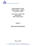
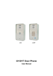
1
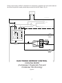
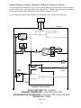
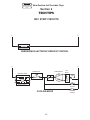
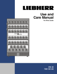
CONSUMER SERVICES TECHNICAL
EDUCATION GROUP PRESENTS
R-80
ENERGY EFFICIENT
TEMPERATURE REGULATING
and
DEFROST CONTROL SYSTEMS
Independent Temperature Control
for
Side-by-Side
Refrigerator/Freezers
Adaptive Defrost Control
for
Top-Mount and
Side-by-Side
Refrigerator/Freezers
I
JOB AID
Part No. 4321863
II
INTRODUCTION
This Job Aid, “Energy Efficient Temperature Regulating and Defrost Control Systems”, L-80, Part No.
4321863, provides specific information on the operation and servicing of energy efficient features
installed on Whirlpool-built refrigerator/freezers. These features are :
•
The “Smart Fan” or Independent Temperature Control (ITC) system is installed in some
freestanding SxS refrigerator/freezers beginning with the 1995 model year.
•
The solid state electronic Adaptive Defrost Control (ADC) system is installed in topmount and SxS refrigerator/freezers beginning with the 1992 model year.
“Energy Efficient Temperature Regulating and Defrost Control Systems” has been compiled to provide information on the most recent changes. Special attention has been given to:
•
•
•
Operational Theory
Testing Procedures
Servicing Procedures
GOALS AND OBJECTIVES
The goal of this Job Aid is to provide detailed information that will enable the service technician to
trouble shoot and service ADC and ITC systems.
The objectives of this Job Aid are:
The Service Technician will •
•
•
•
Have a working knowledge of the operational theory of ADC and ITC systems.
Understand the proper safety precautions.
Follow proper service procedures
Successfully return the refrigerator/freezer to proper operational status.
TO THE INSTRUCTOR/INDEPENDENT STUDENT
This Job Aid contains “Confirmation of Understanding Exercises” at the end of various sections. A
symbol that looks like this: ( . ) indicates that a pencil or pen will be necessary to complete the
exercise.
This Job Aid is designed to be used with the video tape, Energy EfficientTemperature Regulating and
Defrost Control Systems, Part No. 4321878. As you use this Job Aid you will see a symbol that looks
like this:
>>
It instructs you to view certain section of the video tape. the numbers of the sections you should view
appear in the lower left corner of the television screen.
WHIRLPOOL CORPORATION ASSUMES NO RESPONSIBILITY
FOR ANY REPAIRS MADE ON OUR PRODUCTS BY ANYONE
OTHER THAN AUTHORIZED SERVICE TECHNICIANS.
© 1995 Whirlpool Corporation, Benton Harbor, Michigan
III
TABLE OF CONTENTS
INTRODUCTION
III
TABLE OF CONTENTS
IV
Section 1 - SAFETY
1
Section 2 - ADAPTIVE DEFROST CONTROL
3
THEORY OF OPERATION
3
TESTING AND DIAGNOSIS
9
REPLACING THE ADC BOARD
10
Section 3 - INDEPENDENT TEMPERATURE CONTROL
13
THEORY OF OPERATION
13
TESTING AND DIAGNOSIS
24
REPLACING THE AIR BAFFLE ASSEMBLY AND THERMOSTATS
26
Section 4 - TECH TIPS
29
STRIP CIRCUITS
Adaptive Defrost Control
Independent Temperature Control
29
31
WARRANTY REPLACEMENT INFORMATION
33
IV
>>
View Section 1 of the video Tape
Section 1
SAFETY
! WARNING
s
ELECTRIC SHOCK HAZARD
A good electrical ground is required for this appliance.
Do not modify the three-prong plug on the power supply line cord. If it does not fit the
outlet, have a qualified electrician install the proper outlet.
Do not use an extension cord with these units.
Disconnect power before servicing.
Failure to follow these instructions may result in serious injury or death.
! WARNING
s
ELECTROSTATIC DISCHARGE (ESD) SENSITIVE ELECTRONICS
Do not open the package containing the service replacement electronic board until it
is time to install it. ESD conditions are present everywhere. ESD may damage or
weaken the electronic boards. The new board may appear to work well after repair
is finished, but failure may occur at a later date due to ESD stress.
Use an anti-static wrist strap.
Connect wrist strap to green ground connection point or unpainted metal in the
appliance.
-ORTouch your finger repeatedly to a green ground connection point
or unpainted metal in the appliance.
Before removing the board from its package, touch the anti-static bag
to a green ground connection point or unpainted metal in the appliance.
Avoid touching electronic parts or terminal contacts.
Handle electronic boards by its edges only.
1
2
>>
View Section 2 of the video Tape
Section 2
ADAPTIVE DEFROST CONTROL
THEORY OF OPERATION
General Information
Beginning in 1992, energy efficient and other selected models of refrigerator/freezers were equipped
with Adaptive Defrost Control (ADC). (Fig. 1)
Figure 1
The Adaptive Defrost Control is mounted in the same place in the control box as the standard electromechanical defrost timer. (Fig. 2) The ADC printed circuit board uses the same mounting screws
and holes. The 4 wire connector plug is also the same as that used with the standard timer. NOTE:
Units using standard mechanical timers cannot be retrofitted with ADC.
ADC
Figure 2
A brown and a white neutral wire are plugged into the other two terminals on the ADC.
The Adaptive Defrost Control has no serviceable components mounted on the microcomputer board.
If an ADC fails, the entire board should be replaced.
Operation
The general purpose of Adaptive Defrost Control is to limit the unit going into a defrost mode to only
those times when it is needed. This saves on the energy cost of operating the refrigerator/freezer.
The first time the unit is turned on the ADC will initiate a defrost mode after 6 hours of compressor
accumulated run-time. This defrost circuit will remain energized for a total of 21 or 25 minutes depending on model. The defrost heater will be energized until the bimetal opens.
3
After the initial defrost cycle is complete, the ADC will monitor Cumulative Compressor Run-Time and
the Duration of Previous Defrost Heater Time and adapt to time periods between 8 and 100 hours
between defrost modes.
If the defrost heater is energized for nearly all of the defrost cycle, the ADC will default to 8 hours
between defrost modes.
The ADC module is energized with 120VAC applied to connector pin 1. The circuit is closed through
connector pin 6 at all times. (Fig. 3) If this circuit should become de-energized for any reason the
module will not function and all memory in the microcomputer will be lost. If this should occur the
ADC will revert to 8 hours of cumulative run-time before initiating defrost.
115 VOLTS
60 HERTS
RIDGED WIRE
PK
BK
BI-METAL
BR
PK PK
TEST
TERM.
BR
BR
BR
W
DEFROST HEATER
PK BK OR
2
1
4
R BR W
3
5
6
C
NO
W
W
R/W
NC
EVAP. FAN
MOTOR
ELECTRONIC
DEFROST CONTROL
RT
ST A
OR
R
R
THERMOSTAT
S
S
BL RUN CAP.
W
C
C
W
OVERLOAD
RU
N
M
M
COMPRESSOR
PTC RELAY
R
W
COND. FAN
MOTOR
ELECTRONIC DEFROST CONTROL
ENERGIZING CONTROL CIRCUIT
Figure 3
4
During normal cooling 120VAC is directed to the compressor, evaporator fan motor and condenser
fan motor through the normally closed relay mounted on the ADC board. (Fig. 4)
115 VOLTS
60 HERTS
RIDGED WIRE
PK
BK
BI-METAL
BR
PK PK
TEST
TERM.
BR
BR
BR
W
DEFROST HEATER
PK BK OR
2
1
4
R BR W
3
5
6
C
NO
W
W
R/W
NC
EVAP. FAN
MOTOR
ELECTRONIC
DEFROST CONTROL
RT
ST A
OR
R
R
THERMOSTAT
S
S
BL RUN CAP.
W
C
C
W
OVERLOAD
RU
N
M
M
COMPRESSOR
PTC RELAY
R
W
COND. FAN
MOTOR
ELECTRONIC DEFROST CONTROL
COOLING MODE
(Compressor, Evaporator Fan and
Condenser Fan Running)
Figure 4
5
Defrost is initiated by an internal electronic clock in the ADC which will energize the relay directing
120VAC to the defrost heater. (Fig. 5)
115 VOLTS
60 HERTS
RIDGED WIRE
PK
BK
BI-METAL
BR
PK PK
TEST
TERM.
BR
BR
BR
W
DEFROST HEATER
PK BK OR
2
1
4
R BR W
3
5
6
C
NO
W
W
R/W
NC
EVAP. FAN
MOTOR
ELECTRONIC
DEFROST CONTROL
RT
ST A
OR
R
R
THERMOSTAT
S
S
BL RUN CAP.
W
C
C
W
OVERLOAD
RU
N
M
M
COMPRESSOR
PTC RELAY
R
W
COND. FAN
MOTOR
ELECTRONIC DEFROST CONTROL
COOLING MODE
(Monitoring Run-Time Circuit)
Figure 5
6
While the unit is in the cooling mode the ADC will monitor the cumulative compressor run-time through
connector pin 3. (Fig. 6)
115 VOLTS
60 HERTS
RIDGED WIRE
PK
BK
BI-METAL
BR
PK PK
TEST
TERM.
BR
BR
BR
W
DEFROST HEATER
PK BK OR
2
1
4
R BR W
3
5
6
C
NO
W
W
R/W
NC
EVAP. FAN
MOTOR
ELECTRONIC
DEFROST CONTROL
RT
ST A
OR
R
R
THERMOSTAT
S
S
BL RUN CAP.
W
C
C
W
OVERLOAD
RU
N
M
M
COMPRESSOR
PTC RELAY
R
W
COND. FAN
MOTOR
ELECTRONIC DEFROST CONTROL
DEFROST MODE
(Defrost Heater Energized)
Figure 6
7
While the unit is in the defrost mode the ADC will monitor the duration of the defrost heater run-time
through connector pin 5. (Fig. 7)
115 VOLTS
60 HERTS
RIDGED WIRE
PK
BK
BI-METAL
BR
PK PK
TEST
TERM.
BR
BR
BR
W
DEFROST HEATER
PK BK OR
2
1
4
R BR W
3
5
6
C
NO
W
W
R/W
NC
EVAP. FAN
MOTOR
ELECTRONIC
DEFROST CONTROL
RT
ST A
OR
R
R
THERMOSTAT
S
S
BL RUN CAP.
W
C
C
W
OVERLOAD
RU
N
M
M
COMPRESSOR
PTC RELAY
R
W
COND. FAN
MOTOR
ELECTRONIC DEFROST CONTROL
DEFROST MODE
(Monitoring Defrost Cycle Duration)
Figure 7
The microcomputer processes both the cumulative compressor run-time and the defrost heater runtime to determine when defrost mode is needed.
8
TESTING AND DIAGNOSIS
ADC Test Mode
The refrigerator/freezer defrost system can be checked by manually initiating a defrost cycle. There
are two methods of initiating the ADC Test Mode.
First Test Method:
1.
2.
3.
4.
5.
6.
7.
Turn
Turn
Turn
Turn
Turn
Turn
Turn
the thermostat off for 15 seconds.
the thermostat on for 5 seconds.
the thermostat off for 15 seconds.
the thermostat on for 5 seconds.
the thermostat off for 15 seconds.
the thermostat on for 5 seconds.
the thermostat off.
In 3 to 8 seconds the ADC should turn on the defrost heater (with the bimetal closed). NOTE: The
test mode will terminate when the bimetal opens.
If the refrigerator/freezer is already in defrost, Test Mode can be terminated by unplugging the refrigerator/freezer from the wall outlet and waiting 30 seconds before plugging it back in. The refrigerator/
freezer should immediately go into cooling mode if the thermostat is closed.
If this first test procedure fails to make the ADC initiate a defrost cycle, try the following procedure to
make the ADC begin the Test Mode.
Second Test Method:
1. Disconnect the refrigerator/freezer from the wall outlet for at least 30 seconds.
2. Turn the thermostat off.
3. Reconnect power to the refrigerator/freezer.
Within 3 to 8 seconds the ADC should turn on the defrost heater (with the bimetal close).
If the unit fails to go into the defrost mode during this test, the problem may not be with the ADC. A
defective bimetal may be the cause of the failure. The ADC will only go into a test mode if the bimetal
is closed. If the ADC senses an open bimetal it will return to the cooling mode within 3 to 8 seconds.
HELPFUL HINT: Upon entering the Test Mode, the relay mounted on the ADC board should turn off
the compressor and turn on the defrost heater. Listen for the relay to click.
•
If the relay clicks one time when entering the Test Mode, check for continuity in the defrost heater.
•
If the relay clicks two times, check for an open bimetal.
Defrost Circuit Tests
Inspect all connectors to verify that they are seated properly and are not corroded.
Bimetal Test
1. Disconnect the unit from the wall outlet.
2. Locate the loose brown and pink test lead harness plug in the control box.
9
3. Use a VOM set to the Rx1 (resistance) scale and check for continuity between the brown
and pink leads.
a. If the evaporator is cold, the bimetal should be closed and the
meter will show 0 ohms or continuity.
b. If the evaporator is warm, the bimetal will be open and the meter
will indicate infinite resistance or no continuity.
4. Visually inspect the bimetal to determine whether it is opening before frost or ice is cleared
from the evaporator. The evaporator cover will have to be removed for this.
Defrost Heater Test
1. Disconnect the unit from the wall outlet.
2. Locate the loose brown and pink test lead harness plug in the control box.
3. Check for proper heater resistance between the brown test lead and any white common
lead in the control box. The resistance reading should be within normal tolerances of the
range noted in the Tech Sheet supplied with the unit. If not, the heater should be replaced.
4. If the defrost heater tests good in the previous test, verify that the heater is not
grounded by checking continuity between each of the wire leads to the heater itself.
a. Disconnect the heater wire connectors from the heater located behind the
evaporator cover.
b. Place one test lead from the VOM on one wire connector of the heater.
Place the other test lead on the external body of the heater element. Any
continuity or resistance indicates the heater is grounded and should be replaced.
NOTE: Only after all other components in the defrost system have been tested or inspected should
the ADC microcomputer board be replaced.
REPLACING THE ADC BOARD
! NOTICE
s
DISCONNECT POWER BEFORE SERVICING
FAILURE TO DO SO MAY RESULT IN SERIOUS INJURY OR DEATH
HANDLE THE PRINTED CIRCUIT BOARD BY ITS EDGES
AVOID TOUCHING ELECTRICAL CONNECTIONS OR TERMINAL CONTACTS
10
Replacement Parts Compatibility
The ADC Service Replacement Assembly, Part No. 4386981 is supplied with a plug adapter kit to
replace the following ADC board installed in Whirlpool-built refrigerator/freezers (Fig. 8):
2154985
Figure 8
The ADC Universal Service Replacement Assembly, Part No. 483187 will directly replace the following ADC boards:
2162373
2169266
2162270
2169268
The ADC Universal Service Replacement Assembly, Part No. 483187 will require modification to
replace the following ADC boards:
2169269
2154958
2169267
Instructions
1. Remove the Control Box from the refrigerator section of the unit.
2. Remove the two connector plugs from the ADC board.
3. Remove the ADC board from the Control Box.
4. When replacing original part numbers 2154958, 2169267 or 2169269, remove the resistor
marked R17 from the circuit by cutting the wire leads to the resistor in two places with wire
cutters. (Fig. 9)
Figure 9
5. Replace the new board in the Control Box.
6. Replace the Control Box in the refrigerator.
11
Section 2
(.) CONFIRMATION OF LEARNING EXERCISE
1. The purpose of Adaptive Defrost Control is:
o
o
o
o
a)
b)
c)
d)
To extend the life of the defrost heater element.
To bypass the bimetal.
To limit a refrigerator/freezer going into defrost to only those times when it is needed.
None of the above.
2. The ADC module performs 2 basic functions:
o
o
o
o
a)
b)
c)
d)
Monitoring
Monitoring
Monitoring
Monitoring
compressor run-time and defrost heater run-time.
the temperature of the freezer and refrigerator sections.
compressor run-time and refrigerator/freezer temperatures.
defrost heater run-time and refrigerator section temperature.
3. If a refrigerator/freezer does not go into defrost:
o
o
o
o
a)
b)
c)
d)
Replace the ADC module immediately.
Check to be sure all connectors are seated properly and are not corroded.
Call Technical Assistance for instructions.
Change out the bimetal and defrost heater element.
4. The ADC Universal Service Replacement Assembly will replace:
o a) All ADC modules currently installed in refrigerator/freezers.
o b) Will need some modification to replace some ADC modules currently installed in refrigerator/ freezers.
o c) Should not be used without calling Technical Assistance.
o d) a and b.
5. The ADC module is located:
o
o
o
o
a)
b)
c)
d)
In the unit compartment.
In the freezer section behind the evaporator cover.
In the control box.
None of the above.
6. If the unit does not go into a test mode (using either Test Method 1 or 2):
o
o
o
o
a)
b)
c)
d)
Check the defrost heater element for shorting.
Check for a closed bimetal.
Check thermostat resistance.
Check evaporator fan motor.
7. (OPTIONAL) If a refrigerator/freezer equipped with ADC is available:
a) Perform a resistance check on the bimetal and defrost heater element.
b) Replace the ADC module.
12
>>
View Section 3 of the video Tape
Section 3
INDEPENDENT TEMPERATURE CONTROL
THEORY OF OPERATION
General Information
Beginning with the 1995 model year some free standing
SxS refrigerator/freezers have been equipped with the
“Smart Fan” or Independent Temperature Control (ITC)
system which allows for separate temperature control in
both the refrigerator and freezer compartments through
the use of two thermostats and a motorized air baffle
between the two sections of the appliance. (Fig. 10)
Figure 10
Both thermostats are located in the control box in the refrigerator section. (Fig. 11) The freezer
temperature sensing tube is routed to and located inside the freezer section behind the air duct to
sense freezer temperature. The refrigerator temperature sensing tube is located around the diffuser
discharge to sense refrigerator temperature.
Operation
Figure 11
HELPFUL HINTS: The auxillary switch directly controls the following functions.
•
•
•
Freezer Thermostat
Refrigerator Thermostat
All Cooling Function Components
The freezer thermostat directly controls:
•
•
•
Compressor
Condenser Fan
Evaporator Fan (Only when the air baffle is closed.)
The refrigerator thermostat directly controls:
•
•
Motorized Air Baffle
Evaporator Fan (Only when the air baffle is open.)
During the defrost cycle the compressor, condenser fan, evaporator fan and the motorized air baffle
motor are de-energized. The air baffle remains in the position it was in (either open or closed) when
the defrost cycle started.
13
Freezer and Refrigerator Satisfied
If both the freezer and refrigerator are “satisfied” the freezer thermostat is open and the refrigerator
thermostat is at the cold or “satisfied” position. No voltage is available to the compressor, condenser
fan motor or evaporator fan motor. There is no voltage available to the air baffle motor and it remains
closed. (Fig. 12)
115 VOLTS
60 HERTS
RIDGED WIRE
PK
BI-METAL
BK
BK
PK
OR
R
BR
PK PK
TEST
TERM.
BR
OR
BR
W
DEFROST HEATER
TIMER
FREEZER
TERM.
AUX.
OFF
3
2
OR
1
RT
STA
R
R
BL
S
W
C
C
OR/BK
RUN CAP.
S
W
OVERLOAD
RU
N
M
M
COMPRESSOR
PTC RELAY
R
W
R
COND. FAN
MOTOR
1
S3
W
2
EVAP. FAN
MOTOR
REFRIG.
THERM.
S2
COLDER
3
1
BK/Y
W
6
2
OR/
BK
3
COLD
AIR BAFFLE
MOTOR
4
Y/R
NOT
USED
S1
5
AIR BAFFLE ASSEMBLY
AIR BAFFLE CLOSED
AUXILLARY SWITCH - CLOSED
FREEZER THERMOSTAT - SATISFIED
REFRIGERATOR THERMOSTAT - SATISFIED (COLD)
AIR BAFFLE - CLOSED
Figure 12
14
Freezer Calling for Cooling - Refrigerator Satisfied
If the freezer thermostat closes, calling for cooling, 120VAC is directly applied to the compressor and
condenser fan motor. Voltage is also applied to the evaporator fan motor through switch S3 (1 - 2) of
the Air Baffle Assembly. Since the refrigerator is satisfied, its thermostat remains in the cold position
and the air baffle remains closed. (Fig. 13) This configuration allows the freezer only to be cooled.
115 VOLTS
60 HERTS
RIDGED WIRE
PK
BI-METAL
BK
BK
PK
OR
R
BR
PK PK
TEST
TERM.
BR
OR
BR
W
DEFROST HEATER
TIMER
FREEZER
TERM.
AUX.
OFF
3
2
OR
1
RT
STA
R
R
BL
S
W
C
C
OR/BK
RUN CAP.
S
W
OVERLOAD
RU
N
M
M
COMPRESSOR
PTC RELAY
R
W
R
COND. FAN
MOTOR
1
S3
W
2
EVAP. FAN
MOTOR
REFRIG.
THERM.
S2
COLDER
3
1
BK/Y
W
6
2
OR/
BK
3
COLD
4
Y/R
NOT
USED
S1
AIR BAFFLE
MOTOR
5
AIR BAFFLE ASSEMBLY
AIR BAFFLE CLOSED
AUXILLARY SWITCH - CLOSED
FREEZER THERMOSTAT - CALLING FOR COOL
REFRIGERATOR THERMOSTAT - SATISFIED (COLD)
AIR BAFFLE - CLOSED
Figure 13
15
Freezer Satisfied - Refrigerator Calling For Cooling
If the freezer is satisfied (freezer thermostat open) and the refrigerator thermostat calls for cooling,
120VAC will be applied through switch S2 ( 3 - 6) energizing the air baffle motor to begin openingthe
baffle. (Fig. 14)
115 VOLTS
60 HERTS
RIDGED WIRE
PK
BI-METAL
BK
BK
PK
OR
R
BR
PK PK
TEST
TERM.
BR
OR
BR
W
DEFROST HEATER
TIMER
FREEZER
TERM.
AUX.
OFF
3
2
OR
1
RT
STA
R
R
S
BL
S
W
C
C
OR/BK
RUN CAP.
W
OVERLOAD
RU
N
M
M
COMPRESSOR
PTC RELAY
R
W
R
COND. FAN
MOTOR
1
S3
W
2
EVAP. FAN
MOTOR
REFRIG.
THERM.
S2
COLDER
3
1
BK/Y
OR/
BK
W
6
2
3
COLD
AIR BAFFLE
MOTOR
4
Y/R
NOT
USED
S1
5
AIR BAFFLE ASSEMBLY
AIR BAFFLE OPENIG
AT STARTUP
AUXILLARY SWITCH - CLOSED
FREEZER THERMOSTAT - SATISFIED
REFRIGERATOR THERMOSTAT - JUST CALLING FOR COOL (COLDER)
AIR BAFFLE - OPENING UP
Figure 14
16
Freezer Satisfied - Refrigerator Calling For Cooling (continued)
Once the air baffle has reached its full open position switch S2 opens and switch S1 closes deenergizing the air door motor, leaving the door in the open position. Voltage is now applied to the
evaporator fan motor through switch S3 (3 - 2) of the air baffle assembly. (Fig. 15)
115 VOLTS
60 HERTS
RIDGED WIRE
PK
BI-METAL
BK
BK
PK
OR
R
BR
PK PK
TEST
TERM.
BR
OR
BR
W
DEFROST HEATER
TIMER
FREEZER
TERM.
AUX.
OFF
3
2
OR
1
R
S TA
R
R
T
BL RUN CAP.
S
S
W
C
C
OR/BK
W
OVERLOAD
RU
N
M
M
COMPRESSOR
PTC RELAY
R
W
R
COND. FAN
MOTOR
1
S3
W
2
EVAP. FAN
MOTOR
REFRIG.
THERM.
S2
COLDER
3
1
BK/Y
OR/
BK
W
6
2
3
COLD
4
Y/R
NOT
USED
S1
AIR BAFFLE
MOTOR
5
AIR BAFFLE ASSEMBLY
AIR BAFFLE OPEN
AUXILLARY SWITCH - CLOSED
FREEZER THERMOSTAT - SATISFIED
REFRIGERATOR THERMOSTAT - CALLING FOR COOL (COLDER)
AIR BAFFLE - OPEN
Figure 15
17
Freezer Satisfied - Refrigerator Just Satisfied
The evaporator fan motor will continue to run until the refrigerator thermostat is satisfied (moves to
the “COLD” position. This turns the evaporator fan motor off and applies voltage to the air baffle door
motor through switch S1. The baffle will then close. (Fig. 16)
115 VOLTS
60 HERTS
RIDGED WIRE
PK
BI-METAL
BK
BK
PK
OR
R
BR
PK PK
TEST
TERM.
BR
OR
BR
W
DEFROST HEATER
TIMER
FREEZER
TERM.
AUX.
OFF
3
2
OR
1
R
S TA
R
R
T
BL RUN CAP.
S
S
W
C
C
OR/BK
W
OVERLOAD
RU
N
M
M
COMPRESSOR
PTC RELAY
R
W
R
COND. FAN
MOTOR
1
S3
W
2
EVAP. FAN
MOTOR
REFRIG.
THERM.
S2
COLDER
3
1
BK/Y
OR/
BK
W
6
2
3
COLD
AIR BAFFLE
MOTOR
4
Y/R
NOT
USED
S1
5
AIR BAFFLE ASSEMBLY
AIR BAFFLE CLOSED
AUXILLARY SWITCH - CLOSED
FREEZER THERMOSTAT - SATISFIED
REFRIGERATOR THERMOSTAT - JUST SATISFIED (COLD)
AIR BAFFLE - STARTING TO CLOSE
Figure 16
18
Freezer Satisfied - Refrigerator Satisfied
Once the aire baffle has reached its full closed position, switch S1 opens, switch S2 closes
and switch S3 changes position (1 - 2). (Fig. 17) This configuration allows the refrigerator
section only to be cooled.
115 VOLTS
60 HERTS
RIDGED WIRE
PK
BI-METAL
BK
BK
PK
OR
R
BR
PK PK
TEST
TERM.
BR
OR
BR
W
DEFROST HEATER
TIMER
FREEZER
TERM.
AUX.
OFF
3
2
OR
1
RT
STA
R
R
S
BL
S
W
C
C
OR/BK
RUN CAP.
W
OVERLOAD
RU
N
M
M
COMPRESSOR
PTC RELAY
R
W
R
COND. FAN
MOTOR
1
S3
W
2
EVAP. FAN
MOTOR
REFRIG.
THERM.
S2
COLDER
3
1
BK/Y
OR/
BK
W
6
2
3
COLD
4
Y/R
NOT
USED
S1
AIR BAFFLE
MOTOR
5
AIR BAFFLE ASSEMBLY
AIR BAFFLE CLOSED
AUXILLARY SWITCH - CLOSED
FREEZER THERMOSTAT - SATISFIED
REFRIGERATOR THERMOSTAT - SATISFIED (COLD)
AIR BAFFLE - CLOSED
Figure 17
19
Freezer Calling for Cooling - Refrigerator Calling for Cooling
If both the freezer thermostat closes (calling for cooling) and the refrigerator thermostat moves to the
colder position (calling for cooling), 120VAC is directly applied to the compressor and condenser fan
motor. Voltage is also applied to switch S3 (1 to 2) to energize the evaporator fan motor while the air
baffle door is opening. This begins the cooling process for the freezer. Voltage is applied through
switch S2 (4 to 6) to energize the air baffle motor and open the air baffle. (Fig. 18)
115 VOLTS
60 HERTS
RIDGED WIRE
PK
BI-METAL
BK
BK
PK
OR
R
BR
PK PK
TEST
TERM.
BR
OR
BR
W
DEFROST HEATER
TIMER
FREEZER
TERM.
AUX.
OFF
3
2
OR
1
RT
STA
R
R
BL
S
W
C
C
OR/BK
RUN CAP.
S
W
OVERLOAD
RU
N
M
M
COMPRESSOR
PTC RELAY
R
W
R
COND. FAN
MOTOR
1
S3
W
2
EVAP. FAN
MOTOR
REFRIG.
THERM.
S2
COLDER
3
1
BK/Y
W
6
2
OR/
BK
3
COLD
AIR BAFFLE
MOTOR
4
Y/R
NOT
USED
S1
5
AIR BAFFLE ASSEMBLY
AIR BAFFLE CLOSED
AT STARTUP
AUXILLARY WITCH - CLOSED
FREEZER THERMOSTAT - CALLING FOR COOL
REFRIGERATOR THERMOSTAT - JUST CALLING FOR COOL (COLDER)
AIR BAFFLE - OPENING UP
Figure 18
20
Freezer Calling for Cooling - Refrigerator Calling for Cooling (continued)
Once the baffle has reached its full open position switch S2 opens and switch S1 closes de-energizing the air door motor, leaving the baffle in the open position. Voltage is now applied to the evaporator fan motor through switch S3 (3 to 2) of the air baffle assembly. (Fig. 19)
This configuration allows both the freezer and refrigerator to be cooled at the same time.
115 VOLTS
60 HERTS
RIDGED WIRE
PK
BI-METAL
BK
BK
PK
OR
R
BR
PK PK
TEST
TERM.
BR
OR
BR
W
DEFROST HEATER
TIMER
FREEZER
TERM.
AUX.
OFF
3
2
OR
1
RT
STA
R
R
BL
S
W
C
C
OR/BK
RUN CAP.
S
W
OVERLOAD
RU
N
M
M
COMPRESSOR
PTC RELAY
R
W
R
COND. FAN
MOTOR
1
S3
W
2
EVAP. FAN
MOTOR
REFRIG.
THERM.
S2
COLDER
3
1
BK/Y
W
6
2
OR/
BK
3
COLD
4
Y/R
NOT
USED
S1
AIR BAFFLE
MOTOR
5
AIR BAFFLE ASSEMBLY
AIR BAFFLE ALREADY OPEN
AUXILLARY SWITCH - CLOSED
FREEZER THERMOSTAT - CALLING FOR COOL
REFRIGERATOR THERMOSTAT - CALLING FOR COOL (COLDER)
AIR BAFFLE - OPEN
Figure 19
21
Freezer Calling for Cooling - Refrigerator Satisfied
When the refrigerator section thermostat moves to the cold position (satisfied), 120VAC is applied
through switch S1 (4 to 6) which closes the air baffle. (Fig. 20)
115 VOLTS
60 HERTS
RIDGED WIRE
PK
BI-METAL
BK
BK
PK
OR
R
BR
PK PK
TEST
TERM.
BR
OR
BR
W
DEFROST HEATER
TIMER
FREEZER
TERM.
AUX.
OFF
3
2
OR
1
RT
STA
R
R
BL
S
W
C
C
OR/BK
RUN CAP.
S
W
OVERLOAD
RU
N
M
M
COMPRESSOR
PTC RELAY
R
W
R
COND. FAN
MOTOR
1
S3
W
2
EVAP. FAN
MOTOR
REFRIG.
THERM.
S2
COLDER
3
1
BK/Y
W
6
2
OR/
BK
3
COLD
AIR BAFFLE
MOTOR
4
Y/R
NOT
USED
S1
5
AIR BAFFLE ASSEMBLY
AIR BAFFLE STARTING
TO CLOSE
AUXILLARY SWITCH - CLOSED
FREEZER THERMOSTAT - CALLING FOR COOL
REFRIGERATOR THERMOSTAT - JUST SATISFIED (COLD)
AIR BAFFLE - STARTING TO CLOSE
Figure 20
22
Freezer Calling for Cooling - Refrigerator Satisfied (continued)
Once the baffle has reached its full closed position, switch S1 opens, S2 closes and S3 changes
position. The evaporator fan motor is now energized through switch S3 (1 to 2). (Fig. 21)
115 VOLTS
60 HERTS
RIDGED WIRE
PK
BI-METAL
BK
BK
PK
OR
R
BR
PK PK
TEST
TERM.
BR
OR
BR
W
DEFROST HEATER
TIMER
FREEZER
TERM.
AUX.
OFF
3
2
OR
1
R
ST A
R
R
T
BL
S
W
C
C
OR/BK
RUN CAP.
S
W
OVERLOAD
RU
N
M
M
COMPRESSOR
PTC RELAY
R
W
R
COND. FAN
MOTOR
1
S3
W
2
EVAP. FAN
MOTOR
REFRIG.
THERM.
S2
COLDER
3
1
BK/Y
W
6
2
OR/
BK
3
COLD
AIR BAFFLE
MOTOR
4
Y/R
NOT
USED
S1
5
AIR BAFFLE ASSEMBLY
AIR BAFFLE CLOSED
AUXILLARY SWITCH - CLOSED
FREEZER THERMOSTAT - ON AND CALLING FOR COOL
REFRIGERATOR THERMOSTAT - ON AND SATISFIED (COLD)
AIR BAFFLE - CLOSED
Figure 21
23
TESTING AND DIAGNOSIS
ITC TEST MODE
The Air Baffle Module functions can be checked in the following manner:
1. Verify that the product is not in defrost.
2. Open the refrigerator and freezer doors and allow the unit to warm up enough totrip the refrigerator and freezer thermostats. When both the freezer and refrigerator thermostats call for
cooling, the baffle door should open.
3. Note the thermostat settings and remove the control box front cover.
4. Set the controls in the following manner. Check for the given results:
Settings:
a. Move the freezer thermostat control to the far right
b. Move the refrigerator thermostat control the the far left.
Results:
Air Baffle - In 15 seconds the baffle should be fully closed.
Compressor - ON
Condenser Fan - ON
Evaporator Fan - ON
Settings:
a. Freezer Thermostat Control to the far right
b. Refrigerator Thermostat Control to the far right
Results:
Air Baffle - In 15 seconds the baffle should be fully open.
Evaporator Fan - ON
Compressor - ON
Condenser Fan - ON
If the given results do not occur, check all electrical components. Evaluate all wiring connections, the
freezer thermostat, the refrigerator thermostat, the defrost timer, the evaporator fan, the condenser
fan and the compressor. If these components all check out good, the following procedure will allow a
complete evaluation of the component inside the Air Baffle Module.
24
Motorized Air Baffle Assembly Test: (Make sure to notice the position of the air baffle door OPEN or CLOSED)
Air Baffle OPEN:
Continuity between terminals 3 & 2 (checks S3)
No continuity between terminals 1 & 2 (checks S3)
Approximately 8,200 ohms resistance between terminals 4 & 6.
(This varifies continuity through S1 and resistance through the Air Door Motor)
No continuity between terminals 3 & 6 (checks S2)
Air Baffle CLOSED:
Continuity between terminals 1 & 2 (checks S3)
No continuity between terminals 3 & 2 (checks S3)
Approximately 8,200 ohms resistance between terminals 3 & 6.
(This varifies continuity through S2 and resistance through the Air Door Motor)
No continuity between terminals 4 & 6 (checks S2)
NOTE: Do not attempt to repair the Module. Replace the entire baffle assembly.
Thermostat Test
Auxillary Switch:
NOTE: The auxillary switch is found inside the freezer thermostat housing. It operates independently of the freezer thermostat.
In ON position:
Continuity between terminals 3 & 2
In Off position:
No continuity between terminals 3 & 2.
Freezer Thermostat:
In CLOSED position (Calling for Cooling):
Continuity between terminals 2 & 1
In OPEN position (Satisfied):
No continuity between terminals 2 & 1.
Refrigerator Thermostat:
In COLDER position (Calling for Cooling):
Continuity between terminals 2 & 1
No continuity between terminals 2 & 3
In COLD position (Satisfied):
Continuity between terminals 2 & 3
No continuity between terminals 2 & 1
25
REPLACING THE BAFFLE MODULE
NOTE: When replacing the Air Baffle Assembly, note the routing and location of the freezer and
refrigerator temperature sensing tubes. Be sure to replace the tubes in their same locations or the
refrigerator/freezer will not operate properly.
! WARNING
s
DISCONNECT POWER BEFORE SERVICING
FAILURE TO DO SO MAY RESULT IN SRIOUS INJURY OR DEATH
Ü
1. Remove the screw securing the conduit
cover over the wiring harness from the top
left edge of the refrigerator section. (Fig. 22)
CONDUIT
COVER
Ü
Instructions:
BAFFLE
COVER
2. Remove the screw securing the plastic
covering over the Baffle Module. (Fig. 23)
Figure 22
(Refrigerator Compartment)
LIGHT
LENS
Ü
AIR
SCOOP
ASSEMBLY
Ü
4. Remove the light lens and air scoop assembly
from the back of the freezer section. (Fig. 23)
Ü
3. Disconnect the two harness plugs from the
Baffle Module.
FREEZER
SENSING
TUBE
Figure 23
(Freezer Compartment)
5. Carefully guide the freezer compartment temperature sensing tube from its position as
the Baffle Assembly is pulled from the compartment wall in the refrigerator section.
6. Carefully unwrap the refrigerator compartment temperature sensing tube from air
defuser.
7. Unsnap the baffle assembly from the air duct.
8. the Baffle Assembly is not serviceable and must be replaced as a unit. To reinstall, reverse
the instructions above.
26
REPLACING THE THERMOSTATS AND
TEMPERATURE SENSING TUBES
The temperature sensing tubes are an integral part of the freezer and refrigerator thermostat controls
located in the control box in the refrigerator compartment. (Fig. 24)
Figure 24
Instructions
1. The Air Baffle Asembly must be removed from its position in the compartment wall as described above.
2. Remove the control box eschtcheon.
3. Remove the two to four screws securing the control box to the top of the refrigerator
compartment.
4. Disconnect the two wiring harness plugs from their connector blocks and remove the ground
wire clip.
5. The control box and air baffle assembly can now be removed from the
refrigerator for service.
a. The freezer thermostat contains the auxillary switch, the thermostat control and the freezer
temperature sensing tube and is replaced as one unit.
b. The refrigerator thermostat contains the thermostat control and
refrigerator temperature sensing tube and is replaced as one unit.
NOTE: When replacing the the control box and air baffle assembly, note the routing and location of
the freezer and refrigerator temperature sensing tubes. Be sure to replace the tubes in their proper
locations or the refrigerator/freezer will not operate properly.
27
Section 3
(.) CONFIRMATION OF LEARNING EXERCISE
1. The purpose of Independent Temperature Control is to:
o
o
o
o
a)
b)
c)
d)
Keep the freezer compartment colder than the refrigerator compartment.
Allow for separate temperature control in the freezer and refrigerator compartments.
Reduce compressor run-time.
Reduce the amount of refrigerant required in the sealed system.
2. The refrigerator thermostat controls:
o
o
o
o
a)
b)
c)
d)
The
The
The
The
evaporator fan motor and the air baffle motor.
evaporator fan motor and the condenser fan motor.
compressor and the air baffle motor.
compressor and the evaporator fan motor.
3. If the air baffle assembly does not function properly:
o
o
o
o
a)
b)
c)
d)
Replace the air baffle assembly immediately.
Check the defrost heater element.
Check all electrical connections and components before replacing the air baffle assembly.
Call Technical Assistance for instructions.
4. Replacing the air baffle assembly requires:
o
o
o
o
a)
b)
c)
d)
Disassembly in both the freezer and refrigerator compartments.
Special tools
Removal of the evaporator cover.
None of the above.
5. Replacing the thermostats and sensing tubes requires:
o
o
o
o
a)
b)
c)
d)
Disassembly in both the freezer and compartments.
Removing the evaporator cover.
Replacing the air baffle assembly.
None of the above.
6. The freezer thermostat controls:
o
o
o
o
a)
b)
c)
d)
Compressor and condenser fan motor only.
Compressor, condenser fan motor and evaporator fan motor (when baffle is open.)
Compressor, condenser fan motor and evaporator fan motor (when baffle is closed.)
Air baffle motor and condenser fan motor.
7. The evaporator fan motor:
o
o
o
o
o
a)
b)
c)
d)
e)
Is controlled by the freezer thermostat only.
Is controlled by the refrigerator thermostat only.
Is controlled by a switch in the air baffle assembly.
Is controlled by both the refrigerator and freezer thermostats.
c and d
6. (OPTIONAL) If a unit with ITC is available:
a) Replace the Air Baffle Assembly.
b) Replace the freezer and refrigerator thermostats and sensing tubes.
28
>>
View Section 4 of the video Tape
Section 4
TECH TIPS
ADC STRIP CIRCUITS
L1
N
1
6
ELECTRONIC
DEFROST CONTROL
ENERGIZING ELECTRONIC DEFROST CONTROL
L1
N
THERMOSTAT
COMPRESSOR
DEFROST TIMER
RT
STA
s
1
4
2
5
S
s
s
NO
NC
ELECTRONIC
DEFROST CONTROL
OVERLOAD
RUN
CAP.
s
C
6
PTC
RELAY
RUN
M
3
COND. FAN
MOTOR
COOLING MODE
29
EVAP. FAN
MOTOR
ADC STRIP CIRCUITS (con't.)
N
L1
THERMOSTAT
s
DEFROST TIMER
1
4
s
6
s
2
NO
NC
5
ELECTRONIC
DEFROST CONTROL
3
MONITORING COMPRESSOR RUN-TIME
L1
N
DEFROST TIMER
1
4
s
6
s
2
NO
NC
ELECTRONIC
DEFROST CONTROL
5
DEFROST
HEATER
BI-METAL
3
DEFROST MODE
L1
N
DEFROST TIMER
1
4
s
6
s
2
NO
NC
ELECTRONIC
DEFROST CONTROL
5
BI-METAL
3
MONITORING DEFROST HEATER RUN-TIME
30
ITC STRIP CIRCUITS
L1
N
FREEZER
THERMOSTAT
s
AUXILLARY
SWITCH
2
3
2
1
1
S3
3
s
1
3
2
2
AIR DOOR
S2 MOTOR
4
S1
REFRIGERATOR
THERMOSTAT
6
AIR BAFFLE ASSEMBLY
AUXILLARY SWITCH - CLOSED
FREEZER THERMOSTAT - SATISFIED
REFRIGERATOR THERMOSTAT - JUST CALLING FOR COOLING
AIR BAFFLE - OPENING
L1
FREEZER
THERMOSTAT
s
AUXILLARY
SWITCH
2
3
2
1
1
S3
3
s
2
1
3
2
AIR DOOR
S2 MOTOR
4
S1
REFRIGERATOR
THERMOSTAT
6
AIR BAFFLE ASSEMBLY
AUXILLARY SWITCH - CLOSED
FREEZER THERMOSTAT - SATISFIED
REFRIGERATOR THERMOSTAT - JUST SATISFIED (COLD)
AIR BAFFLE - CLOSING
31
ITC STRIP CIRCUITS (con't.)
L1
N
FREEZER
THERMOSTAT
s
AUXILLARY
SWITCH
2
3
2
1
1
S3
3
s
1
4
3
2
2
EVAP. FAN
MOTOR
AIR DOOR
S2 MOTOR
6
S1
REFRIGERATOR
THERMOSTAT
AIR BAFFLE ASSEMBLY
AUXILLARY SWITCH - CLOSED
FREEZER THERMOSTAT - SATISFIED
REFRIGERATOR THERMOSTAT - CALLING FOR COOL (COLDER)
AIR BAFFLE - OPEN
N
L1
FREEZER
THERMOSTAT
AUXILLARY
SWITCH
COMPRESSOR
s
RT
STA
2
S
2
1
RUN
CAP.
s
C
3
PTC
RELAY
RUN
M
COND. FAN
MOTOR
1
S3
3
2
AIR DOOR
S2 MOTOR
4
S1
6
AIR BAFFLE ASSEMBLY
AUXILLARY SWITCH - CLOSED
FREEZER THERMOSTAT - CALLING FOR COOL
REFRIGERATOR THERMOSTAT - SATISFIED (COLD)
AIR BAFFLE - CLOSED
32
EVAP. FAN
MOTOR
L1
L2
FREEZER
THERMOSTAT
AUXILLARY
SWITCH
COMPRESSOR
s
RT
STA
2
S
2
1
RUN
CAP.
s
C
3
PTC
RELAY
RUN
M
COND. FAN
MOTOR
1
S3
3
s
2
2
AIR DOOR
S2 MOTOR
1
4
3
S1
REFRIGERATOR
THERMOSTAT
EVAP. FAN
MOTOR
6
AIR BAFFLE ASSEMBLY
AUXILLARY SWITCH - CLOSED
FREEZER THERMOSTAT - CALLING FOR COOL
REFRIGERATOR THERMOSTAT - CALLING FOR COOL (COLDER)
AIR BAFFLE - OPEN
PRODUCT SPECIFICATIONS
AND
WARRANTY INFORMATION SOURCES
FOR PRODUCT SPECIFICATIONS AND WARRANTY INFORMATION CALL:
FOR KITCHENAID PRODUCTS: 1-800-422-1230
FOR WHIRLPOOL PRODUCTS: 1-800-253-1301
FOR TECHNICAL ASSISTANCE WHILE AT THE CUSTOMER'S HOME CALL:
THE TECHNICAL ASSISTANCE LINE: 1-800-253-2870
Have your store number ready to identify you as an Authorized Servicer
33
ANSWER SHEET
CONFIRMATION OF LEARNING EXERCISES
34
35
36